Language selection

Search

Patent 2169712 Summary

Third-party information liability

Some of the information on this Web page has been provided by external sources. The Government of Canada is not responsible for the accuracy, reliability or currency of the information supplied by external sources. Users wishing to rely upon this information should consult directly with the source of the information. Content provided by external sources is not subject to official languages, privacy and accessibility requirements.

Claims and Abstract availability

Any discrepancies in the text and image of the Claims and Abstract are due to differing posting times. Text of the Claims and Abstract are posted:

  • At the time the application is open to public inspection;
  • At the time of issue of the patent (grant).
(12) Patent: (11) CA 2169712
(54) English Title: ANNEALING BASE FOR HOOD-TYPE ANNEALING FURNACES
(54) French Title: BASE DE RECUIT POUR FOUR DE RECUIT A HOTTE
Status: Expired and beyond the Period of Reversal
Bibliographic Data
(51) International Patent Classification (IPC):
  • C21D 9/00 (2006.01)
  • C21D 9/673 (2006.01)
(72) Inventors :
  • EBNER, PETER HELMUT (Austria)
  • LOCHNER, HERIBERT (Austria)
(73) Owners :
  • PETER HELMUT EBNER
  • HERIBERT LOCHNER
(71) Applicants :
(74) Agent: SMART & BIGGAR LP
(74) Associate agent:
(45) Issued: 2001-07-17
(22) Filed Date: 1996-02-16
(41) Open to Public Inspection: 1996-08-25
Examination requested: 1997-05-30
Availability of licence: N/A
Dedicated to the Public: N/A
(25) Language of filing: English

Patent Cooperation Treaty (PCT): No

(30) Application Priority Data:
Application No. Country/Territory Date
A337/95 (Austria) 1995-02-24

Abstracts

English Abstract

An annealing base for hood-type annealing furnaces com- prises a support (6) receiving the annealing goods, in par- ticular stacked sheet metal coils. The support (6) rests on the distributor (4) of a central fan (5). The vertical fan axis is surrounded by a thermally insulating filling member (3). The load of the distributor (4) is transmitted by means of a supporting structure (9, 10) through the filling member (3) to a frame member (2) supported on the founda- tion (1). The filling member (3) consists of insulating wool or the like gas-tightly encapsulated in sheet metal. To avoid the formation of cracks in the filling member (3) during the annealing process, a stronger shaped ring (9) adapted to the bottom surface of the distributor (4) is in- serted in the sheet metal constituting the capsule of the filling member (3), which shaped ring constitutes the sup- porting structure by means of two concentric sheet metal cylinders (10) connecting the same with the frame member (2).


French Abstract

Une base de recuit pour four de recuit à hotte comprend un support (6) recevant les matériaux de recuit, en particulier des rouleaux de tôles empilées. Le support (6) repose sur le distributeur (4) d'un ventilateur central (5). L'axe de ventilateur vertical est entouré par un élément de remplissage thermiquement isolant (3). La charge du distributeur (4) est transmise au moyen d'une structure de support (9, 10) par le biais de l'élément de remplissage (3) vers un élément de cadre (2) supporté sur une base (1). L'élément de remplissage (3) est composé de laine isolante ou une matière semblable renfermée de manière étanche au gaz dans une tôle. Pour éviter la formation de fissures dans l'élément de remplissage (3) lors du processus de recuit, un anneau mis en forme plus résistant (9) adapté à la surface inférieure du distributeur (4) est inséré dans la tôle constituant la capsule de l'élément de remplissage (3), anneau mis en forme qui constitue la structure de support au moyen de deux cylindres de tôles concentriques (10) reliant celle-ci à l'élément de cadre (2).

Claims

Note: Claims are shown in the official language in which they were submitted.

5
CLAIMS:
1. An annealing base for hood-type annealing furnaces
comprising a support receiving the annealing goods, in
particular stacked wire coils, on a distributor of a central
fan, a thermally insulting filling member arranged between the
distributor and a frame member and disposed thereunder and
surrounding a vertical fan axis, and comprising a supporting
structure transmitting the load from the distributor through
the filling member to said frame member supported on the
foundation, where the filling member consists of insulating
wool gas-tightly encapsulated in sheet metal, characterized in
that in the sheet metal constituting the capsule of the filling
member directly below the distributor a shaped ring adapted to
a bottom surface of said distributor and conforming in shape to
the bottom surface of said distributor and of greater thickness
than the sheet metal is inserted, which shaped ring constitutes
the supporting structure by means of two concentric sheet metal
cylinders connecting the same with the frame member.
2. The annealing base as claimed in claim 1,
characterized in that the lower edge of the sheet metal
cylinders has recesses and is welded with the frame member only
between said recesses.

Description

Note: Descriptions are shown in the official language in which they were submitted.


2 i 6't-~ 1 2
Kommerzialrat
Dipl.-Ing. Peter Helmut Ebner
Leonding (Austria)
Dipl.-Ing. Heribert Lochner
Leonding (Austria)
Annealing Base for Hood-Type Annealing Furnaces
This invention relates to an annealing base for hood-type
annealing furnaces comprising a support receiving the an-
nealing goods, in particular stacked sheet metal coils, on
the distributor of a central fan, a thermally insulating
filling member disposed thereunder and surrounding the fan
axis, and comprising a supporting structure transmitting
the load from the distributor through the filling member to
a frame member lying on the foundation, where the filling
member consists of insulating wool or the like gas-tightly
encapsulated in sheet metal.
When the annealing goods have been placed on the support, a
protective hood reaching up to the frame member is placed
over the annealing goods and the base, which protective
hood contains a protective gas circulated by the fan, which
chiefly serves to avoid oxidations on the surface of the
annealing goods. The protective hood is then covered by a
heating hood, whose heating means, in general gas or oil
burners or electric heating elements, heats the protective
hood on the outside, which protective hood in turn heats
the protective gas and as a further conse~uence the an-
nealing goods. Upon completion of the heat treatment the
heating hood is replaced by a cooling hood, and the charge
is cooled.

2 1 6~ / 1 2
_ -- 2
The supporting structure of the annealing base, which ser-
ves to dissipate the load of the weight of the annealing
goods to the foundation, has so far chiefly consisted of
individual, mostly tubular supports welded to the envelop-
ing sheet metal, which supports have supporting elements in
their upper portion, which absorb the changes in length oc-
curring during heating or cooling between the upper en-
veloping sheet metal and the lower frame member by means of
a sliding friction or bending stress acting on the sup-
ports, where relatively large dilatations or contractions
occur, as the temperature difference between the distribu-
tor and the frame member is several hundred degrees. In the
case of an improper construction or workmanship, cracks in
the sheet metal capsule can already occur after a short
operating time, so that an undesired mixing of the protec-
tive gas with the gas definitely present in the filling
member, i.e. air or nitrogen, can occur. Such defects are
chiefly due to the fact that a relative movement at the
sliding surfaces is impaired, so that transverse forces are
developed in the supports, which may cause welding cracks.
It is therefore the object of the invention to eliminate
this deficiency and create an annealing base of the above-
described type, where no cracks occur in the capsule con-
stituting the filling member.
This object is solved by the invention in that in the sheet
metal constituting the capsule of the filling member di-
rectly below the distributor a shaped ring adapted to the
bottom surface of said distributor and of substantially
greater thickness than the sheet metal is inserted, which
constitutes the supporting structure by means of two con-
centric sheet metal cylinders connecting it with the frame
member.

216'~il2
-- 3
The two concentric sheet metal cylinders, which are mostly
firmly welded with the shaped ring on the side of the an-
nealing chamber, are subjected from the top to the same
temperature as said shaped ring, so that all members are
dilating uniformly, and there can be no differences in
length or sliding movements between the individual members.
When the sheet metal cylinder and the shaped ring are heat-
ed, they are increased in diameter by the coefficients of
thermal expansion corresponding to the respective materi-
als, and then shrink again when they are cooled, without a
risk of producing welding cracks or the like. Since the in-
sulating wool or the like contained in the filling member
is elastic, there is not produced an opening between the
metal parts and the insulation material during said proces-
ses, which opening would provide for a transport of heat
from the top into the lower base portion toward the founda-
tion as a result of natural gas flows.
In a further embodiment of the invention the lower edge of
the sheet metal cylinder comprises recesses and is welded
with the frame member only between said recesses. As a re-
sult, the conduction of heat inside the sheet metal ring
from the top to the frame member is reduced considerably,
as the recesses prevent such thermal conduction.
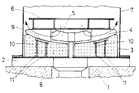
In the drawing, the subject-matter of the invention is il-
lustrated by way of example, wherein:
Fig. 1 represents a vertical section of an annealing base,
and
Fig. 2 is a graphical representation of a part of a sheet
metal cylinder.
On the foundation 1 a frame member 2 is supported, which in
turn carries filling members 3. On the filling members 3
the distributor 4 of a central fan 5 is supported, with the

21~12
distributor in turn carrying a support 6 for the annealing
goods, in general sheet metal coils. Over the entire an-
nealing base an annealing hood 7 is placed.
For transmitting the load of the annealing goods from the
support 6 to the foundation 1 there is first of all pro-
vided the distributor 4. In the filling member 3, which
consists of a gas-tight sheet metal capsule and is filled
with insulating wool 8, a supporting structure is disposed
for transmitting the load to the frame member 2.
This supporting structure consists of a relatively strong
shaped ring 9 adapted to the bottom surface of the distri-
butor ~ and inserted in the sheet metal of the filling mem-
ber 3, which shaped ring is connected with the frame member
2 by two concentric sheet metal cylinders 10, which are
welded both with the frame member 2 and with the shaped
ring 9. From Fig. 2 it can be seen that the sheet metal
rings 10 have recesses 11 at their lower edge and can
therefore be welded with the frame member only between said
recesses 11.

Representative Drawing
A single figure which represents the drawing illustrating the invention.
Administrative Status

2024-08-01:As part of the Next Generation Patents (NGP) transition, the Canadian Patents Database (CPD) now contains a more detailed Event History, which replicates the Event Log of our new back-office solution.

Please note that "Inactive:" events refers to events no longer in use in our new back-office solution.

For a clearer understanding of the status of the application/patent presented on this page, the site Disclaimer , as well as the definitions for Patent , Event History , Maintenance Fee  and Payment History  should be consulted.

Event History

Description Date
Time Limit for Reversal Expired 2015-02-16
Letter Sent 2014-02-17
Inactive: IPC from MCD 2006-03-12
Inactive: Entity size changed 2002-02-06
Grant by Issuance 2001-07-17
Inactive: Cover page published 2001-07-16
Pre-grant 2001-04-03
Inactive: Final fee received 2001-04-03
Notice of Allowance is Issued 2000-10-13
Letter Sent 2000-10-13
Inactive: Approved for allowance (AFA) 2000-09-28
Amendment Received - Voluntary Amendment 2000-03-22
Amendment Received - Voluntary Amendment 1999-06-24
Inactive: S.30(2) Rules - Examiner requisition 1999-02-25
Inactive: Application prosecuted on TS as of Log entry date 1997-06-12
Letter Sent 1997-06-12
Inactive: Status info is complete as of Log entry date 1997-06-12
Request for Examination Requirements Determined Compliant 1997-05-30
All Requirements for Examination Determined Compliant 1997-05-30
Application Published (Open to Public Inspection) 1996-08-25

Abandonment History

There is no abandonment history.

Maintenance Fee

The last payment was received on 2001-01-24

Note : If the full payment has not been received on or before the date indicated, a further fee may be required which may be one of the following

  • the reinstatement fee;
  • the late payment fee; or
  • additional fee to reverse deemed expiry.

Please refer to the CIPO Patent Fees web page to see all current fee amounts.

Owners on Record

Note: Records showing the ownership history in alphabetical order.

Current Owners on Record
PETER HELMUT EBNER
HERIBERT LOCHNER
Past Owners on Record
None
Past Owners that do not appear in the "Owners on Record" listing will appear in other documentation within the application.
Documents

To view selected files, please enter reCAPTCHA code :


To view images, click a link in the Document Description column. To download the documents, select one or more checkboxes in the first column and then click the "Download Selected in PDF format (Zip Archive)" or the "Download Selected as Single PDF" button.

List of published and non-published patent-specific documents on the CPD .

If you have any difficulty accessing content, you can call the Client Service Centre at 1-866-997-1936 or send them an e-mail at CIPO Client Service Centre.


Document
Description 
Date
(yyyy-mm-dd) 
Number of pages   Size of Image (KB) 
Cover Page 2001-07-09 1 50
Claims 2000-03-22 1 36
Cover Page 1996-06-03 1 17
Description 1996-06-03 4 149
Abstract 1996-06-03 1 30
Claims 1996-06-03 1 35
Drawings 1996-06-03 1 23
Representative drawing 2001-07-09 1 17
Claims 1999-06-24 1 38
Representative drawing 1998-04-29 1 19
Acknowledgement of Request for Examination 1997-06-12 1 187
Reminder of maintenance fee due 1997-10-19 1 111
Commissioner's Notice - Application Found Allowable 2000-10-13 1 163
Maintenance Fee Notice 2014-03-31 1 170
Fees 2003-01-28 1 38
Correspondence 2001-04-03 2 58
Fees 2002-01-23 1 38
Fees 2012-01-19 1 65