Note: Descriptions are shown in the official language in which they were submitted.
CA 02170010 2000-11-30
LIFT TRUCK WITH INERTIAL DAMPENER
BACKGROUND
This invention relates to material handling apparatus, and more particularly,
to
improved arrangements for inertially damping the motion of the unpowered,
suspended
rear wheel commonly used on narrow-aisle lift trucks. One class of narrow-
aisle lift
trucks employs a pair of unpowered non-steerable front wheels, or load wheels,
a steerable
powered drive wheel assembly rigidly mounted near one rear corner of the
truck, and an
unpowered vertically-sprung idler wheel assembly near the other rear corner of
the truck.
With all four wheels mounted on the same base frame, one wheel must be
vertically
sprung, or otherwise floor irregularities could result in loss of traction bye
the drive :wheel.
In some applications the vertically-sprung idler wheel assembly uses a
castered idler wheel
which is self steering. One early form of truck of that type is shown in U.S.
Patent No.
2,564,002. In various other applications the sprung idler wheel is not
cantered, but instead
steered via a linkage. A truck of this latter type is shown in U.S. Patent No.
3,392,797.
The suspended wheel is suspended from the frame of the truck by coil springs,
a
torsion bar of leaf springs as shown and described in U.S. Patent No.
4,813,512,
assigned to the assignee of this patent. Lift trucks achieve
significant economies when vehicle frames of a uniform type are used with
either a
2 0 castered idler wheel or a linkage-steered idler wheel. Provision of an
idler wheel
mounting arrangement which will readily accommodate either type of steering is
disclosed
in U.S. Patent No. 3,392,797. In the idler wheel mounting arrangements
disclosed in that
patent, the pivot steering axis of the idler wheel is located somewhat
inwardly from a
lateral extremity of the truck to allow space for a castered wheel to swing.
The springs
2 5 used to oppose weight on the idler wheel must be aligned with the pivot or
steering axis,
so that they do not impose moments which would cause undue bearing wear, and
hence
the springs also must be located undesirably inwardly from the lateral
extremity of the
truck, where they tend to interfere with provisions of an unobstructed
operator
compartment and waste space.
3 0 One problem with prior art lift trucks is that they tilt when the truck
stops abruptly
or abruptly changes direction or both. While such motion will not tip the
truck, it is
disconcerting to an operator. Normally an operator will slow down and allow
the tilt to
naturally dissipate before resuming travel. Accordingly, such unwanted tilting
reduces the
efficiency of the operator and the overall productivity of lift truck
operations.
21~~Q1
2 -
A principal object of the present invention is to provide a suspended idler
wheel
mounting arrangement wherein the suspension means has its motion dampened in
order to
limit the tilt of a lift truck following an abrupt stop or an abrupt change in
direction.
BRIEF DESCRIPTION OF THE DRAWINGS
Figure 1 is a rear elevation view of one form of lift truck incorporating a
preferred
form of the invention, with certain parts cut away and certain parts omitted
for sake of
clarity.
Figure 2 is a downward-section viewtaken at lines 2-2 in Figure 1.
Figure 3 is an elevation view of a lift truck with its mast extended and
supporting a
load.
Figure 4 is a partial perspective and partial cut away view of a lift truck
showing
an inertial damper on the suspended wheel.
Figure 5 is an elevation view of the damper mounted between two coil springs.
Figure 6 is an end view of the damper of FIG 5.
Figures 7a, 7b, and 7c are top, side and end views, respectively, of a
wheel-mounting member used to install a linkage-steered idler wheel.
Figures 8a and 8b are top and side views, respectively, of a wheel-mounting
member used to install a self steered castered idler wheel.
2 o Figure 9 is a view taken at lines 9-9 in Figure 2, with certain parts
omitted for
sake of clarity.
Figure l0A and lOB are top and elevation views of a second embodiment.
Figure 11A and 11B are top and elevation views of a third embodiment.
Figure 12 is a rear elevation of another, type of lift truck suspension that
will
2 5 benefit from this invention.
DETAILED DESCRIPTION
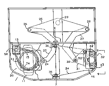
_ Figures 1 and 2 illustrate a truck 100 with a steering linkage shown
connected to
steer the suspended idler wheel. The left side of the rear of the truck is
shown supported
3 0 by a steerable powered drive wheel assembly 20 which is rotatably mounted
on plate 21
(Figure 1) rigidly affixed relative to the base frame 116 of the truck 100.
The drive wheel
assembly includes an electric traction motor TM which drives drive wheel 11
through
CA 02170010 2000-11-30
- 3 -
reduction gearing 12. A rotary hydraulic steering motor SM is fixedly mounted
relative to
the base frame 116 of the truck 100 and is operated by a conventional operator
control
(not shown) in which an operator-controlled steering wheel positions a
follower valve,
causing rotation of steering motor SM in the direction of, and in an amount
proportional
to, steering wheel rotation. The shaft of motor SM carries a sprocket 13 which
is
connected via chain 14 (Figure 2) to a sprocket member 1 S formed on drive
unit 20.
Chain 14 is omitted from Figure 1 for sake of clarity.
Drive wheel assembly 20 may comprise, for example, a powered steerable wheel
unit of the nature shown in U.S. Patent-No: - 3,392.,7-97; with a sprocket.15
or .gear.added
to such a unit to allow it to be rotated. One end of a rigid link 23 is
pivotally attached to
drive unit 20 via spherical bearing 24. The other end of link 23 is pivotally
attached to
one end of a bell crank or rocker member 25 via spherical bearing 26. A center
portion of
bell crank 25 is pivotally attached to the base frame 116 of the truck 100 via
needle roller
bearing 29. As powered drive wheel assembly 20 is rotated counterclockwise (as
viewed
in Figure 2) from the position shown, it will be appreciated that link 23 will
rotate bell
crank 25 clockwise about bearing 29. One end of a link 27 is pivotally
attached to bell
crank 25 by spherical bearing 28, and the other end of link 27 is pivotally
attached by
spherical bearing 30 to an arm 31 affixed to a non-castered idler wheel
assembly 32. As
bell crank 25 rotates clockwise, idler wheel assembly 32 is rotated counter
clockwise. The
2 0 described steering linkage arrangement is not apart o the present
invention, but instead,
further described and claimed in U.S. Patent No. 4,754,837. It is to be
understood that
the idler wheel mounting arrangement of the present invention does not require
such a
steering linkage arrangement, nor indeed any linkage to steer the idler wheel.
The idler wheel assembly 32 is shown journalled by means of a roller thrust
bearing 40 (Figure 1) near the outer end of a rigid A-frame arm, or lever
member 34,
which is shown pivotally mounted on the base frame 116 of the truck 100, near
the lateral
center of the truck 100, by tnuznion bearings 35, 36, so that A-frame lever
member 34
may rotate limited amounts about a horizontal longitudinally-extending axis x-
x (Figure 2).
3 0 A pair of compression springs 42, 43 are shown interposed between the
outer end of the
A-frame lever member and a plate affixed to the base frame 116 of the truck
100. Hence
springs 42, 43 compress in accordance with the vertical weight imposed on the
idler
:''":_
2170010
- 4 -
wheel, and as the truck 100 travels over irregular floor surfaces the idler
wheel may move
upwardly and downwardly relative to the frame 116 of the truck 100 to insure
that
adequate weight to provide traction is always imposed on the powered drive
wheel 11 of
drive unit 20. As shown in Figure 3, when truck 100 stops abruptly or abruptly
changes
direction, the springs 42, 43 are compressed and oscillate, thereby causing
the mast 110 to
tilt oscillate in the direction of arrow 103. Such oscillation is enhanced by
a load 114
carried on fork 112 that are extended to the top of the mast 110.
As floor surface irregularities cause the A-frame lever member 34 to rotate
about
axis x-x, the steering axis of the idler wheel assembly -departs . slightly
from-the vertical; --- -. -- ------
and because the idler wheel steering shaft is journalled in lever member 34
for rotation
about a fixed axis, the slight rotation of lever member causes floor cbntact
of the idler
wheel to vary between the inside and outside edges of the idler wheel tire.
Constant
running on the inside or outside edge of the idler wheel tire could cause
unacceptable
wear. However, because A-frame lever member 34 is long, i.e., pivoted a
substantial
lateral distance from the idler wheel tire, and because the pivot axis x-x of
the A-frame
lever member is very near the floor, the angular amount by which the idler
wheel steering
axis departs from the vertical is modest, and because appreciable rotation of
lever member
34 occurs only when floor irregularities are encountered, the described
arrangement results
in acceptably little tire wear.
2 0 Idler wheel assembly 32 includes an idler wheel 16 (shown -partially
cutaway in
Figure 1), and a vertical pivot or steering shaft 52 (Figure 2). When the
idler wheel
assembly 32 is to be steered via a linkage, as shown in Figures 1 and 2, for
example, that
assembly utilizes a non-cantered wheel mounting member 50 of the nature shown
in
Figures 7a-7c. Alternatively, when the idler wheel is to be self steering, a
wheel mounting
2 5 member 60 of the type shown in Figures 8a and 8b is used in place of
member 50.
As seen in.Figures 7a, 7b, and 7c, a.wheel mounting member 50 for mounting a
linkage-steered idler wheel comprises an upper plate member Sl carrying an
upstanding
pivot shaft 52, a pair of depending side plates, 53, 54, and an attachment arm
plate 31 to
which link 27 (Figure 1) is pivotally connected at hole 31a. Upper plate
rr~e~fiber .51
3 0 carries an annular groove S la in which a thrust bearing fits. A pair of
holes 55, 56 in side
plates 53, 54. accommodate the axle (not shown) of a conventional idler wheel,
so that the
<. ._ v
2170010
- 5 -
axis of such an axle lies directly below the idler wheel steering axis (i.e.,
the axis of shaft
52), as shown in Figure 7b.
As shown in Figures 8a and 8b, the wheel mounting member 60 used for mounting
a self steering caster wheel is formed quite similarly with an upper plate
member 61
carrying an upstanding steering shaft 62, and a pair of depending side plates
63, 64, but
with arm 31 omitted because no link need be connected. Also, the idler wheel
axle holes
65, 66 are offset (by dimension d, Figure 8b) from the steering axis of shaft
62 to provide
a desired amount of cantering. From the above it will be seen that the same
basic truck
100 can be readily equipped for either- linkage- steering or caster steering
of the sprung_ --_ . .- _- - . . _
1 o idler wheel, by mere selection of which form of wheel mounting member (50
or 60) is
used for the idler wheel, and if the cantered form of idler wheel is used.
links 23 and 27
and crank 25, and their associated bearings are not installed.
A nut 49 is screwed onto the threaded upper portion of shaft 52 or shaft 62.
As
best seen in Figure 9, adjustment of springs 42 and 43 is accomplished by
rotation of bolts
45, 46. Bolts 45, 46 each have a hexagonal portion which may be readily
grasped with a
wrench, an upper portion which seats in a respective bore in plate 44, and a
lower portion
threaded into a respective spring retainer 47, 48, which seats in the top of
one of the
springs. Damper 150 is disposed between springs 42, 43 with one end of damper
150
coupled to the base frame 116 of truck 100 and the other end of the damper 150
coupled
2 0 to the A-frame 34.
Turning to Figures 5 and 6, there is shown one embodiment of the inertial
damper
150. An interior slider plate 170 is disposed between outer plates 160, 180.
Outer plate
160 has a pair of friction pads 161, 169 mounted on its interface and abutting
one face of
a slider plate 170. In a similar manner, outer plate 180 has a pair of
friction pads 181,
2 5 189 mounted on its interface and facing the other face of slider plate
170. As shown in
Figure 5, the upper friction pad 161 of outer plate 160 and the lower friction
pad 169 are
held on the outer plate 160 with a plurality of rivets 165. A similar riveting
arrangement
is_used to fix the friction pads 181, 189 to outer plate 180. Slider plate ~
70 has an
elliptical opening 172 to allow for vertical motion. Outer plate 160 has
anwaperring 166
3 0 that is generally aligned with the elliptical opening 172 of the slider
plate 170. Outer plate
180 has a corresponding opening 186, not shown. A pair of belville washers
162, 182 are
respectively disposed against the outer faces of the slider plates 160, 180.
The belville
- 6 -
X170410
washers are held in place by respective retainers 163, 183. An adjusting bolt
164 engages
the retainers 163, 183 and can be turned to adjust the pressure exerted by the
belville
washers 162, 182 on the outer plates 160, 180.
The outer plate 160 has a bent portion 190 that fits in a suitable slot 184 of
the
other outer plate 180. The outer plate 180 has_ a sleeve 153 with an opening
154. The
opening 154 and the sleeve fit between mounting lugs 142, 144. Mounting lugs
142, 144
and sleeve 154 have a common bore. A suitable pin is secured in the bore in
order to
couple the outer plates 160, 180 to the frame 34 of the suspended wheel 16
In operation, as the truck-100 moves backward and.abruptly stops the mast -110
.- - .. _-.. _
1 o begins to tilt in the direction indicated by arrow 103 pivots about a line
between the drive
wheel contact with the floor and the right front load wheel contact with the
floor so that
the base 116 of the truck 100 compresses the springs 42, 43. Without the
inertial damper
150 the truck 100 would oscillate aided by springs 42, 43. The truck would
continue to
oscillate in this manner until the oscillation is dissipated in friction
inherent in the
suspension members. This friction is neither sufficient nor predictable enough
to
effectively control truck sway or oscillation for operator comfort. However,
with the
inertial damper 150, the slider plate 170 which is coupled to the frame 44 has
its motion
frictionally retarded by the friction pads 161, 169, 18.1, and 189 that bear
upon the slider
plate 170.
2 0 As mentioned above, the amount of damping is adjustable by the amount of
tension
imposed upon the belville washers 162, I82. That tension is adjustable by
adjusting nut
164. Those skilled in the art will appreciate that other biasing members than
belville
washers may be used to adjust the pressure of the friction pads on the slider
plate 170.
Accordingly, in the alternative embodiments 200 and 201 shown in
Figures 10A, lOB, 11A and 11B, the belville
washers are replaced with a compression spring 210. Multiple springs can also
be used.
The spring 210 is disposed between a compression plate 211 and outer plate
160. A pair
of bolts 212, 214 engage threaded holes in plate 180. By turning the bolts
212, 214, the
compression plate 211 can be moved toward outer plate 160 to increase
frictional force on
3 0 slider 170 or can be moved in the opposite direction to reduce friction
force ~n fhe slider
plate 170. The length of the compression spring and consequently its force may
be
suitably adjusted by turning the bolts 212 and 214.
2170010
Lift trucks with different suspension types can be aided by this invention. An
common example of an other suspension is shown in Figure 12. In that example,
the
drive wheel unit 310 and idler wheel 312 are rigidly but rotafebly attached to
a common
connecting beam 314 running laterally across the truck. The connecting beam is
pivotally
mounted to the truck chassis by a pivot pin or bolt 316 near the truck center
line. The
pivot pin or bolt 316 is oriented in a horizontal direction parallel to the
truck's fore-aft
axis. With this arrangement, either wheel may rise or fall while following
floor contours
and keep all four of the truck's wheels on the floor. If the idler wheel, for
instance,
dropped into a depression, the connecting beam would pivot relative to the
truck chassis
with the drive end of the truck dropping approximately one half of the drop of
the idler
wheel. Alternatively, the same action would occur if the drive wheel dropped
into a
depression. The lateral position of the connecting beam pivot pin or bolt 310
relative to
the distance between the drive and idler wheels will determine the relative
loading on each
wheel. Moving the pin 316 closer.to the drive wheel will increase the drive
wheel loading
for increased traction. Conversely, moving the pin closer to the drive tire
will decrease
the loading on the drive tire for increased drive tire life. Either a steered
idler wheel or
caster wheel may be used with this arrangement as noted in the earlier case.
The truck 300 is also prone to sway in a manner described earlier. Instead of
pivoting on the drive tire 311- and dipping down on the idler wheel 312 due to
spring
2 0 compression as in the earlier version, the truck 300 would pivot instead
on the pivot pin in
a similar manner. By applying on inertial damper 150 or 200 between the
connecting
beam 314 and the truck frame 308 as shown in Figure 12 truck sway or
oscillation can be
limited.
Having thus described the preferred embodiment. of the invention, those
skilled in
2 5 the art will appreciate that further modifications,. additions, and
changes thereto may be
made in the preferred embodiments of the invention without departing from the
spirit and
scope-of the following claims: