Note: Descriptions are shown in the official language in which they were submitted.
2~00~
WO96/01041 ~ PCT~L95/00231
A CONSTRUCTION INCLUDING AN IMPLEMENT FOR AUTOMATICALLY
MILKING ANIMALS
The present invention relates to a construction
including an implement for automatically milking Anim~ls,
such as cows, having one or more milking boxes and one or
more milking robots for automatically coupling teat cups to
the teats of the animals. So as to prevent that an animal
present in a milking box is troubled during milking by the
milking equipment and to achieve that the animal can move
about more freely in the milking box, the construction is
characterized according to the invention, in that during
milking a milk tube connected to a teat cup is freely movable
in such a manner that the teat cup can follow the animal's
movements with a slight resistance. The milk tube is then
preferably of such a design that during milking it is movable
with a slight resistance along or at a slight height above
the floor of a milking box. The invention, therefore, also
relates to a construction including an implement for
automatically milking animals, such as cows, having one or
more milking boxes and one or more milking robots for
automatically coupling teat cups to the teats of the ~nim~l s,
the construction then being characterized in that a milk tube
connected to a teat cup is of such a design that during
milking it is movable with a slight resistance along or at a
slight height above the floor of a milking box. More in
particular, a milk tube can extend during milking freely
movably under a robot arm which is part of the milking robot.
t If the milk tube is not secured to the robot arm, the tube
will be capable of moving more freely. During milking the
WO96/01041 ~ d J~ ; PCT~g5/00231
milk tube can extend in a mainly horizontal plane and be
movable in this plane. In this situation, the milk tube may
in many cases be, seen in a plan view, in the shape of a
loop, more specifically in the shape of a U. More in par-
ticular, a milk tube can extend, during milking, from the
teat cup to which the milk tube is connected, taken in a plan
view, obliquely forwardly in the direction of walk of the
animal and outwardly and from there may extend in the shape
of a loop. The invention, therefore, also relates to a
construction including an implement for automatically milking
~ni~l S~ such as cows, having one or more milking boxes and
one or more milking robots for automatically coupling teat
cups to the teats of the animals, the construction then being
characterized in that, during milking, a milk tube extends
from the teat cup to which the milk tube is connected, taken
in a plan view, obliquely forwardly in the direction of walk
of the animal and outwardly and from there extends in the
shape of a loop. The milk tubes connected to the several teat
cups can extend from the teat cups at both sides of a milking
box to as far as aside of the milking box. More in par-
ticular, a milk tube may extend in the shape of a loop to a
point of connection of a milk line, disposed at the side of a
milking box.
In accordance with a further feature of the inven-
tion, the construction is characterized in that a milking
robot includes at least one omnilaterally movable robot arm,
which acts as a carrier for one of the teat cups, whilst the
robot arm, after a teat cup has been fitted to a teat of an
animal, can be moved to outside the reach of an animal
present in a relevant milking box. The teat cups remain in
connection with the respective robot arms by means of a
flexible connecting element, such as a cord. When a teat cup
is to be uncoupled, then the relevant robot arm is moved
towards the teat on which the teat cup has been fitted,
whilst simultaneously or shortly thereafter the teat cup is
pulled up against the robot arm and the robot arm is
thereafter moved, at least mainly, to outside the milking
box. In a preferred embodiment, each robot arm acts as a
carrier for only one teat cup, so that consequently four of
WO96/01041 ~1 7 0 0 4 S PCT~n~5/00231
these robot arms are present in the milking robot. On the
other hand, a robot arm may also act as a carrier for two
teat cups, in which case two robot arms are present in the
milking robot; these robot arms can then be disposed, for
example, on both sides of the relevant milking box. Expressed
in a more general way, a~ milking robot can include at least
two robot arms, which are movable independently of each other
and act as a carrier for one or more teat cups, which robot
arms are arranged on both sides of or near a milking box and
wherein, in a specific embodiment, the robot arms are
provided with adjusting means disposed one above the other,
which, in a spatial view, results in an advantageous
disposition. The adjusting means may include a four-bar
linkage, with the aid of which a robot arm is movable in the
upward direction. In addition, the adjusting means may
include a further four-bar linkage, with the aid of which a
teat cup is movable from the side of a milking box to under
the udder of an animal standing therein. This further four-
bar linkage is preferably connected to the said first four-
bar linkage in such a manner that it is rotating around a
mainly vertical shaft. The two four-bar linkages and the
pivotability about the said vertical shaft, provides an
omnidirectional motional capability of the robot arm and
consequently also of the teat cup or teat cups connected
thereto. A robot arm may accommodate an adjusting cylinder,
more in particular a pneumatic cylinder, with the aid of
which, through the intermediary of the aforesaid flexible
element, a teat cup can be pulled up against the robot arm
and optionally can be maintained in that position.
To determine the position of the teats of the
animal, a detector, more in particular a laser detector, will
be present, which detector will preferably be disposed on a
separate robot arm construction. Thereby the detector can
always be moved to such a position under the animal that the
teats, whatever their position and how closely they may be
located relative to each other, can always be detected. The
detection of the position of the teats can be further
facilitated if the detector can be moved from a rest position
at or near the side of a milking box to a first and a second
WO96/010~1 2 1~ ~ ~ 4 5 PCT~95/00231
working position, whilst in one of these working positions
the position of a teat of an animal standing in the milking
box can be determined. More in particular, it is possible in
the first working position to determine the positions of two
teats, e.g. the front pair and in the second working position
the positions of the other two teats, e.g. the rear pair.
When no animal is being milked, then the teat cups
will be in the rest position at or near a side or at or near
the sides of a milking box. In an advantageous embodiment in
accordance with the invention, the teat cups are automatical-
ly cleaned precisely in this rest position. For that purpose,
spray heads connected to a washing circuit may have been
disposed at or near both sides of a milking box, to which the
teat cups are connectable independently of each other. When
four robot arms are used, each of which acts as a carrier of
one teat cup, and when these robot arms are arranged two by
two on either side of a milking box, then the spray heads
will have been disposed two by two at or near both sides of
the milking box. These specific locations are such that in
their rest position, in which they are pulled up against a
corresponding robot arm, the teat cups are in connection with
the spray heads.
The invention further relates to a method of
milking animals, such as cows, in a milking box and with the
aid of a milking robot having teat cups which are
automatically couplable to the teats of an animal, and
wherein, when the teat cups are in the coupled state, the
robot arm or robot arms of the milking robot are moved
predominantly to outside the milking box, whilst the teat
cups remain in connection with the robot arm or robot arms
with the aid of a flexible element, such as a cord, and
wherein, when a teat cup is to be uncoupled from a teat, the
robot arm or a respective robot arm moves up to the teat cup.
Simultaneously with or shortly after this motion, the teat
cup which is to be uncoupled can be pulled up against the
robot arm. In this method, it is preferred that the teat cups
are uncoupable from the teats one after the other.
For a better understanding of the invention and to
show how the same may be carried into effect, reference will
WO96/01041 PCT~n95/00231
`21700~
now be made, by way of example, to the accompanying drawings,
in which:
Figure 1 is a side view of a milking box of the
invention;
Figure 2 is a rear view of a milking robot, a teat
cup being connected to a teat of an animal standing in the
milking box;
Figure 3 is a rear view of the milking robot,
wherein the teat cups are connected to the teats of an animal
present in the milking box and wherein the robot arm is
thereafter retracted to outside the milking box;
Figure 4 is a plan view of the milking box with the
milking robot, wherein the teat cups have all four been
connected to the teats of an animal standing in the milking
box and wherein the robot arms have thereafter been retracted
to outside the milking box;
Figure 5 is a side view of a milking box accom-
modating a cow, of which the front and rear teats are at
unequal heights, and in which figure a detector is shown in
the position in which it can determine the location of the
rear teats, and
Figure 6 is a plan view of the milking box shown in
Figure 5 cont~; n; ng the detector, and the manner in which
this detector is movable and cleanable.
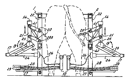
Figure 1 shows, in a side view, a milking box 1 in
which a cow to be milked is present. The milking box 1
includes a railing 2 which limits the milking box at all four
sides, an entrance door 3 at the rear side and two exit doors
4 and 5 having been arranged in this railing at the two
longitudinal sides (see Figure 4). Via one of these exit
doors the animal can be conducted from the milking box to a
shed area or a pasture, whilst via the other door the animal
can be conducted to a special isolation area, e.g. because
mastitis has been detected during milking. The entrance and
exit doors are under the control of a computer system, not
further shown. At the leading side of the milking box l a
feeding trough 6 has been disposed, which is part of an
automatic feeding system. The animals to be milked wear a
collar 7, which is equipped with a transponder 8 which
WO96/01041 ~ 17 ~ PCT ~ 95/00231
cooperates with a sensor 9 disposed at or near the feeding
trough 6. When an animal enters the milking box l and has
advanced that far that it can put its head into the feeding
trough 6, the distance between the transponder 8 and the
sensor 9 is such that communication between the two elements~
8 and 9 occurs. The transponder 8 and the sensor 9, which is
connected to the computer system, constitute an animal iden-
tification system. As soon as communication between the
transponder 8 and the sensor 9 becomes possible, the ~n;m~l
is identified, which has for its result that a file stored
for this animal in the memory of the computer system becomes
accessible, which file includes various data, such as data
for the automatic supply of food, the automatic connection of
the teat cups and the subsequent automatic milking operation
and for monitoring the heath condition of this ~n;mAl
After the animal has entered the milking box l and
has been identified therein, a detector lO, here in the form
of a laser detector, is moved to under the animal. In the
Figures l and 4, the detector lO is disposed on a robot arm
system ll, formed by robot arms 15 and 16 which are pivotal
about round vertical shafts 12 and 13, this robot arm system
ll being attached to the railing 2 in such a manner that it
is pivotal about the shaft 13. The robot arms 15 and 16 are
pivotal with the aid of computer-controlled motors 37 and 38,
for which stepping motors are preferably employed. Using the
detector lO, the position of the teats relative to the
milking box l can be determined, whereafter teat cups 18 can
be fitted on the teats. The detector lO and the means for
fitting the teat cups 18 to the teats together form a milking
robot. In the embodiment shown, these means include a
separate robot arm construction 9 for each of the teat cups
18. Such a robot arm construction l9 includes a first four-
bar linkage 20, with the aid of which a vertical carrier 21
is connected capable of moving in the upward direction to
frame portions 22 of the railing 2. The pivotal shafts, by
means of which this four-bar linkage is connected to the
frame portions, are denoted by 20A. At the lower side of the
carrier 21 there is present a second four-bar linkage 23,
with the aid of which a robot arm 24 is movable from outside
~ 217004~
WO96/01041 PCT~ns5/00231
the milking box 1 into the milking box to under an animal
present therein and can again be retracted to outside the
milking box. This robot arm 24 is furthermore pivotal about a
vertical shaft 25 relative to the carrier 21. Each of the
robot arms 24 acts as a carrier for one or the teat cups 18.
By means of the first and second four-bar linkages 20 and 23,
t respectively, and the pivotal construction about the shaft
25, the teat cup 18 connected to the robot arm 24 can be
moved omnidirectionally. In the embodiment shown, the pivotal
motion of the robot arm 24 round the shaft 25 is realized by
a computer-controlled motor 14, the reciprocal motion of the
robot arm 24 relative to the carrier 21 by a computer-
controlled motor 17, whilst the up-and-down motion is
realized with the aid of the first four-bar linkage by a
computer-controlled operating cylinder 41, preferably a
pneumatic cylinder. The motors 14 and 17 are preferably
stepping motors.
A teat cup 18 is connected to the robot arm 24 by
means of a flexible element, such as a cord 26, which cord is
not only connected to a teat cup 18 but also to an operating
cylinder, preferably a pneumatic cylinder, accommodated in
the robot arm 24. If, as is shown in Figure 2, a teat cup 18,
carried by the robot arm 24, is fitted on a teat, then, as
soon as the teat cup 18 has been sucked to the teat with the
aid of the vacuum produced therein, the cylinder accommodated
in the robot arm 24 will be enabled, so that the robot arm 24
can be retracted to outside the milking box 1 and the teat
cup 18 remains connected to the robot arm 24 only by the cord
26 and will, therefore, have a sufficient freedom of movement
to track the ~nim~l ~S movements. In this situation, it may
happen that the teat cups 18 are inhibited in their free
motional capability by milk tubes 27 and possible pulsation
tubes 28, more in particular when these tubes have been
secured to the robot arm construction 19. It is, therefore,
advantageous when the tubes 27, 28 can move as freely as
possible and do not hamper the teat cups 18 when they follow
the animal's movements. To that end, the tubes 27, 28 con-
nected to the teat cups 18 extend during milking, taken in a
plan view, from the teat cups to which these tubes are
:::
WO 96/01041 2 ~ 7 ~ O 45 PCTtNL95/00231
r ~ ,
connected, obliquely forwardly in the direction of walk of
the animal and outwardly and thereafter the tubes extend in
the shape of a loop (see Figure 4). From the teat cups the
tubes 27, 28 extend to both sides of the milking box to
beside the milking box. The tubes extend in the shape of a
loop to the points of connection 29, provided at the side of
the milking box, for the tubes 27, 28. The loop-shaped
arrangement of the tubes increases the free motional
capability of the teat cups. The further milk lines and
vacuum lines of the milking system are connected to the
points of connection. As two robot arm constructions 19 are
disposed on both sides of the milking box 1, only one point
of connection 29 on both sides is sufficient. Of course,
there may be a point of connection for the tubes 27, 28 for
each robot arm construction. Since the robot arms 24 are
movable from outside the box obliquely rearwardly and in-
wardly to under the animal, the tubes 27 and 28 will first
extend from a teat cup approximately in the same direction as
in which the relevant robot arm 24 is located, whereafter the
tubes extend in the shape of a loop transversely underneath
the robot arm to the relevant point of connection 29. As
between the teat cups 18 and the points of connection 29 the
tubes are not connected to anything else, they can move
freely near the milking box floor. Consequently, they ex-
perience a slight resistance and will substantially not
obstruct the motion of the teat cups. When the teat cups have
been connected to the teats, then the tubes 27, 28 will
extend in a mainly horizontal plane and the tubes will be
movable in this plane (see Figure 3). When the teat cups are
to be uncoupled, then, because of the fact that the robot
arms have been moved to outside the milking box during
milking, these robot arms must first be moved towards the
teat cups, whilst then simultaneously or shortly thereafter
the operating cylinders in the robot arms 24 can be energized
in order to pull the teat cups up against the holder at the
end of the robot arm 24. Since there are four robot arm
constructions 19 which operate independently of each other,
the teat cups can be coupled both simultaneously and one
after the other and independently of each other to the teats
WO96/01041 217 0 0 4 5 PCT~n95/00231
of an animal. Also uncoupling of a teat cup can be effected
independently of the other teat cups.
When, after the milking operation has ended, a teat
cup 18 has been pulled up against a relevant robot arm 24 and
this arm has thereafter been returned to its position of rest
outside the milking box, the teat cup can be automatically
cleaned in this rest position. To that end (see Figures 1 to
3), spray heads 42 connected to a (non-shown) washing circuit
are positioned at or near both sides of the milking box. Teat
cups are connectable independently of each other to these
spray heads 42, more in particular when the robot arms 24
carrying the teat cups 18 have been moved to their position
of rest.
Contrary to the cow standing in the milking box
shown in Figure 1, the cow in the milking box shown in Figure
5 has teats which are at unequal heights. It regularly
happens that cows have teats which are located very closely
next to each other and/or are at different heights. Because
of the advantageous construction of a separate robot arm
structure for the detector 10 in accordance with the inven-
tion, it becomes possible to determine also the position of
such teats. Such a robot arm structure for the detector 10 is
illustrated in Figures 5 and 6. The means for the connection
of the teat cups have been omitted from these drawings. The
detector 10 is located on a robot arm structure 30, which is
of such a design that the detector is omnidirectionally or
substantially omnidirectionally movable in the milking box.
The detector 10 is connected via a four-bar linkage 31 to a
robot arm 32, which is part of the robot arm structure 30.
The robot arm 32 is pivotal about a vertical shaft 33,
arranged at the side of the milking box 1. The four-bar
linkage 31 itself is connected capable of pivoting about a
vertical shaft 34 to the robot arm 32. The detector 10 is
further connected, capable of pivoting about its own lon-
gitudinal shaft 35, to the four-bar linkage 31 (see Figure
~ 5). Because of the feature that it is pivotal about the
shafts 33, 34 and 35 and the feature that it is movable in
height with the aid of the four-bar linkage 31, the detector
10 can move around the teats in all positions and more
WO96/01041 ~ 1 7 0 ~ ~ ~ PCT~9Sl00231
particularly always in such a position that the teats can be
detected, whatever their positions relative to each other.
The four-bar linkage 31 and the pivotability of the detector
lO about its own longitudinal shaft 35 renders it possible
for the detector to effect a sc~nn;ng motion in different
directions, so that also teats differing from normal teats
can be detected. The scAnn;ng motion in the upward direction
can then be effected through at least approximately five
centimetres and can preferably amount to approximately ten
centimetres in the vertical direction. Should there be
animals of which the difference in height between the front
and rear teats of the udder is still larger, then the pivotal
motion can be adapted thereto.
In the present invention, the detector is
constituted by a laser detector and positioned as such in a
housing having a window, through which the laser beam is
transmitted. When this window gets dirty, the detection of
the teats may not be sufficiently accurate. It is, therefore,
important to provide the implement with means, with which the
detector lO can be cleaned. To enable cleaning in an ef-
ficient manner, the pivotal motion about the shafts 33 and 34
is such that the detector lO can be moved to outside the
milking box l to a cleaning position, as indicated by broken
lines in Figure 6. In this position, the detector can then be
cleaned using a cleaning member 36 provided for that purpose.
This cleaning member 36 may include spraying and/or blowing
means for spraying a cleaning agent or blowing air against
the window of the detector lO, respectively.
Performing the pivotal motions about the shafts 33
and 34 and a motion in the upward direction by means of the
four-bar linkage 31, as well as the rotation of the detector
lO about its own longitudinal shaft are monitored by com-
puter-controlled motors, preferably stepping motors 37, 38,
39 and 40. Although in many cases the detector can be placed
in a fixed working position, shown in Figure 6, it may
sometimes be necessary for the detector lO to be operative in
a plurality of positions to enable a determination of the
position of the various teats. Thus, it may be necessary for
the detector lO to be arranged for the determination of the
WO96/01041 21 ~ 0 0 ~ ~ PCT~g5/00231
position of the front teats in a first working position in
the midway point between and before the leading teats, whilst
for the determination of the position of the trailing teats
the detector must be placed in a position further to the
rear. It may alternatively be possible that the detector must
not be arranged in the midway point between the teats, but
more to the side; the latter will more specifically be the
case when one teat would be in the shadow of the other teat
relative to the detector or when two teats are very close to
each other. Since the relative position of the teats of the
several animals is known, this can be taken into account on
arranging the detector in the working position under the
animal. The computer system may include a control programme
adapted to the individual animals for moving the detector to
an animal-specific position under the udder, which control
progr~mme can be addressed with the aid of the animal iden-
tification system for the relevant animal. This animal-
attuned control program can be triggered on the basis of data
present in the computer system in the data file for each
animal. The detector lO consequently has a position of rest
(indicated by broken lines in Figure 4), as well as a
cleaning position (see Figure 6) and one or more working
positions adapted to the individual animals.
The invention is in no way limited to the em-
bodiments described here, but also comprises all the
modifications which may be applied by a person skilled in the
art and which are within the scope of the claims described
hereafter.
11