Note: Descriptions are shown in the official language in which they were submitted.
2170055
.
SPECIFICATION
METHOD FOR PRODUCING LASER-WELDED TUBES AND
APPARATUS FOR PRODUCING THE SAME
Field of thë Invention
The present invention relates to a method for producing welded
tubes from metal bands by using laser welding and an apparatus for
producing the same.
Description of Related Art
Laser welding makes high-speed welding possible, since the welding
method has higher energy density at its heat source and therefore has a
deeper melting depth than other welding methods. In addition, since the
total amount of heat input can be decreased, the performance at welded
sections can be made superior. For these reasons, laser welding has
become a focus of attention as a welding method for producing steel
tubes and application of laser welding to production of steel tubes is
proceeding. ~hen producing welded tubes by laser welding, welding beads
of which inner and outer surfaces are swollen are formed at the outer
and/or inner surfaces of welded sections in the same way as other fusion
welding methods. It is therefore necessary to cut these beads.
However, because of the reasons described below, it was not easy to cut
2l70n~
the welding beads, and the machinability of the welding beads was
nferlor.
Laser welding is characterized in that the amount of welding heat
input is small. However, from the viewpoint of welding bead cutting,
the cooling speed of the welding beads after welding is high since the
amount of welding heat input is small, and the temperature of the
welding beads is fairly low at the cutting position. For this reason,
the welding beads having been cooled to a low temperature have high
material strength and thus require high cutting force, thereby reducing
the machinability thereof. In this case, chatter is generated on the
cutting surfaces. Furthermore, in a low-temperature condition, a very
hard built-up edge is apt to be generated at the tip of a cutting tool.
In case that such a built-up edge is formed, gouge and chatter are
generated on the cutting surfaces. ~hen the material of the metal band
is non-austenitic steel, such as carbon steel, since the amount of
welding heat input is small and the welding beads are cooled quickly,
the welding beads may be sometimes subjected to martensitic
transformation. In this case, the welding beads become very hard and
cannot be cut.
Because of this difficulty in the cutting process of the welding
beads, the technology for producing middle and large diameter welded
tubes, wherein welding beads appear conspicuously, by using laser
21700~i~
welding has not yet been established, and improvements in the cutting
process are desired.
As a prior art related to the present invention, a method for
producing electro-resistance-welded tubes has been disclosed in Japanese
Patent Application Publication No. Hei 2-4834~, which was proposed by
the same applicant as that of the present invention. In the technology
of the prior art, before the abutting edges of a metal band are welded,
the edges are preheated by using a heating means which uses electric
resistance, induction heating, arc or high-energy beams. The objects of
the method are to reduce the power consumption of the heating means used
for welding and to eliminate welding defects by minimizing the
generation of oxides in the welded metal. These objects are thus
different from those of the present invention described below.
One object of the present invention is to provide a method for
producing laser-welded tubes and an apparatus for producing the same,
wherein the cutting of welding beads formed on a laser-welded tube
having been produced can be done easily and the accuracy of the finished
dimensions of the welded tube can be improved by preheating the metal band
to be welded at the time of producing a welded tube by using laser
welding.
Another object of the invention is to provide a method for
producing welded tubes and an apparatus for producing the same, wherein
2170055
,
welding beads can be cut securely before the beads become hard by making
a cutting tool movable in the transfer direction at a production line.
Summary of the Invention
In the method for producing laser-welded tubes in accordance with
the invention, the abutting edges of a metal band are preheated to a
predetermined temperature before laser welding, the abutting edges of
the metal band are then welded by laser welding and welding beads
generated on the outer and/or inner surfaces of the welded tube having
been produced are eliminated by cutting. The predetermined temperature
is determined depending on the thickness of the metal band and the time
from the start of laser welding to the cutting of the welding beads.
~ore specifically, the temperature satisfies the following condition (1).
T > 380 x exp ~.4 x t x al3) ... (1)
where T:Predetermined temperature (C) at the edges of the metal band
before laser welding
t: Time (minutes) from the start of laser welding to the cutting
of the welding beads
a: Thickness (mm) of a metal band to be welded
Preheating the edges of the metal band before welding prevents the
hardening of the welding beads due to quick cooling at the welded
section after laser welding, thereby allowing the welding beads on the
- 217UO~S
welded tube having been produced to be cut.
The apparatus for producing laser-welded tubes in accordance with
the invention has preheating means for preheating the edges of a metal
band, laser-welding means for forming a welded tube by laser-welding the
preheated~abutting edges of the metal band, and cutting means for
cutting and eliminating welding beads from the welded tube having been
formed. The cutting tool of the cutting means is movable in the
longitudinal direction of the welded tube. Furthermore, the apparatus
is provided with adjusting means for adjusting the preheating power of
the preheating means and/or an adjusting means for adjusting the speed of
transfer at a production line, so as to satisfy the above-mentioned
condition (1).
Since the distance from the laser welding means to the cutting
tool can be changed as desired, the apparatus can easily satisfy the
above-mentioned condition (1). When the line speed is low~ for example,
time t from the start of laser welding to the elimination of the welding
beads can be shortened by moving the cutting tool toward the laser
welding means. The above-mentioned condition (1) is thus satisfied and
the welding beads can be cut.
Brief Description of the Drawings
FIG. 1 is a view showing the structure of an apparatus for
producing laser-welded tubes in accordance with the invention; FIG. 2 is
217005~
.
a graph showing the temperature drops at welded sections in various
welding methods; FIG. 3 is a table showing the examples of the first
test results obtained by using the method for producing laser-welded
tubes in accordance the invention; FIG. 4 is a table showing the
examples of the first test results obtained by using the method for
producing laser-welded tubes in accordance with the invention; FIG. 5 is
a graph showing the examples of the first test results shown in FIGS. 4
and 5; FIG. 6 is a table showing the examples of the second test results
obtained by using the method for producing laser-welded tubes in
accordance with the invention; FIG. 7 is a table showing the examples of
the second test results obtained by using the method for producing
laser-welded tubes in accordance with the invention; FIG. 8 is a graph
showing the examples of the second test results shown in FIGS. 7 and 8;
FIG. 9 is a table showing the examples of the third test results
obtained by using the method for producing laser-welded tubes in
accordance with the invention; FIG. 10 is a table showing the examples
of the third test results obtained by using the method for producing
laser-welded tubes in accordance with the invention; FIG. 11 is a graph
showing the examples of the third test results shown in FIGS. 9 and 10;
FIG. 12 is a table showing the examples of the fourth test results
obtained by using the method for producing laser-welded tubes in
accordance with the invention; FIG. 13 is a table showing the examples
2l70nss
-
of the fourth test results obtained by using the method for producing
laser-welded tubes in accordance with the invention; FIG. 14 is a graph
showing the examples of the fourth test results shown in FIGS. 12 and
13; FIG. 15 is a table showing the examples of the fifth test results
obtained by using the method for producing laser-welded tubes in
accordance with the invention; FIG. 16 is a table showing the examples
of the fifth test results obtained by using the method for producing
laser-welded tubes in accordance with the invention; FIG. 17 is a graph
showing the examples of the fifth test results shown in FIGS. 15 and 16;
FIG. 18 is an outline view of an apparatus for producing laser-welded
tubes provided with a movable cutting tool in accordance with the
invention; FIG. 19 is an outline view of another apparatus for producing
laser-welded tubes provided with a movable cutting tool in accordance with
the invention; and FIGS. 20 (A), 20 (B) and 20 (C) are views showing an
embodiment of a rotary bead cutting tool.
Description of the Preferred Embodiments
The present invention will be detailed below referring to the
accompanying drawings showing the embodiments of the invention.
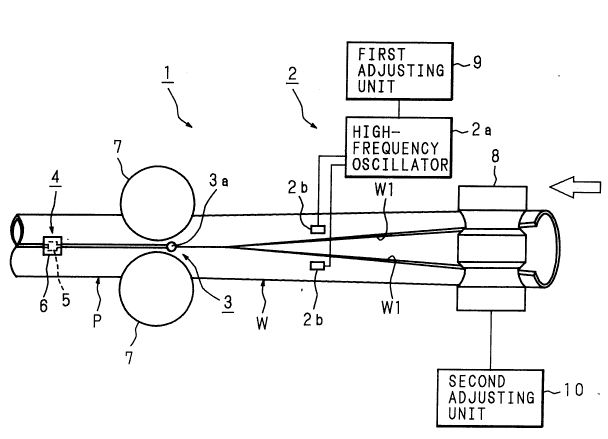
FIG. 1 is a view showing the structure of an apparatus for
producing laser-welded tubes in accordance with the invention. An
apparatus 1 for producing laser-welded tubes has a high-frequency
2170~)~5
_
heating unit 2, a laser welding unit 3 and a bead cutting unit 4
arranged in the transfer direction of metal band W (in the direction of
the hollow arro~ sho~n in the figure) from the upstream side to the
downstream side.
The high-frequency heating unit 2 has a high-frequency oscillator
2a and contact tips 2b, 2b which receive high-frequency current from the
oscillator 2a and supply the high-frequency current to edges W1, W1 of
metal band W before welding. The laser ~elding unit 3 has a laser
oscillator (not shown), a light-guiding tube (not shown) and a ~elding
torch 3a. The bead cutting unit 4 has a fixed cutting tool 5 and a tool
holder 6 for holding the fixed cutting tool 5.
Near the laser welding unit 3, squeeze rolls 7, 7 are provided to
control the abutting shape of edges W1, W1 of metal band W.
Furthermore, on the upstream side of the production line shown in FIG.
1, a breakdown stand having a plurality of horizontal rolls for
performing initial forming including the forming of the edges of metal
band W, a cluster stand having a plurality of side rolls for performing
the forming of the central section of metal band W and a fin-pass stand
having a plurality of horizontal rolls for performing finish forming are
provided in the order from the upstream side. In FIG. 1, only the
horizontal roll 8 on the most downstream side of the fin-pass stand is
sho~n and other sections are not sho~n.
2170n5a
The high-frequency current from the high-frequency oscillator 2a
of the high-frequency heating unit 2 is controlled by power adiustment
at a first adjusting unit 9. The rotation speeds of the rolls of the
above-mentioned stands are adjusted by a second adjusting unit 10. The
second adjusting unit 10 controls the transfer speed of metal band W
(welded tube P) at the production line.
Next, the operation of the apparatus is described below. Metal
band W is transferred in the direction indicated by the hollow arrow in
FIG. 1 and metal band W is gradually formed into a cylindrical shape by
the forming rolls provided on the breakdown stand, cluster stand and
fin-pass stand. Edges W1, W1 of metal band W to be welded are then
preheated by the high-frequency heating unit 2. hfter preheating, edges
W1, W1 of metal band W are ioined by the laser welding unit 3 while
edges W1, W1 are set securely in the abutting condition by the squeeze
rolls 7, 7 to form welded tube P. Welded tube P produced in this way is
transferred to the downstream side and welding beads are cut and
eliminated by the fixed cutting tool 5 of the bead cutting unit 4.
The preheating power at the high-frequency heating unit 2 is
adjusted by the first adjusting unit 9 and the transfer speed of metal
band W (welding tube P) at the production line is adjusted by the second
adjusting unit 10. By these adjustments, edges W1, W1 of metal band W
are preheated by the high-frequency heating unit 2 so that temperature T
~ _ 217~05~
at edges W1, W1 of metal band W before laser welding satisfies the
condition (2) described below.
T > 380 x exp (8.4 x t x al3) ... (2)
where T: Temperature (C) at edges W1, ~1 before laser welding
t: Time (minutes) from the start of laser welding to the cutting
of welding beads
(Transfer time from the laser welding unit 3 to the bead cutting
unit 4)
a: Thickness (mm) of metal band W
FIG. 2 is a graph showing the temperature drops at the welded
sections in various welding methods. By setting the welding point to
"0" when a test material is fed at a transfer speed of 10 m/minute, this
graph shows the distance of the downstream movement from the zero
welding point on the abscissa and shows the temperature at the welding
center on the ordinate. The graph in FIG. 2 shows the temperature
changes in three welding methods: a conventional laser welding method
with preheating not conducted (indicated by solid line a in the figure),
an example of the laser welding method of the invention with preheating
conducted (600C) (indicated by broken line b in the figure) and another
example of the laser welding method of the invention with preheating
conducted (i,100CC) (indicated by dashed line c in the figure). Ho~ever,
the values in the graph are not measured values but plotted values
21700~5
obtained on the basis of calculated heat transfer values. The
preheating temperature in accordance with the invention is the
temperature at the edges of the metal band before laser welding.
In the conventional laser welding method with preheating not
conducted (indicated by line a), the temperature drop is extremely
significant although the temperature at the welding center is the same,
when compared with the two examples of the laser welding method of the
invention with preheating conducted (indicated by lines b and c). This
significant drop is the cause of the problem encountered in the
conventional method, that is, the welding beads are hardened and cannot
be cut.
In the two examples of the laser welding method of the invention
with preheating conducted (indicated by lines b and c), since the
gradient of the temperature drop is gentle, the hardening of the welding
beads can be retarded. ~hen the cutting unit is set at the same
position, although the welding beads generated in the case of the
conventional laser welding method cannot be cut, the welding beads
generated in the case of the two examples of the method of the invention
can be cut and eliminated easily by using a fixed cutting tool. In the
case of non-austenitic steel, the cooling speed of the welding beads is
decreased by preheating and martensitic transformation does not occur,
thereby improving machinability. ~hen the two examples of the laser
2170055
welding method of the invention are compared, it is known that the
gradient of the temperature drop is gentler and the welding beads can be
cut easier in the example conducted at higher preheating temperature
(l,lO~C) than in the example conducted at lower preheating temperature.
Next, the test results of the method for producing laser-~elded
tubes are described below referring to FIGS. 3 to 17. In the tables
shown in FI~S. 3, 4, 6, 7, 9, 10, 12, 13, 15 and 16, the outer diameter
d (mm) of the test material represents the finished outer diameter of
the welded tube. The wall thickness a (mm) of the test material
represents the thickness of metal band W (the finished wall thickness of
the welded tube to be produced). Preheating temperature T (~) represents
the temperature at edges W1, W1 of metal band W before laser welding.
The welding speed (m/sec) represents the transfer speed of metal band W
(welded tube P). Laser output (kW) represents the output of the laser
welding unit 3. The cutting position (m) represents the distance from
the laser welding unit 3 to the bead cutting unit 4. The time to
cutting t (min) represents time from the start of laser welding to the
cutting of welding beads (the time for transferring welded tube P from
the laser welding unit 3 to the bead cutting unit 4). The possibility
of cutting represents whether the cutting of the welding beads can be
done actually ( O) or not (x ) at the bead cutting unit 4. The conformity
to condition represents whether the above-mentioned condition (2) can be
21700~ a
satisfied ( O) or not (x ). Each test result includes a test result
obtained by simulation.
The graphs in FIGS. 5, 8, 11, 14 and 17 are respectively based on
the test results shown in FIGS. 3 and 4, FIGS. 6 and 7, FIGS. 9 and 10,
FIGS. 12 and 13, and FIGS. 15 and 16, and show ~hether cutting is
possible or not ( O : possible, : impossible) ~ith the abscissa used to
represent preheating temperature T and the ordinate used to represent
time to cutting t.
(First test example)
The results of the first test example are shown in FIGS. 3, 4 and
5. The conditions of the first test example are described below.
Test material: Outer diameter d (= 50.8 mm) x wall thickness a (=
6 mm), carbon steel (0.06% C, 1.2% ~n, and Nb and Ni added, for API
Specification, equi~alent to API Specification for Line Pipe grade X60)
Preheating unit: High-frequency heating
Welding unit: Carbon dioxide laser processor
Cutting unit: Fixed cutting tool with cemented carbide chip
(Second test example)
The results of the second test example are shown in FIGS. 6, 7 and
8. The conditions of the second test example are described below.
Test material: Outer diameter d (= 50.8 mm) x ~all thickness a (=
3 mm), carbon steel (0.06% C, 1.2% ~n, and Nb and Ni added, for API
- - 21700~i5
Specification, equivalent to API Specification for Line Pipe grade X60)
Preheating unit: High-frequency heating
Welding unit: Carbon dioxide laser processor
Cutting unit: Fixed cutting tool with cemented carbide chip
(Third test~example)
The results of the third test example are shown in FI~S. 9, 10 and
11. The conditions of the third test example are described below.
Test material: Outer diameter d (= 114 mm) x wall thickness a (= 6
mm), carbon steel (0.06% C, 1.2% Mn, and Nb and Ni added, for API
Specification, equivalent to API Specification for Line Pipe grade X60)
Preheating unit: High-frequency heating
Welding unit: Carbon dioxide laser processor
Cutting unit: Fixed cutting tool with cemented carbide chip
(Fourth test example)
The results of the fourth test example are shown in FIGS. 12, 13
and 14. The conditions of the fourth test example are described below.
Test material: Outer diameter d (= 114 mm) x wall thickness a (=
12.7 mm), carbon steel (0.06% C, 1.2% Mn, and Nb and Ni added, for API
Specification, equivalent to API Specification for ~ine Pipe grade X60)
Preheating unit: High-frequency heating
Welding unit: Carbon dioxide laser processor
Cutting unit: Fixed cutting tool with cemented carbide chip
14
- 21700~5
(Fifth test example)
The results of the fifth test example are shown in FIGS. 15, 16
and 17. The conditions of the fifth test example are described below.
Test material: ~uter diameter d (= 50.8 mm) x wall thickness a (=
6 mm), stainless steel (equivalent to SUS304)
Preheating unit: High-frequency heating
Welding unit: Carbon dioxide laser processor
Cutting unit: Fixed cutting tool with cemented carbide chip
According to the results of the above test examples, the actual
cutting of the welding beads can be done when the above-mentioned
condition (2) is satisfied and cannot be done when the condition (2) is
not satisfied. Accordingly, the welding beads can be cut and eliminated
and the accuracy of the finished dimensions of welded tube P can be
improved by adjusting the degree of preheating at the high-frequency
heating unit 2 and the time t from the start of laser ~elding to the
cutting of the welding beads in view of thickness a of metal band W used
as a test material in the condition (2) so that the temperature T at
edges W1, W1 of metal band W before laser welding can satisfy the
condition (2).
As described above, whether the ~elding beads can be cut or not in
the production of laser-welded tubes greatly depends on the time from
the start of laser welding to the cutting of the welding beads. For
21700~5
this reason, operability can be improved by making the welding bead
cutting position changeable when the laser welding position is fixed.
In the embodiment described below, a movable cutting tool is
provided in view of this point. FIG. 18 shows the structure of the
embodiment. A bead cutting unit 4 having a fixed cutting tool 5 and a
tool holder 6 for holding the cutting tool is mounted on a slider 17.
The slider 17 is movable reciprocally along a horizontal bed 18 in the
direction of the production line. Parts similar to those described in
FIG. 1 are denoted by the same reference numbers and the descriptions
for these parts are omitted.
Netal band W is transferred in the direction indicated by the
hollow arrow in the figure and sub~ected to preheating by a
high-frequency heating unit 2, laser welding by a laser welding unit 3
and cutting by the bead cutting unit 4 in the same way as described in
FIG. 1 to produce a welded tube P. The bead cutting unit 4 (fixed
cutting tool 5) is movable in parallel with the transfer line as shown by
arrows in the figure.
In this embodiment, when the transfer speed is slow for example,
the cutting of the welding beads can be done while the time from the
start of laser welding to the cutting of the welded beads is shortened
substantially by moving the slider 17, on which the bead cutting unit 4
(fixed cutting tool 5) is mounted, toward the laser welding unit 3.
16
- 217~05a
FIG. 19 shows a structure of an apparatus for producing
laser-welded tubes in accordance with another embodiment of the
invention provided with a movable cutting tool. In FIG. 19, parts
similar to those described in FIG. 1 are denoted by the same reference
numbers. In this embodiment, a fixed cutting tool 5 is set at the tip
of a mandrel 21 which is inserted movably in the longitudinal direction
inside tube-shaped metal band W. This embodiment produces the same
effect as the embodiment shown in FIG. 18. In addition, the depth of
cut of the fixed cutting tool 5 can be adjusted by rocking a roll 22
vertically around the fulcrum thereof.
Another embodiment of the cutting tool for cutting the welding
beads is described below. FIGS. 20 (A) to (C) show an embodiment of a
rotary bead cutting tool. In FIG. 20 (A), a rotary cutting tool 30 has
a housing 31, a bearing 32 and a ring cutter 33. As shown in FIG. 20
(C), the ring cutter 33 is set in a condition inclined by angle ~ from
the line perpendicular to the axis of tube-shaped metal band W as viewed
in a single plane. After receiving the pressing force of metal band W,
the ring cutter 33 is rotated on its own axis by a component of the
force. As a result, the ring cutter 33 cuts the outer surface of the
welding bead as shown in FIG. 20 (B).
In the embodiments of the invention, although a fixed cutting tool
5 and a ring cutter 33 ~ere described above as cutting tools, it is
17
- 2170~
needless to say that other cutting tools, such as a milling cutter, can
be used.
Industrial Applicability
As described above, in the method for producing laser-welded tubes
in accordance with the invention, laser welding is performed after the
edges of a metal band to be welded are preheated to form a tube. The
welding beads generated on the outer andJor inner surfaces of the welded
section are cut and eliminated immediately after welding by using a
cutting tool. Preheating before welding restrains the welded section
from quick cooling and prevents the welding beads from hardening
quickly. As a result, although laser welding is used, the welding beads
can be cut and the finished dimensions of the welded tube can have higher
accuracy. In addition, since the welding speed can be raised as the
laser output during laser welding is larger, the selection ranges of the
cutting position and preheating temperature can be extended significantly.
Furthermore, since the cutting tool is set movable in the method
for producing laser-welded tubes in accordance with the invention, the
time from the start of laser welding to the cutting of the welding beads
can be changed. For this reason, when the line speed is low for
example, the welding beads can be cut by moving the cutting tool toward
the welding position.
18