Language selection

Search

Patent 2170246 Summary

Third-party information liability

Some of the information on this Web page has been provided by external sources. The Government of Canada is not responsible for the accuracy, reliability or currency of the information supplied by external sources. Users wishing to rely upon this information should consult directly with the source of the information. Content provided by external sources is not subject to official languages, privacy and accessibility requirements.

Claims and Abstract availability

Any discrepancies in the text and image of the Claims and Abstract are due to differing posting times. Text of the Claims and Abstract are posted:

  • At the time the application is open to public inspection;
  • At the time of issue of the patent (grant).
(12) Patent Application: (11) CA 2170246
(54) English Title: DEVICE TO PUNCH PLASTER TAPES
(54) French Title: DISPOSITIF POUR POINCONNER DES RUBANS D'ENDUIT
Status: Deemed Abandoned and Beyond the Period of Reinstatement - Pending Response to Notice of Disregarded Communication
Bibliographic Data
(51) International Patent Classification (IPC):
  • B26D 03/08 (2006.01)
  • B26D 07/18 (2006.01)
  • B26F 01/10 (2006.01)
(72) Inventors :
  • DOTTA, ANGELO (Italy)
  • DOTTA, ANGELO (Italy)
(73) Owners :
  • PLASTOD S.P.A.
(71) Applicants :
  • PLASTOD S.P.A. (Italy)
(74) Agent: MARKS & CLERK
(74) Associate agent:
(45) Issued:
(86) PCT Filing Date: 1994-08-04
(87) Open to Public Inspection: 1995-03-02
Availability of licence: N/A
Dedicated to the Public: N/A
(25) Language of filing: English

Patent Cooperation Treaty (PCT): Yes
(86) PCT Filing Number: PCT/EP1994/002579
(87) International Publication Number: EP1994002579
(85) National Entry: 1996-02-23

(30) Application Priority Data:
Application No. Country/Territory Date
TO93A 000627 (Italy) 1993-08-25

Abstracts

English Abstract


Device to punch plaster tapes, wherein an adhesive
support layer and a layer of protective material are present,
including a hollow rotating tubular body, having on the
surface thereof a plurality of drilled radial socket punches
realized in a single body with the rotating body, or
alternatively, with removable sectors thereof, equipped with
cutting edges at the hole mouth and with small chips stacks,
inside said holes, cooperating in removing chips of
protective material and contrast and drive means, the plaster
tape being provided passing between said rotating body and
said contrast means synchronously progressing with the
rotating body, said cutting edges and said contrast means
being kept spaced.


French Abstract

La présente invention concerne un dispositif pour perforer des bandes de plâtre se composant d'une couche de support adhésive et d'une couche d'un matériau de protection. Ce dispositif comprend un corps tubulaire rotatif creux (1), dont la surface est pourvue de plusieus poinçons radiaux (6, 6a) percés, du type douille, ne formant qu'une seule pièce avec le corps rotatif (1) ou bien avec des secteurs amovibles (12) de celui-ci, comportant des arêtes de coupe (7, 7a) au niveau de l'embouchure du trou, et des petites piles de pastilles à l'intérieur de ces trous qui coopérent pour retirer les pastilles de matériau protecteur. Le dispositif comporte également un élément de support et d'entraînement (2). La bande de plâtre (3) passe entre le corps rotatif (1) et l'élément de support (2) et avance de manière synchronisée par rapport au corps rotatif (1), tandis qu'un espace est maintenu entre les arêtes de coupe et l'élément de support.

Claims

Note: Claims are shown in the official language in which they were submitted.

CLAIMS
1. Device to punch plaster tapes, wherein an
adhesive support layer (10) and a layer of
protective material (11) are present, including an
hollow rotating tubular body (1) having on the
external surface thereof a plurality of drilled
socket punches (6,6a), communicating with the
rotating body recess (9), equipped with a cutting
edge (7,7a) at the external hole mouth, radially
arranged at the same distance from the rotation
axis of the rotating body (13, and contrast and
drive means (2) cooperating with said rotating body
the plaster tape (3) being provided passing
between said rotating body (1) and said contrast
means (2) synchronously progressing with the
rotating body (1), characterized in that:
said tubular rotating body (1) is realized by
means of a hollow cylinder equipped with spacing
reliefs or shoulders (16,16a) adapted to avoid
contact of the cutting edges (7,7a) of the socket
punches (6,6a) with the contrast means (2) when
punching;
said socket punches (6,6a) form a single body
with the rotating body (1) or, alternatively, with
removable sectors (12) thereof;

the cutting edges (7,7a) of socket punches
(6,6a) and contrast means (2) are kept spaced, said
distance being not greater than the thickness of
the layer of protective material (11);
the hole (83 inside the socket punches (6,6a)
shows, starting from the cutting edges (7,7a), a
section whose diameter and length are respectively
not greater and not lower than the cutting edge
diameter;
small stacks of chips are present inside the
socket punch holes to cooperate, when removing
chips of protective material (11), with the cutting
(7,7) and the hole (8) inside the socket
punches (6,6a).
2. Device to punch plaster tapes, wherein an
adhesive support layer (10) and a layer of
protective material (11) are present, including an
hollow rotating tubular body (1) having on the
external surface thereof a plurality of drilled
socket punches (6,6a), communicating with the
rotating body (1) recess, equipped with a cutting
edge at the external hole mouth, radially arranged
at the same distance from the rotation axis of the
rotating body (1), and contrast and drive means
cooperating with said rotating body (1), the
- 2 -

plaster tape (3) being provided passing between
said rotating body (1) and said contrast means (2)
synchronously progressing with the rotating body
(1), characterized in that:
said tubular rotating body (1) is realized by
means of a hollow cylinder equipped with spacing
reliefs or shoulders (16,16a) adapted to avoid
contact of the cutting edges (7,7a) of the socket
punches (6,6a) with the contrast means (2) when
punching;
said socket punches (6,6a) are stiffly
connected into suitable seats (22) provided in the
rotating body (1), or alternatively into suitable
seats (22) provided in removable sectors of said
rotating body (1);
the cutting edges (7,7a) of socket punches
(6,6a) and contrast means (2) are kept spaced, said
distance being not greater than the thickness of
the layer of protective material (11);
the hole (8) inside the socket punches (6,6a)
shows, starting from the cutting edges (7,7a), a
section whose diameter and length are respectively
not greater and not lower than the cutting edge
diameter;
small stacks of chips (14,14a,14b) are present
- 3 -

inside the socket punch holes (8) to cooperate,
when removing chips of protective material (11),
with the cutting edges (7,7a) and the hole (8)
inside the socket punches (6,6a).
3. Device as claimed in claim 2, characterized in
that said socket punches (6,6a) are stiffly
connected into said seats (22) by pressure and with
the help of welding means.
4. Device as claimed in claim 2, characterized in
that said seats (22) provided in the rotating body
(1) or alternatively in removable sectors thereof,
show a threaded surface and in that said socket
punches (6,6a) are also externally threaded.
5. Device as claimed in claim 1 or 2,
characterized in that the contrast means (2) are
realized by means of a cylinder equipped with
spacing shoulders (17,17a) cooperating with said
opposed spacing shoulders (16,16a) provided in the
hollow cylinder (1), said cylinders (1,2) being
counter-rotating with respect to parallel axes
through peripheral gears (18,19).
6. Device as claimed in claim 1 or 2,
characterized in that the distance between said
cutting edges (7,7a) and said contrast means (2) is
not lower than 50% of the thickness of the layer of
- 4 -

protective material (11).
7. Device as claimed in claim 1 or 2,
characterized in that the chips removed when
punching the tape (3) include a layer of adesive
support (10) only.
8. Device as claimed in claim l or 2,
characterized in that said hollow cylinder (1)
shows an open side to eject the chips deriving from
punching and a side in which a hole is present that
widens inside the cylinder in a cone-shaped duct
(21), said hole communicating with a source of
compressed as to eject the chips.
9. Device as claimed in claim 1 or 2,
characterized in that the arrangement of said
socket punches (6,6a) on said tubular body (1) is
adapted to produce in said tape (3) a plurality of
holes grouped in cyclically repeating
configurations.
10. Device as claimed in claim 1 or 2,
characterized in that the hole (8) inside the
socket punches (6,6a) shows a section, facing the
rotating body (1) recess, whose diameter is greater
than the section facing the cutting edges (7,7a).
- 5 -

Description

Note: Descriptions are shown in the official language in which they were submitted.


~ TO ~ P~SD~ ~SS 2~7324~
The present inventicn deals with a de~ice to
punch plaster tapes.
5It is well k~own that the plaster s~-f~ must
be generally e~lipp~ with perforations to allow
the s~in to y~u~ire.
a 909 634 A;~cln~D~ an ~ for piercing a strip of film Al
ing a f~ ha~ri~lg a layer of ~ A~hl~ Cold_fl~ ng . ~ _~~'ti~n
i~A a _ f - L~a~oS, ~ean~ for pn~ n g --~ 'Pl at ~ 6-~ r~
of ~aid fir8t ~ a econd mem~er ha~ing a pln~ali~y of n~ ~ing fina~rg~
~ean~ for ~ela~ively ~oving ~aid first and ~e~Q~A ~ for ~ n~of ~A~
layer and the film ~n c~r~a~t tbc~ '~h ~y said ~fin~ and mean~ for ~n~A~n~ the
fa-E of said layer to close the oF~nin~ y ~aid f;n~
I- is c~mmon to produce plasters starting from
tape reels ;n~7l~in~ a first layer of ~u~lL
10ma~e~;A~, e~-ir~ wit~ an A~h~sive side, and a
con~ layer of protecti~e ma~iAl, for ~sample
ci~ nAted paper, ~hat ca~ be easily separated
from the fi-st layer, commonly knDwn as liner.
The a~ove-said layers are co~ ed either
15hrough the A~h~ive ~ ~s~uL on the first layer, or
th-ough other m~n~, lea~ing, in this latter case,
the adhesive sur~ace of the first layer free.
After p ln~h i n~ ~ the two layers æe separated
and su~jected to o~her wnrkins steps.
20In orde~ to o~t~ i n the desired pnnr~h i ng~
me~hods can ~e used, that can ~e respec_~rely
f;n~ as hot me~hod and cold method.
The te~m hot method dea 1 s with the tape
punching t~chn;que that provides a slight
-- 1 --

WO ~S1~17 2 2 ~ ~ 3 ~ ~ ~ P~ 91~7s
penetration of heated needles that melt the
adhesive ~u~u L, if thermoplastic, and preserve
the ~liner" substantially integral, thus allowing
it to be used again.
~owever, through this method, scarcely visible
holes are obt~i n~ ~ that can be unequal, irregular
and wrin~l~ due to the un~ven the moplastic
melting when the distance from the hot needle point
increases.
The term cold method deals with the tape
pln~hing ~echnique that provides the use of cutting
means that e~yl~ve the tape, generating circular
holes and removing chips of material including both
plaster and "liner", that therefore, being riddled
as a result, is usually rejected.
Furthermore, this method is usually r~rrie~
out through cutting means with respect to a hard
oo~Llast surface that therefore wears them and
forces the cutting surfaces to be frequently
replaced and sharpened.
Therefore, these surfaces are generally
obt~ine~ through removable bodies to make their
replacement easier.
These embodiments however are complex and
usually allow obt~;n;ng punching densities that are

- - -
W0~0s927 ~ 4 6 PCT~4/02579
not greater than 10 holes per cm~.
Object of the present invention is providing a
- device to generate holes in the plaster surface
that allows cold operations, without appreciably
engravLng the ~liner~, ~eeping it reusable, and
that allows ob~i n i ng at the same time holes that
are even and free from flaws.
Another object of the present invention is
ob~Aini~g a device that allows strongly increasing
the cutting surface life.
lh_~c and other objects are ob~ ;-n~ through
the device to punch plaster tapes, wherein an
adhesive ~u~o-~ layer and a layer of protective
material are present, including an hollow rotating
tubular body having on the surface thereof a
plurality of drilled socket punches, communicating
with the rotating body recess, rA~i~lly arranged at
the same distance from the rotation axis o~ the
rotating body, equipped with a cutting edge at the
hole mouth and contrast and drive means cooperating
with ~aid rotating body, the plaster tape being
provlaed passing between said rotating body and
said contrast means synchronously progressing with
the rotating body, the device being characterized
in that:

W09~ 27 2 1 ~ P~-l/~5~ ly
said socket p~nch~s form a single body with
the rotating body or, alternatively, with remova~le
sectors thereof;
the cutting edges of socket pllnch~s and
. ~LLast means are kept spaced, said distance being
not greater than the thi~n~fiS of the layer of
protective material;
the hole in~ide the socket p~nch~s shows,
starting from the cutting edges, a section whose
diameter and length are respectively not greater
and not lower than the cutting edge diameter;
small stacks of chips are present inside the
~ocket punch holes to cooperate, when removing
chips of protective material, with the cutting
edges and the hole inside the soc~et pnnch~.
A ~c~ embodiment of the device provides the
stiff co~n~ction of the socket punches into
suitable seats provided in the rotating body, or
alternatively, in suitable seats provided in
removable sectors of said rotating body.
A preferred, but not exclusive, embodiment of
the invention will now be described with reference
to the enclosed drawings in which:
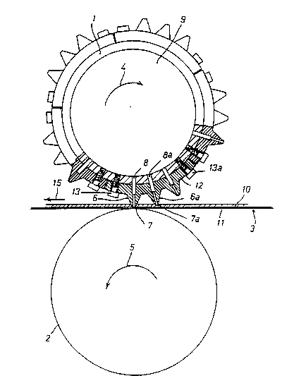
Fig. 1 is a side view, partially in section,
of the device;

W095~5~21 5 2 1 7 ~ 2 4 ~ P.~ 9S10~9
Fig. 2 is a section of a part in the device in
Fig. l;
Fig. 3 is an axial view, partially in section,
of the device in Fig. l;
Fig. 4 is a partial view of a part in a ~econd
embodiment of the device;
Fig. S is a partial view of a part in a third
embodiment of the device.
With reference to Figure 1, the device of the
present Lnvention includes a r~nching cylinAQr 1,
equipped with an int~rn~l rece~s 9, on which there
are assembled, through screws 13, 13a, the
remo~a~le members 12 wherein, in a single body, the
radial cone-sh~n~ socket plnch~s 6, 6a equipped
with the cutting edges 7, 7a are formed.
Said cutting edges 7, 7a are kept spaced with
respect to the surface of the smooth ~l.L-ast
cyl ~ n~r 2 in order to allow the socket plln~h~S 6 ~
6a to penetrate into the plaster tape 3 till they
reach the ~liner~ layer 11, without however
completely pll~ching it, through the adhesive
support layer 10.
For this purpose, as detailed in figure 2, the
distance "d" ~etween the cutting edges 7 and the
smooth surface of the contrast cyl;n~e~ 2 is kept

~ ~ 7 ~ Z ~
WO 95/05g27 r~lJ151~ 1102S79
not lower than 50% of the ~hickness of the "liner~
layer 11.
During rotation of the cyl inA~r 1~ therefore,
pn~hing of the first layer 10 and the sole
engraving of the second layer 11 are carried out
followed by the removal of a chip of material
coming from the first layer 10 only.
The chips 14, 14a, 14b thus formed adhere one
on top of the other due to the adhesive, both if it
is facing the layer 11 and if it is on the free
~urface of the layer 10 and is therefore facing ~he
soc~et punch 6.
The small stacks of chips therefore cooperate
with the surface of the hole (8), inside the socket
punch, in pllnching the tape, making removal of the
following chips easier during rotation of the
cylin~s 1 and 2.
Said rotation occurs in the direction shown ~y
arrows 4 and S, and f avours the tape translation in
the direction shown by arrow 15.
The hole 8 of the socket punch 6 shows a first
section, next to the cutting edges, whose diameter
and length are respectively not greater and not
lower than the diameter of the cutting edge and a
second section, facing the cylin~er recess, whose

WO ~Kg27 ~ ~ 7 ~ 2 ~ P~1/~91/0~7s
diameter is greater than the first section.
In other embodiments that provide the use of
highly resistant steels, the hole inside the socket
~ln~s shows a single section directly
commllnicating with the int~rn~l recess 9 of the
pnn~h i ng cyl i nA~r 1 .
With refe ~a to Figure 3, the pnn~hin~
cylin~r 1 is further e~li~pP~ with ~shoulders~ 16,
16a opposed to other co~Llast ~sho~ rs~ 17, 17a
provided on the cylin~er 2, suitable to keep
cylin~rs 1 and 2 spaced, that are counter-rotating
by means of the mating of gears 18 and 19.
The cylin~ 1 can further by equipped with a
side op~ni~g 20 and with a cone-~h~re~ duct 21
which communicates with a source of compressed air,
not shown, adapted to make chips removal easier.
The ~Cc~ihe~ device is suita~le to operate
with the maximum accuracy and to drill very small
holes (from 0.5 mm to 1.0 mm in diameter) and
closely spaced (2E holes per cm2).
Furthermore, the chips are completely removed
and are not scattered on the tape being worked
making it unusable.
In order to o~tain these results, in addition
to a very accurate adjustment of the distance

WO 9S~"27 . 2~ ~ ~ 0 ~ 4 ~ 02s79
between the cylin~rs~ that can be o~tAine~ as
described, by means of the Ushoulders~, it is
further necessary that the short elastic stacks of
layered chips be present inside the socket punch
holes.
Said short stacks, upon start-up of the
device, can be preformed by r~n~hing a single-layer
tape, with adhesive ~u~ulL only, and by using as
contrast means a cylin~r made of wood or other
ma~rl~l against which the cutting edges of the
socket r~nch~ can operate without being damaged.
With refe~ e to Figure 4, the socket punch
6' is stiffly ronn~cted, for example by pressure
and with the help of welding means, in circular
seats 22 provided in the body of cylin~r l'.
Alternatively, the socket p~Ghe~ can be
stiffly connected, as described in the previous
paragraph, into suitable seats formed in the
removable members 12.
With reference to Fi Æ e 5, the socket punch
6'' is equipped with extern~1 thread adapted to
allow it to be screwed into threaded seats 23
pro~ided in the body of cylin~r 1~.
Alternatively, the socket pl~nc~efi can be
screwed, as described in the previous paragraph,

- WO95l05927
9 ~ ~ 7 û 2 '~ J~31,02579
into suitable threaded seats formed in the
removable members 12.

Representative Drawing
A single figure which represents the drawing illustrating the invention.
Administrative Status

2024-08-01:As part of the Next Generation Patents (NGP) transition, the Canadian Patents Database (CPD) now contains a more detailed Event History, which replicates the Event Log of our new back-office solution.

Please note that "Inactive:" events refers to events no longer in use in our new back-office solution.

For a clearer understanding of the status of the application/patent presented on this page, the site Disclaimer , as well as the definitions for Patent , Event History , Maintenance Fee  and Payment History  should be consulted.

Event History

Description Date
Inactive: IPC expired 2024-01-01
Inactive: IPC from MCD 2006-03-12
Time Limit for Reversal Expired 2002-08-05
Application Not Reinstated by Deadline 2002-08-05
Deemed Abandoned - Failure to Respond to Maintenance Fee Notice 2001-08-06
Inactive: Abandon-RFE+Late fee unpaid-Correspondence sent 2001-08-06
Application Published (Open to Public Inspection) 1995-03-02

Abandonment History

Abandonment Date Reason Reinstatement Date
2001-08-06

Maintenance Fee

The last payment was received on 2000-06-30

Note : If the full payment has not been received on or before the date indicated, a further fee may be required which may be one of the following

  • the reinstatement fee;
  • the late payment fee; or
  • additional fee to reverse deemed expiry.

Patent fees are adjusted on the 1st of January every year. The amounts above are the current amounts if received by December 31 of the current year.
Please refer to the CIPO Patent Fees web page to see all current fee amounts.

Fee History

Fee Type Anniversary Year Due Date Paid Date
MF (application, 3rd anniv.) - small 03 1997-08-04 1997-06-02
MF (application, 4th anniv.) - small 04 1998-08-04 1998-06-15
MF (application, 5th anniv.) - small 05 1999-08-04 1999-07-22
MF (application, 6th anniv.) - small 06 2000-08-04 2000-06-30
Owners on Record

Note: Records showing the ownership history in alphabetical order.

Current Owners on Record
PLASTOD S.P.A.
Past Owners on Record
ANGELO DOTTA
Past Owners that do not appear in the "Owners on Record" listing will appear in other documentation within the application.
Documents

To view selected files, please enter reCAPTCHA code :


To view images, click a link in the Document Description column. To download the documents, select one or more checkboxes in the first column and then click the "Download Selected in PDF format (Zip Archive)" or the "Download Selected as Single PDF" button.

List of published and non-published patent-specific documents on the CPD .

If you have any difficulty accessing content, you can call the Client Service Centre at 1-866-997-1936 or send them an e-mail at CIPO Client Service Centre.


Document
Description 
Date
(yyyy-mm-dd) 
Number of pages   Size of Image (KB) 
Description 1995-03-01 9 271
Abstract 1995-03-01 1 22
Claims 1995-03-01 5 152
Drawings 1995-03-01 3 65
Representative drawing 1999-06-03 1 15
Reminder - Request for Examination 2001-04-04 1 117
Courtesy - Abandonment Letter (Maintenance Fee) 2001-09-03 1 185
Courtesy - Abandonment Letter (Request for Examination) 2001-09-16 1 172
Fees 1996-06-06 1 60
International preliminary examination report 1996-02-22 34 976
Courtesy - Office Letter 1996-03-25 2 26