Language selection

Search

Patent 2170386 Summary

Third-party information liability

Some of the information on this Web page has been provided by external sources. The Government of Canada is not responsible for the accuracy, reliability or currency of the information supplied by external sources. Users wishing to rely upon this information should consult directly with the source of the information. Content provided by external sources is not subject to official languages, privacy and accessibility requirements.

Claims and Abstract availability

Any discrepancies in the text and image of the Claims and Abstract are due to differing posting times. Text of the Claims and Abstract are posted:

  • At the time the application is open to public inspection;
  • At the time of issue of the patent (grant).
(12) Patent: (11) CA 2170386
(54) English Title: LOCKING DEVICE FOR USE WITH SHAFTS OR TUBES
(54) French Title: DISPOSITIF DE VERROUILLAGE DESTINE A DES ARBRES OU DES TUBES
Status: Term Expired - Post Grant Beyond Limit
Bibliographic Data
(51) International Patent Classification (IPC):
  • F16C 35/063 (2006.01)
  • F16C 35/067 (2006.01)
  • F16D 1/08 (2006.01)
(72) Inventors :
  • SWINLEY, GEORGE (United Kingdom)
(73) Owners :
  • NSK EUROPE LTD
(71) Applicants :
  • NSK EUROPE LTD (United Kingdom)
(74) Agent: OYEN WIGGS GREEN & MUTALA LLP
(74) Associate agent:
(45) Issued: 1999-04-27
(86) PCT Filing Date: 1994-09-26
(87) Open to Public Inspection: 1995-04-06
Examination requested: 1996-02-26
Availability of licence: N/A
Dedicated to the Public: N/A
(25) Language of filing: English

Patent Cooperation Treaty (PCT): Yes
(86) PCT Filing Number: PCT/GB1994/002090
(87) International Publication Number: WO 1995009310
(85) National Entry: 1996-02-26

(30) Application Priority Data:
Application No. Country/Territory Date
9319880.2 (United Kingdom) 1993-09-27

Abstracts

English Abstract


A locking device for clamping onto a shaft is
composed of a collar and a ring fitted onto the shaft. The
collar has an end wall and an axial region extending over an
outer inclined contact surface of the ring. The ring and
the collar end wall have inner contact surfaces confronting
the outer surface of the shaft which are separated by
sliding radial surfaces of the collar and the ring. Screw-
threaded elements set in threaded bores in the axial region
of the collar can be tightened against the outer contact
surface of the ring to cause the inner contact surfaces to
exert clamping force on the shaft.


French Abstract

Un dispositif de verrouillage, destiné à être serré sur un arbre (10), est composé d'un collier (19) et d'une bague (13, 17) s'adaptant à l'arbre (10). Le collier (19) comprend une paroi terminale (25) ainsi qu'une région axiale (18) s'étendant sur une surface de contact inclinée (20) de la bague (13, 17). Cette dernière (13, 17), ainsi que la paroi terminale (25) du collier présentent des surfaces de contact internes (9, 22), opposées à la surface externe de l'arbre (10), qui sont séparées par des surfaces radiales coulissantes (50) du collier (19) et de la bague (13, 17). Des éléments filetés (21), ménagés dans des trous filetés (6) dans la région axiale (18) du collier (19), peuvent être resserés contre la surface de contact externe (20) de la bague (13, 17) afin que leurs surfaces de contact internes (9, 22) exercent une force de serrage sur l'arbre (10).

Claims

Note: Claims are shown in the official language in which they were submitted.

THE EMBODIMENTS OF THE INVENTION IN WHICH AN EXCLUSIVE
PROPERTY OR PRIVILEGE IS CLAIMED ARE DEFINED AS FOLLOWS:
1. A device for locking to a component (10, 20)
rotatable about an axis; said device comprising a collar
(19, 190) with an end wall (25, 250) with a surface (22,
280) confronting a surface of the component (10, 120) and
a region (18, 180) extending axially from the end wall, a
ring (13, 17, 170) disposed between the axial region (18,
180) of the collar (19, 190) and the component (10, 120),
the ring (13, 17, 170) having a first surface (9, 240)
confronting the surface of the component (10, 120) and a
second surface (20, 200) which is inclined relative to
the axis of rotation to converge with respect to the axis
of rotation in a direction away from the end wall (25,
250) and several screw-threaded elements (21, 210)
received in threaded bores (6, 220) extending radially
through the axial region (18, 180) of the collar (19)
characterised in that the confronting surfaces
(22,280,9,240) of the collar (19,190) and the ring
(13,17,170) form contact surfaces for contacting the
surface of the component (10,20), the threaded bores
(6,220) are spaced apart relative to the rotational axis
other than at 180° and the screw-threaded elements
(21,210) can be tightened to bear into or against the

second contact surface (20, 200) of the ring (13, 170) to
cause the contact surface (22, 280) of the collar (19)
and the first contact surface (9, 240) of the ring to
exert radial clamping force on the component (10) at
diametrically opposed zones (26, 24,.290, 291).
2. A device according to Claim 1, wherein the contact
surface (22, 280) of the collar (19, 190) and the first
contact surface (9, 240) of the ring (13, 17, 170) lie
closely adjacent to form a continuation of one another.
3. A device according to Claim 2, wherein between the
contact surface (22, 280) of the collar (19, 190) and the
first contact surface (9, 240) of the ring (13, 17, 170)
there are radially abutting contact guide surfaces (50,
350) of the collar (19, 190) and of the ring (13, 17,
170) which slide against one another as the screw-
threaded elements (21, 210) are tightened or released.
4. A device according to Claim 1, 2 or 3 wherein the
screw-threaded elements (21, 210) have end surfaces (23,
230) for contacting the second contact surface (20, 200)
of the ring (13, 17, 170) which are inclined relative to
the axis of rotation.
5. A device according to any one of Claims 1 to 4,
wherein there are two screw-threaded elements (21, 210).

10a
6. A device according to Claim 5, wherein the
threaded bores (6, 220) for receiving the screw-threaded
elements (21, 210) are spaced apart by 120° relative to
the axis of rotation.
7. A device according to any one of Claims 1 to 6,
wherein the second contact surface (23, 230) of the ring

11
(13, 17, 170) has depressions, recesses or blind bores
for receiving the ends of the screw-threaded elements
(21, 210).
8. A device according to and one of Claims 1 to 7,
wherein the rotatable component is a solid shaft or
spindle (10) and the contact surface (22) of the end wall
(25) of the collar (19) is an inner peripheral bore
surface which confronts the exterior surface of the
component (10).
9. A device according to Claim 8, wherein the ring is
formed by an extended region (17) of the inner ring (13)
of a rolling element bearing (11).
10. A device according to any one of Claims 1 to 7,
wherein the component is a hollow shaft or tube (120) and
contact surface (280) of the end wall (250) of the collar
(190) and the first contact surface (240) of the ring
(170) are outer peripheral surfaces which confront the
interior of the component (120) and the axial region
(180) of the collar (190) is disposed radially inwardly
from the interior of the component (120).

Description

Note: Descriptions are shown in the official language in which they were submitted.


WO 95/09310 ~17 0 3 8 g PCTIGB94/02090
LOC~I~G DE~JIC~ FC~ USE w-'n~ S;~A~TS OR TU~ES
TEC;~ AL ~ _ _ LD
The pres2nt inventior. rel2tes o a dev~c~ w;-ich
can be selec.ively locked or clamped tc a shaft o tube.
BACXG~OUND TO T~E I-~VENTION
In .~any mechanical appiicat ons i, is nec2ssar~ to
clamp one component, such as a bearir.g, a sDrocXet or a
pulle~, to a ro.atable comDonent, such as a sha~i or
spindle.
One simple way of clamping the component in place
is to use one or more grub or set screws which engage
with the outer surEace of the shaft. The set scr2ws can
then be received in screw threaded or tapped bores in the
component. In the case OL a bearlng the screws are
placed in tapped bores in the inner ring. The screws
tend to damage the shaft particularly if the-component is
removed from the shaft from time to time. The tlshiening
of the :screws also cause high tensile stresses in the
inner ring and fracturP can occur. The provision oi the
tapped bores also entails addit~onal operations. Another
well known desisn util~zes an eccent-ic collar with a set
screw which when engaged alsc tends to damage the shaft.
Moreover it is not easy to establish the direction Or

r ~ r ~ r ~ I r l ( r
r r r r r r
~ 1 7 0 3 8 6
tightening or loosening when releasing the collar and the
collar is prone to damage. The eccentric collar also
requires specifical machining.
GB-A-978361 describes a clamp with an outer
holding member and an inner ring retained in a recess in
the holding member. A single set screw in a tapped bore
in the holding member forces the ring and the holding
member apart and effects clamping to the shaft.
EP-A-0088589 describes a fluid coupling with a
shaft having a boss portion with a blind opening for
receiving another stub shaft supporting a hub and pulley
assembly in coaxial relation to the coupling shaft. An
adaptor is clamped to the hub assembly and has an axial
region extending around the boss portion. The axial
region of the adaptor has screw-threaded bores in
diametrically opposed positions into which set screws are
fitted. The boss portion has a v-shaped groove into
which the set screws can be engaged to displace the boss
portion and the shaft axially to locate radial end wall
surfaces of the adaptor and the boss portion.
A general object of the present invention is to
provide an improved form of locking device.
~E'~I~ED S~lEET

r ~ ' r ~-
r r ' _ ^ r
. . ^ ~'17~38~
DISCLOSURE OF T~E INVENTION
According to the invention, and as is known from
EP-A-0088~89, there is provided a device for locXlng to a
component rotatable about an axis; said device comprising
a collar with an end wall with a surface confronting a
surface of the component and a region e~tending axially
from the end wall, a ring disposed between the axial
region of the collar and the component the ring having a
first surface confronting the surface of the component
and a second surface which is inclined relative to the
axis of rotation to converge with respect to the axis of
rotation in a direction away from the end wall and
several screw-thre~ded elements received in threaded
bores extending radially through the axial region of the
collar. In accordance with the invention the confronting
surfaces of the collar and the ring form contact surfaces
for contacting the surface of the component, the
threaded bores are spaced apart relative to the
rotational axis other than at 180 and the screw-threaded
elements can be tightened to bear into or against the
second contact surface of the ring to cause the contact
surface of the collar and the first co~tact surface of
rJ~r-~ S'IlEF~

r ~ ~ r
r
- 21703~
3a
the ring to exert radial clamping force on the component
at diametrically opposed zones.
The ends of the screw-threaded elements may have
plane surfaces parallel to the rotational axis or set at
an angle which may have the same sense as the angle of
the second contact surface of the ring. It is possible
to provide shallow depressions, recesses or blind bores
in the second contact surface for receiving the ends of
the screw-threaded elements.
Preferably the surfaces of the collar and the ring
which contact the component and exert clamping force
therein lie directly alongside one another along the axis
of rotation. Between these contact surfaces there may be
radial surfaces of the ring and the collar which engage
on one another and slide against one another as the screw
elements are tightened or released.
The rotatable component may be a shaft or spindle
with the locking device fitted onto its exterior
periphery or a hollow shaft or tube with the locking
device fitted inside. In the first case the contact

~~ WO95/09310 PCT/GB94/02090
217038~
su-f2c~ o~ t;~e c0112- c2n be Sor~ed ~ 2 ~cre in he er,~
wali whilst in the seccnd c~se t:~e cont-c_ surf=c_ o. t~.e
coila~ c-~n Qe Iormed bv ih2 oute_ per ~r.er~ of the end
wali
t is not essen.ia~ .or the rotata~le ccmpcnen. to
~ave a ci-cular c-oss-secticn and the comDonent c-n ha-~e
a poi~gonal cross-section.
The invention may be understood more rea~ ~v and
various other aspects and features o- -he nvent_on may
become apparent, from consideration o- the following
desc_iption and accompanying drawings.
BRIEr D~SCRIPTION OF DRAWINGS
Embodiments of the invention ~ili now be described
by way of examples only, witn reference to the
accompanying drawings therein:
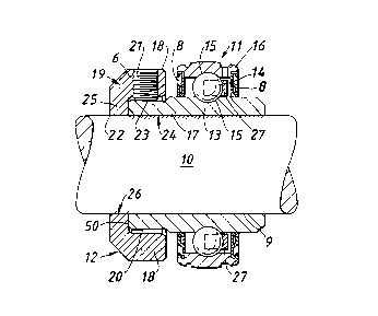
Figure l is a part sectional representation of an
assembly 2mploying a loc~i~g device constructed in
accordar.ce witn the inven.ion and
Eisure 2 is an schematic r2presenLation of another
assembl~ and ioc~ing de~ice constructed in accordanc~
with the invention.
BEST MODES FOR CARRYING OUT THE INVENTION
As shown in F gure l, to a shaft l0 there is

~ WO9S/09310 PCT/GB94l02090
21~0~86
fitted a rol1ing-element bearing 11 and a lockins device
12. T;~e bearins 11 is composed of an extended inne~ rins
13 whicA is to be secured to the sha~t 10 in a non-
rotatabie manner. The ring 13 has an inner contact
surface 9 extending paraliel to the outer per_?heral
surface of the shaft 10. A set of rolling elements,
here i~ the form of balls 14, is disposed in race~ays 15
between the inner ring 13 and an outer ring 16. The
balls i1 are spaced apart round the raceways lS with a
cage 27 and seals 8 are mounted between the rings 1~, 16.
An axial end region 17 of the inner ring 13 is
surrounded by an axi'al portion 18 of a collar 19. The
c0112- 19 has an end wall 25 with a bore for~ing a
contact surface 22 fitted over the shaft 10 with the
surface 22 forming a continuation of the inner contact
surface 9 of the ring 13.
The outer surface of the region 17 of the bearing
inner ring 13 is relieved to provide an outer contact
surface 20 which is tapered to extend at an angle to the
axis of the shaft 10. The surface 20 converges towards
the shaft axis in the direction of the bearing 11. A
typical angle for the surface 20 is 3 and generally an
angle in the range 1 to 5 is preferred.
Two screws 21 are located in threaded bores 6 in

_ WO95/09310 2 1 7 0 3 8 6 PCT/GB94/02090
the a:~zl ~crtion 18 3~ th2 ~0112r i9 dis?osed 120~ apart
a,oun~ the a.~s o~ the ~ha.t 10 . This an~,~ .s not
c-l-ica7 and ma~ vary dependins on the a ?lication The
sc-ews 21 can be displ2cec n~,~ardl~ o. .he Dor-s 5 to
en~ase on the oute_ contact sur~acP 20 c, the ring 13,
In a .nodi.~ed ar-angement the surfac_ 20 hzs ~hailow
recesses or dep.essions or blind bores for loc2tins and
r2cei~ins the ends 23 of t.~e screws 21. The inner r}ng
13 or the bear.ng 11 and tne colla_ 1~ c~n be easlly
fitted onto tne shaft 10 and the screws 21 are then
t.gAtened to some predetermi~ed tor~ue. The ends 23 of
the screws 21, which can be tapered at the same anyle as
the contact surface 20, press on the outer c~ntact
surf~ce 20 to displace the axial end region 17 of the
inner ri~g 13 and the axial portion 18 or the collar 19
radial 1Y apart. This in turn causes diametrically
opposed contact surface zones 24, 26 or the inner contact
surface 9 or the ring 13 and oi' the contaci su_race 22 in
the end wa71 25 o~ the collar 19 to clamp against tne
shaft I0 un~forml~ without caus,ng damage to the shaft
10. To release the loc~ing device 12, the scr~ws 21 are
untightened to permit the collar l9 and the ~earins 11 to
be withdrawn from the shaf~ 10.
The end wall 25 of the collar 19 and the end of

~- WO95/09310 2170386 PCTIGB94/02090
the axial region 17 of the ring 13 abut to form sliding
guide surfaces 50 as the screws 21 are tightened or
released.
Figure 2 depicts another locking device 12 which
is fitted inside a hollow shaft or tube 120. The locking
device is again composed of a collar 190 with an axial
region 180 with two angularly offset threaded bores 220
receiving screws 210. An end wall 250 of the collar has
an outer peripheral contact surface 280 which is parallel
to and confronts an inner surface 300 of the tube 120. A
~ ring 170 has an outer peripheral contact surface 240
which is parallel to and likewise confronts the inner
surface 300 of the tube 120 and an inner contact surface
200 which is tapered~ at an angle to the axis of the tube
120. As with the Figure 1 embodiment, the surface 200
can be inclined at an angle of 1 to 5 and preferably
3 to the axis of the tube 120 and/or the surface 200 can
contain shallow recesses, depressions or blind bores for
receiving the ends 230 of the screws 210.
The device 12 is locked to the tube 120 by
tightening the screws 210 to cause their ends 230 to
displace the axial region 180 of the collar 190 and the
ring 170 radially apart. This in turn causes
diametrically opposed contact surface zones 290, 291 of

~-- WO95/093l0 21703~6 PCT/GB94/02090
the ccntact su ace 280 of the collar en~ ~all 250 and or
the su~.ace 2'0 of the rin5 170 to bear 2gainst t;~e inner
surface 300 of ~ne tube 120 to lock the device in Dlace.
The ring 170 and tne end wail c the coilar 190
have radial faces which abut and establish slidable guide
surfaces 3~0 as the screws 210 a e tighte~ed or
released. The device can be used to pr5vide an aDutment
or location for some other components such as a bearing.
In contrast to some known forms o- lockina device
or mechanisms, a device in accordance with the invention
does not damage the rotatable component and is easily
fitted and removed repeatedly. In the Figure 1
arrangement the inner ring 13 is simply extended and
easily machined in one operation. There is no need to
provide tapped bores in the ring 13. Aiso since no
excessive tensile stresses are create~ on the inner ring
13 there is no danger of fracture for this reason. There
is also no distortion so the raceways for the balls are
unaffected.

Representative Drawing
A single figure which represents the drawing illustrating the invention.
Administrative Status

2024-08-01:As part of the Next Generation Patents (NGP) transition, the Canadian Patents Database (CPD) now contains a more detailed Event History, which replicates the Event Log of our new back-office solution.

Please note that "Inactive:" events refers to events no longer in use in our new back-office solution.

For a clearer understanding of the status of the application/patent presented on this page, the site Disclaimer , as well as the definitions for Patent , Event History , Maintenance Fee  and Payment History  should be consulted.

Event History

Description Date
Inactive: Expired (new Act pat) 2014-09-26
Appointment of Agent Requirements Determined Compliant 2010-11-02
Inactive: Office letter 2010-11-02
Revocation of Agent Requirements Determined Compliant 2010-11-02
Letter Sent 2010-10-28
Revocation of Agent Request 2010-09-29
Appointment of Agent Request 2010-09-29
Inactive: Single transfer 2010-09-29
Letter Sent 2007-11-21
Inactive: Office letter 2007-10-17
Inactive: IPC from MCD 2006-03-12
Grant by Issuance 1999-04-27
Pre-grant 1999-01-14
Inactive: Final fee received 1999-01-14
Notice of Allowance is Issued 1998-07-29
Letter Sent 1998-07-29
Notice of Allowance is Issued 1998-07-29
Inactive: Application prosecuted on TS as of Log entry date 1998-07-23
Inactive: Status info is complete as of Log entry date 1998-07-23
Inactive: Approved for allowance (AFA) 1998-06-02
All Requirements for Examination Determined Compliant 1996-02-26
Request for Examination Requirements Determined Compliant 1996-02-26
Application Published (Open to Public Inspection) 1995-04-06

Abandonment History

There is no abandonment history.

Maintenance Fee

The last payment was received on 1998-08-06

Note : If the full payment has not been received on or before the date indicated, a further fee may be required which may be one of the following

  • the reinstatement fee;
  • the late payment fee; or
  • additional fee to reverse deemed expiry.

Please refer to the CIPO Patent Fees web page to see all current fee amounts.

Owners on Record

Note: Records showing the ownership history in alphabetical order.

Current Owners on Record
NSK EUROPE LTD
Past Owners on Record
GEORGE SWINLEY
Past Owners that do not appear in the "Owners on Record" listing will appear in other documentation within the application.
Documents

To view selected files, please enter reCAPTCHA code :


To view images, click a link in the Document Description column. To download the documents, select one or more checkboxes in the first column and then click the "Download Selected in PDF format (Zip Archive)" or the "Download Selected as Single PDF" button.

List of published and non-published patent-specific documents on the CPD .

If you have any difficulty accessing content, you can call the Client Service Centre at 1-866-997-1936 or send them an e-mail at CIPO Client Service Centre.


Document
Description 
Date
(yyyy-mm-dd) 
Number of pages   Size of Image (KB) 
Abstract 1995-04-06 1 18
Description 1995-04-06 9 291
Cover Page 1996-05-31 1 17
Claims 1995-04-06 4 107
Drawings 1995-04-06 1 27
Representative drawing 1999-04-20 1 9
Cover Page 1999-04-20 1 51
Commissioner's Notice - Application Found Allowable 1998-07-29 1 166
Courtesy - Certificate of registration (related document(s)) 2010-10-28 1 127
Fees 2003-08-14 1 35
Correspondence 1999-01-14 1 41
Fees 1999-07-21 1 37
Fees 1997-07-17 1 43
Fees 2000-08-28 1 34
Fees 2001-08-17 1 36
Fees 1998-08-06 1 45
Fees 2002-08-15 1 38
Fees 2004-08-19 1 39
Fees 2005-09-14 1 33
Fees 2006-08-24 1 37
Correspondence 2007-10-17 1 17
Correspondence 2007-11-21 1 13
Correspondence 2007-11-15 1 30
Fees 2007-09-28 1 58
Correspondence 2010-09-29 3 97
Correspondence 2010-11-02 1 13
Correspondence 2010-11-02 1 20
Fees 1996-07-29 1 46
National entry request 1996-02-26 3 104
National entry request 1996-05-23 1 42
International preliminary examination report 1996-02-26 13 395
National entry request 1996-09-24 5 154
Courtesy - Office Letter 1996-05-23 1 31
Correspondence related to formalities 1996-05-28 1 32
Courtesy - Office Letter 1996-08-23 1 41
Prosecution correspondence 1996-02-26 8 292