Language selection

Search

Patent 2170940 Summary

Third-party information liability

Some of the information on this Web page has been provided by external sources. The Government of Canada is not responsible for the accuracy, reliability or currency of the information supplied by external sources. Users wishing to rely upon this information should consult directly with the source of the information. Content provided by external sources is not subject to official languages, privacy and accessibility requirements.

Claims and Abstract availability

Any discrepancies in the text and image of the Claims and Abstract are due to differing posting times. Text of the Claims and Abstract are posted:

  • At the time the application is open to public inspection;
  • At the time of issue of the patent (grant).
(12) Patent: (11) CA 2170940
(54) English Title: SCREW JACK
(54) French Title: VERIN
Status: Term Expired - Post Grant Beyond Limit
Bibliographic Data
(51) International Patent Classification (IPC):
  • B66F 03/16 (2006.01)
  • B66F 03/08 (2006.01)
  • B66F 03/10 (2006.01)
(72) Inventors :
  • KAWASAKI, YASUJI (Japan)
(73) Owners :
  • KAWASAKI INDUSTRIAL CO., LTD.
(71) Applicants :
  • KAWASAKI INDUSTRIAL CO., LTD. (Japan)
(74) Agent: SMART & BIGGAR LP
(74) Associate agent:
(45) Issued: 1999-08-17
(22) Filed Date: 1996-03-04
(41) Open to Public Inspection: 1996-09-17
Examination requested: 1996-03-04
Availability of licence: N/A
Dedicated to the Public: N/A
(25) Language of filing: English

Patent Cooperation Treaty (PCT): No

(30) Application Priority Data:
Application No. Country/Territory Date
1989/1995 (Japan) 1995-03-16

Abstracts

English Abstract

A screw jack comprising a bed, a case body having a groove formed therein and mounted on an upper surface of the bed, and a thrust bearing mounted on a central area of the upper surface of the bed. A large bevel gear is placed on the bed through the thrust bearing such that a main threaded shaft of the large bevel gear is secured at a lower end thereof to the thrust bearing and erected upwardly therefrom. A small bevel gear carried on the case body through a bearing meshes with the large bevel gear. An outer sleeve is guided along the groove of the case body. A heavy object raising inner sleeve is disposed within the outer sleeve and is guided by the outer sleeve. The main threaded shaft is rotated through the large bevel gear by the small bevel gear which is rotated by an external driver so that a heavy object is raised. The case body is integrally formed of aluminum casting or hard resin.


French Abstract

Un cric à vis comprenant un lit, un boîtier ayant un sillon et monté sur une surface supérieure du lit et un palier de butée monté sur une zone centrale de la face supérieure du lit. Une grande roue conique est placée sur le lit à travers le palier de butée de manière à ce qu'une tige filetée principale de la grande roue conique soit fixée à une extrémité inférieure du palier de butée et érigée vers le haut à partir de celui-ci. Une petite roue conique entraînée sur le corps du boîtier grâce à un roulement s'engrène avec la grande roue conique. Une gaine externe est guidée le long de la rainure du corps du boîtier. Une gaine interne servant à soulever les objets lourds est disposée dans la gaine externe et est guidée par la gaine externe. La tige filetée principale est tournée sur la grande roue conique avec la petite roue conique qui est tournée par un élément externe pour soulever un objet lourd. Le corps du boîtier est intégralement constitué d'aluminium coulé ou de résine dure.

Claims

Note: Claims are shown in the official language in which they were submitted.

9
The embodiments of the invention in which an exclusive
property or privilege is claimed are defined as follows:
1. A screw jack comprising a bed; a case body having a
groove formed therein and mounted on an upper surface of said
bed; a thrust bearing mounted on a central area of the upper
surface of said bed; a large bevel gear placed on said bed
through said thrust bearing such that a main threaded shaft of
said large bevel gear is secured at a lower end thereof to
said thrust bearing and erected upwardly therefrom; a small
bevel gear carried on said case body through a bearing and
meshed with said large bevel gear; an outer sleeve guided
along the groove of said case body; and a heavy object raising
inner sleeve disposed within said outer sleeve and guided by
said outer sleeve; said main threaded shaft being rotated,
through said large bevel gear, by said small bevel gear which
is rotated by an external driver means, so that a heavy object
is raised, wherein said case body is integrally formed of
aluminum casting or hard resin.
2. A screw jack including an outer sleeve guided along a
case body and adapted to guide a heavy object raising inner
sleeve, wherein said outer sleeve is formed by bending a
planar plate into a tubular shape and overlapping and jointing
opposite end faces of said tubular-shaped plate such that the
jointed portion projects outwardly, the projected jointed
portion being fitted in a groove vertically formed in said
case

Description

Note: Descriptions are shown in the official language in which they were submitted.


21'~0~4.a
TITLE OF THE INVENTION
SCREW JACK
BACKGROUND OF THE INVENTION
1. Field of the Invention
This invention relates to a screw jack, which is also known
as j ackscrew, used for raising heavy obj ects such as
automobiles and the like.
2. Brief Description of the Prior Art
1o Heretofore, there are widely used screw j acks of the type
in which a case body portion is of steel plate construction or
of a rigid construction of FC casting. Usually, an outer sleeve
part contacting the case body is a molded product having a
tubular configuration. The outer sleeve is provided with a key
15 groove so that the sleeve will not rotate.
However, the above conventional screw jacks have the
following shortcomings. In the case of the screw jacks of steel
plate construction, the screw jacks are comprised of a
plurality of component parts and therefore; the steps for
20 manufacturing such component parts are required. This '
eventually results in high cost. In the case of the screw jacks
of a rigid construction of FC casting, the weight of final
products tends to be increased.
Moreover, since the component part serving as the outer

21 70940
2
sleeve which contacts the case body is subjected to key groove
treatment in order to prevent the outer sleeve from rotating
with the use of the groove, the steps for manufacturing such
key grooves are required. Furthermore, there is a need of
using an outer sleeve part having a thick wall enough to be
subjected to key groove treatment. The use of an outer sleeve
part having a thick wall makes it even difficult to lower the
manufacturing cost and also to reduce the weight of final
products.
The present invention has been accomplished in view of
the above situation.
SUMMARY OF THE INVENTION
The present invention provides a screw jack which is
simple in construction, light in weight and inexpensive to
manufacture.
According to the present invention, there is provided a
screw jack comprising a bed; a case body having a groove
formed therein and mounted on an upper surface of said bed; a
thrust bearing mounted on a central area of the upper surface
of said bed; a large bevel gear placed on said bed through
said thrust bearing such that a main threaded shaft of said
large bevel gear is secured at a lower end thereof to said
thrust bearing and erected upwardly therefrom; a small bevel
gear carried on said case body through a bearing and meshed
with said large bevel gear; an outer

21709a
3
sleeve guided along the groove of the case body; and a heavy
object raising inner sleeve disposed within the outer sleeve
and guided by the outer sleeve; the main threaded shaft being
rotated, through the large bevel gear, by the small bevel gear
which is rotated by an external driver means, so that a heavy
object is raised, wherein the case body is integrally formed of
aluminum casting or hard resin.
From another aspect of the invention, there is also
provided a screw j ack including an outer sleeve guided along a
1o case body and adapted to guide a heavy object raising inner
sleeve, wherein the outer sleeve is formed by bending a planar
plate into a tubular shape and overlapping and jointing
opposite end faces of the tubular-shaped plate such that the
j ointed portion proj ects outwardly, the proj ected j ointed
portion being fitted in a groove vertically formed in the case
body so that the outer sleeve is prevented from rotating.
The above and other objects and attendant advantages of the
present invention will be apparent to those skilled in the art
from a reading of the following description and claims in
conjunction with the accompanying drawings which constitute
part of this specification.
BRIEF DESCRIPTION OF THE DRAWINGS
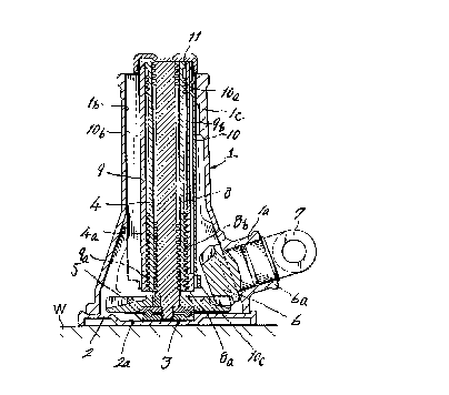
Fig. 1 is a vertical sectional side view of a screw jack
according to one embodiment of the present invention;

~ 17 ~0'~ 4!0
4
Fig. 2 is a side view, partly cut-away, of only a case body
of the screw jack of Fig. 1;
Fig. 3 is a plan view of the case body;
Fig. 4 is a side view of an outer sleeve of the screw jack
of Fig. 1;
Fig. 5 is a plan view of the outer sleeve; and
Fig. 6 is a plan view showing a relation between the case
body and the outer sleeve.
DETAILED DESCRIPTION OF THE PREFERRED EMBODIMENT
One preferred embodiment of a screw j ack according to the
present invention will now be described in detail with
reference to the accompanying drawings.
Reference numeral 1 denotes a case body of the screw jack.
This case body 1 is integrally formed of aluminum casting or
hard resin. Reference numeral 2 denotes a bed of a generally
square shape, which is made of steel material: A recess 2a is
formed in a central area of an upper surface of the bed 2. The
recess 2a is such dimensioned that when the bed 2 is placed on
2o the contacting ground surface W, a bottom surface of the recess
2a is flush with the ground surface W. The case body 1 is '
mounted on the bed 2 with a flange portion of the case body 1
firmly secured to the surface of the bed 2 with rivets ( not
shown ) or the like .
A thrust bearing 3 is disposed in the recess 2a of the bed

2~7~~4~0
2 and a large bevel gear 5 is placed on the thrust bearing 3.
A lower end of a main threaded shaft 4, which is provided with
a threaded portion 4a in an outer periphery thereof, is fixed
to the large bevel gear 5, for example, by means of knocking and
the main threaded shaft 4 is erected upwardly from the large
bevel gear 5. The large bevel gear 5 is meshed with a small
bevel gear 6 on a shaft 6a which is carried on a bearing portion
la integrally formed on the case body 1. The bearing portion la
is located on an inclined line ( not shown ) connecting the
center of the large bevel gear 5 and the center of the shaft 6a.
A handle joint 7 is provided on one end of the shaft 6a.
The handle j oint 7 is rotated by a suitable external driving
means, so that a rotational force is transmitted to the large
bevel gear 5 through the small bevel gear 6.
The threaded portion 4a of the main threaded shaft 4 is
engaged with a threaded portion 8a formed on an inner side of a
lower part of an auxiliary threaded sleeve 8. A threaded
portion 8b on an outer periphery of the auxiliary threaded
sleeve 8 is engaged with a threaded portion 9a formed on an
2o inner side of a lower part of a heavy object raising inner
sleeve 9. The inner sleeve 9 is provided with a groove 9b
formed in an outer periphery thereof and extending in a
vertical direction of the inner sleeve 9. An engagement
portion 10a as later described is formed, by knocking, on an
upper part side of an outer sleeve 10 in such a manner as to

__ 217~~4~
6
project inwardly. The engagement portion 10a is engaged in the
groove 9b in order to prevent rotation of the heavy object
raising inner sleeve 9 and also to guide the inner sleeve 9 when
the inner sleeve 9 is lifted upwardly and downwardly.
A receiving metal piece 11 is rotatably fitted to an upper
end of the heavy object raising inner sleeve 9 through a ring or
the like. The receiving metal piece 11 is adapted to receive a
heavy object, when placed thereon, such as, for example,
automobile or the like. The outer sleeve 10 is formed by a
1o Planar steel plate. The planar steel plate is bent and formed
into a tubular shape. Then, flat surface portions a, and b on
opposite side edges of the steel sheet are overlapped and
welded c such that the welded portion pro j ects outwardly,
thereby defining a key portion 10b. The outer sleeve 10 is
provided on an upper portion of the other side thereof with an
engagement portion 10a for engaging in the groove 9b of the
inner sleeve 9 and on a lower end thereof with an escape
preventive portion 10c protruding outwardly, so that a stopper
lc formed on an inner wall of the case body 1 is engaged
2o therewith, thereby to prevent the outer sleeve 10 from escaping
upwardly by restricting a further upward movement of the outer
sleeve 10.
The key portion 10b of the outer sleeve 10 is fitted in the
vertical groove lb formed in the inner wall of the case body 1,
so that the outer sleeve 10 is prevented from rotation and so

2~70~~0
that the heavy object raising inner sleeve 9 is prevented from
rotation through the engagement portion 10a of the outer sleeve
10.
Owing to the above-mentioned arrangement, when the large
bevel gear 5 of the main threaded shaft 4 erected upwardly from
the thrust bearing 3 located on the center of the bed 2 is
rotated by rotating the small bevel gear 6 which is meshed with
the large bevel gear 5 and carried on the bearing portion la of
the case body 1 with the handle joint 7 disposed outside the
case body 1, the main threaded shaft 4 is rotated through the
main bevel gear 5. Rotation of the main threaded shaft 4 causes
the auxiliary threaded sleeve 8 to gradually move upwardly
because the threaded portion 8a of the auxiliary threaded
sleeve 8 is meshed with the threaded portion 4a of the main
threaded portion 4 and because the auxiliary threaded sleeve 8
is guided by the outer sleeve 10 which is guided by the case
body 1. In this way, the heavy object such as automobile loaded
on the receiving metal piece 11 is finally raised. That is, the
outer sleeve 10 is caused to stop rotation by the case body 1
2o and the heavy abject raising inner sleeve 9 is also caused to
stop rotation through the outer sleeve 10. Accordingly,
rotation of the main threaded portion 4 is transmitted
gradually to the heavy object raising inner sleeve 9, thereby
raising and lowering the heavy object loaded on the receiving
metal piece 11.

2170940
8
As described hereinbefore, the case body is integrally
formed of aluminum resin or hard resin. Accordingly, the
number of component parts and working processes can be reduced.
Also, in the outer sleeve portion, a planar plate is bent and
formed into a tubular shape and the faces of the opposite end
sides of the tubular shaped plate are overlapped and j ointed
such that an outwardly protruded portion thereof forms a key
portion. Accordingly, there is no need of a provision of a key
groove, the material can be made thinner, and the number of
1o manufacturing processes can be reduced. Incidentally, today,
exhaust gas of automobiles comes to be a social problem in view
of air pollution. Thus, there is a strong requirement for
making automobiles lighter in weight as much as possible. The
screw j ack according to the present invention can fully meet
this requirement in the respect that the component parts can be
made light in weight and manufacturing costs of the component
parts can be lowered .
It is to be understood that the form of the invention
herewith shown and described is to be taken as the preferred
embodiment of the same, and that various changes in the shape,
size and arrangement of parts may be resorted to without
departing from the spirit of the invention or the scope of the
subjoined claims.

Representative Drawing
A single figure which represents the drawing illustrating the invention.
Administrative Status

2024-08-01:As part of the Next Generation Patents (NGP) transition, the Canadian Patents Database (CPD) now contains a more detailed Event History, which replicates the Event Log of our new back-office solution.

Please note that "Inactive:" events refers to events no longer in use in our new back-office solution.

For a clearer understanding of the status of the application/patent presented on this page, the site Disclaimer , as well as the definitions for Patent , Event History , Maintenance Fee  and Payment History  should be consulted.

Event History

Description Date
Inactive: Expired (new Act pat) 2016-03-04
Maintenance Request Received 2013-02-15
Inactive: IPC from MCD 2006-03-12
Inactive: Late MF processed 2001-03-08
Grant by Issuance 1999-08-17
Inactive: Cover page published 1999-08-16
Inactive: Final fee received 1999-05-06
Pre-grant 1999-05-06
Notice of Allowance is Issued 1999-03-08
Letter Sent 1999-03-08
Inactive: Application prosecuted on TS as of Log entry date 1999-03-02
Inactive: Status info is complete as of Log entry date 1999-03-02
Inactive: IPC removed 1999-02-09
Inactive: First IPC assigned 1999-02-09
Inactive: IPC assigned 1999-02-09
Inactive: Approved for allowance (AFA) 1999-02-08
Application Published (Open to Public Inspection) 1996-09-17
Request for Examination Requirements Determined Compliant 1996-03-04
All Requirements for Examination Determined Compliant 1996-03-04

Abandonment History

There is no abandonment history.

Maintenance Fee

The last payment was received on 1999-02-15

Note : If the full payment has not been received on or before the date indicated, a further fee may be required which may be one of the following

  • the reinstatement fee;
  • the late payment fee; or
  • additional fee to reverse deemed expiry.

Patent fees are adjusted on the 1st of January every year. The amounts above are the current amounts if received by December 31 of the current year.
Please refer to the CIPO Patent Fees web page to see all current fee amounts.

Owners on Record

Note: Records showing the ownership history in alphabetical order.

Current Owners on Record
KAWASAKI INDUSTRIAL CO., LTD.
Past Owners on Record
YASUJI KAWASAKI
Past Owners that do not appear in the "Owners on Record" listing will appear in other documentation within the application.
Documents

To view selected files, please enter reCAPTCHA code :


To view images, click a link in the Document Description column (Temporarily unavailable). To download the documents, select one or more checkboxes in the first column and then click the "Download Selected in PDF format (Zip Archive)" or the "Download Selected as Single PDF" button.

List of published and non-published patent-specific documents on the CPD .

If you have any difficulty accessing content, you can call the Client Service Centre at 1-866-997-1936 or send them an e-mail at CIPO Client Service Centre.

({010=All Documents, 020=As Filed, 030=As Open to Public Inspection, 040=At Issuance, 050=Examination, 060=Incoming Correspondence, 070=Miscellaneous, 080=Outgoing Correspondence, 090=Payment})


Document
Description 
Date
(yyyy-mm-dd) 
Number of pages   Size of Image (KB) 
Description 1996-06-11 8 277
Abstract 1996-06-11 2 45
Claims 1996-06-11 2 39
Drawings 1996-06-11 4 74
Description 1999-01-26 8 289
Abstract 1999-01-26 1 24
Claims 1999-01-26 1 40
Representative drawing 1998-05-05 1 29
Representative drawing 1999-08-09 1 19
Reminder of maintenance fee due 1997-11-04 1 111
Commissioner's Notice - Application Found Allowable 1999-03-07 1 164
Late Payment Acknowledgement 2001-03-21 1 169
Fees 2003-02-11 1 38
Correspondence 1999-05-05 1 28
Fees 1998-02-18 1 39
Fees 2001-03-07 2 76
Fees 2002-02-06 1 40
Fees 2004-02-08 1 39
Fees 2005-02-13 1 39
Fees 2006-02-13 1 37
Fees 2007-02-25 1 36
Fees 2008-02-28 1 35
Fees 2010-02-08 1 35
Fees 2011-02-15 1 36
Fees 2012-02-06 1 68
Fees 2013-02-14 1 68
Courtesy - Office Letter 1996-03-03 1 26
Prosecution correspondence 1996-03-03 5 136
Courtesy - Office Letter 1996-09-25 1 27
Courtesy - Office Letter 1996-05-22 1 36
Examiner Requisition 1998-03-16 1 40
Prosecution correspondence 1998-09-10 2 76