Language selection

Search

Patent 2171166 Summary

Third-party information liability

Some of the information on this Web page has been provided by external sources. The Government of Canada is not responsible for the accuracy, reliability or currency of the information supplied by external sources. Users wishing to rely upon this information should consult directly with the source of the information. Content provided by external sources is not subject to official languages, privacy and accessibility requirements.

Claims and Abstract availability

Any discrepancies in the text and image of the Claims and Abstract are due to differing posting times. Text of the Claims and Abstract are posted:

  • At the time the application is open to public inspection;
  • At the time of issue of the patent (grant).
(12) Patent Application: (11) CA 2171166
(54) English Title: ROTATABLE BENDING JOINT FOR COLLAPSIBLE PLAYPEN
(54) French Title: JOINT PLIANT TOURNANT AUTOUR D'UN AXE POUR PARCS POUR ENFANTS PLIANTS
Status: Deemed Abandoned and Beyond the Period of Reinstatement - Pending Response to Notice of Disregarded Communication
Bibliographic Data
(51) International Patent Classification (IPC):
  • F16B 12/40 (2006.01)
  • A47D 13/06 (2006.01)
(72) Inventors :
  • SEDLACK, MARK A. (United States of America)
  • STRANSKI, SANDRA KAY (United States of America)
  • SUMSER, DANIEL P. (United States of America)
(73) Owners :
  • GRACO CHILDREN'S PRODUCTS INC.
(71) Applicants :
(74) Agent: SMART & BIGGAR LP
(74) Associate agent:
(45) Issued:
(22) Filed Date: 1996-03-06
(41) Open to Public Inspection: 1996-11-02
Examination requested: 1998-04-28
Availability of licence: N/A
Dedicated to the Public: N/A
(25) Language of filing: English

Patent Cooperation Treaty (PCT): No

(30) Application Priority Data:
Application No. Country/Territory Date
08/432,256 (United States of America) 1995-05-01

Abstracts

English Abstract


An improved rotatable joint of the kind
disclosed in U.S. Pat. No. 5,381,570 for foldable
tubular playpen frames having a step in the tooth of
a recessed sprocket portion in which a connecting
gear rests. In order to unlock the joint one must
move the gear axially inwardly with a pushbutton as
well as relieve the stresses on the joint by lifting
up the tubular bars connected to the joint so that
the gear may slip off the step. In this way an
additional factor of safety is built-in in order to
unlock the joint, and accidental release is reduced.


Claims

Note: Claims are shown in the official language in which they were submitted.

WHAT IS CLAIMED IS:
1. A rotatable hinge comprising:
a first circular portion having a recessed
portion forming a recessed sprocket portion with
sprocket teeth pointing radially inwardly;
a gear having a plurality of gear teeth on
its periphery, said recessed portion sufficiently
deep to substantially receive said gear, said gear
received by said recessed sprocket portion, and said
gear teeth interspaced with said sprocket teeth,
said gear having on one side a protrusion;
a second circular portion having a recess,
said recess receiving said gear protrusion;
said gear interposed between said first
and second circular portions and preventing relative
movement between said first and second circular
portions when said protrusion is received by said
recess;
wherein said sprocket teeth have on one
side thereof a ledge portion extending radially upon
which said gear rests;
wherein to allow said first and second
circular portions of said joint to rotate with
respect to one another and unlock said joint, said
gear is displaced from said ledge portion and
displaced axially within said recessed sprocket
portion, to allow said gear protrusion to disengage
from said recess of said second circular portion.
2. The rotatable hinge according to claim 1,
further comprising a spring disposed between said
recessed sprocket portion and said gear, said spring
axially disposed in the center of said gear and
recessed sprocket portion.

3. The rotatable hinge according to claim 2,
wherein said recess of said second circular portion
has an aperture, a pushbutton having a protrusion
extending through said aperture, said pushbutton
protrusion engaging said gear to displace said gear
axially into said recessed sprocket portion when
said gear is displaced from said ledge portion.
4. The rotatable hinge according to claim 3,
wherein said first and second circular portions are
connected to tubular bars in a horizontal manner to
form a cross-bar frame for a child's playpen, and
said gear is displaced from said ledge portion by
lifting up said bars to relieve the stress on said
hinge.
5. The rotatable hinge according to claim 4,
further comprising an aperture in said gear and said
first and second circular portions, said aperture
receiving a nut and bolt.
6. A rotatable bending joint for bar members
comprising:
a first portion receiving a bar at one end
and having a recessed sprocketed portion, said
sprocketed portion having a plurality of teeth
surrounding and forming said recessed portion and
pointing radially inwardly, said teeth having along
one side thereof a step portion;
a second portion receiving a tubular bar
at one end and having a plurality of indents, said
indents having at least one aperture passing
therethrough and a protrusion connected to a push-
button passing through said apertures, said indents
facing said recessed sprocketed portion;

a gear having on one side a plurality of
detents sized to mate with said indents and of
sufficient width to be received substantially flush
inside said recessed sprocketed portion;
a spring interposed between said gear and
said recessed sprocketed portion and biasing said
gear away from the sprocketed portion;
said gear allowing said first and second
portions of said joint to be rotatably and fixably
secured with respect to one another when said
detents are mated with said indents and when said
gear is resting on said step portion;
whereas to allow said first and second
portions of said joint to rotate with respect to one
another and unlock said joint, said push-button is
depressed and the ends of the first and second
portions are lifted up to allow said gear to alight
from said step portion and allowing said push-button
to push said gear further into said recessed
sprocketed portion of said first portion to allow
said indents to detach from engagement with said
detents.
7. The rotatable bending joint according to claim
6, wherein:
said recessed sprocketed portion is about
13 mm deep, said gear is about 13 mm side, and said
step portion is about 5 mm high from the bottom of
said recessed portion and up to about 1 mm wide
radially.
8. In combination, in a playpen made from tubular
bars supported by a rotatable bending joint, the
invention comprising:

a playpen having a plurality of tubular
bars supported therebetween by a rotatable bending
joint;
said joint having a first portion
receiving one of said plurality bar at one end and
having a recessed sprocketed portion, said
sprocketed portion having a plurality of teeth
surrounding and forming said recessed portion and
pointing radially inwardly, said teeth having along
one side thereof a step portion;
a second portion receiving another of said
tubular bars at one end and having a plurality of
indents, said indents having at least one aperture
passing therethrough and a protrusion connected to a
push-button passing through said apertures, said
indents facing said recessed sprocketed portion;
a gear having on one side a plurality of
detents sized to mate with said indents and of
sufficient width to be received substantially flush
inside said recessed sprocketed portion;
a spring interposed between said gear and
said recessed sprocketed portion and biasing said
gear away from the sprocketed portion;
said gear allowing said first and second
portions of said joint to be rotatably and fixably
secured with respect to one another when said
detents are mated with said indents and when said
gear is resting on said step portion;
whereas to allow said first and second
portions of said joint to rotate with respect to one
another and unlock said joint, said push-button is
depressed and said tubular bars and said ends of the
first and second portions are lifted up to allow
said gear to alight from said step portion and
allowing said push-button to push said gear further

11
into said recessed sprocketed portion of said first
portion to allow said indents to detach from
engagement with said detents.

Description

Note: Descriptions are shown in the official language in which they were submitted.


21 71 1 66
BACKGROUND OF THE INVENTION
This invention relates to an improved
upper play yard or playpen frame hinge or joint of
the kind disclosed in U.S. Pat. No. 5,381,570
(Cheng), incorporated by reference herein in its
entirety.
SUMMARY OF THE INVENTION
The present invention is intended to
provide an improved hinge for a folding playpen
frame.
The improved playpen has the novel feature
of employing an upper frame hinge that requires two
steps to unlock, as opposed to the single step in
the Cheng patent. The frame hinge is composed of
two halves, a gear received in one half, and a
mating gear receiving face with teeth having a
"step" inset in the other half. When the hinge is
locked open, due to the nature of the stresses and
forces within the hinge and frame supporting the
hinge, the gear receiving face supports at this
"step" inset the gear, which prevents rotation of
the gear with respect to its half of the hinge
holding it. To unlock the hinge and allow the frame
to fold, the user must perform two steps, in
contrast to the one step in the Cheng patent: first
the user must push a button in opposition to a coil
spring t-hat releases the gear from the gear
receiving face, as in the Cheng patent, but in
addition the user must lift up on the upper frame
~0 arms that are attache* to the hi-nge to allow the
stress due to gravity and other compressive and
tensile stresses to be relieved and allow the gear
to slip off the "step" inset and allow relative
rotation between the gear and hinge, to allow the
LJPOCJ . PSO

21 71 1 66
2 PATENT
two halves of the hinge to rotate with respect to
one another.
The present invention thus allows an
additional factor of safety over and above the hinge
design disclosed in U.S. Pat. No. 5,381,570.
BRIEF DESCRIPTION OF THE DRAWINGS
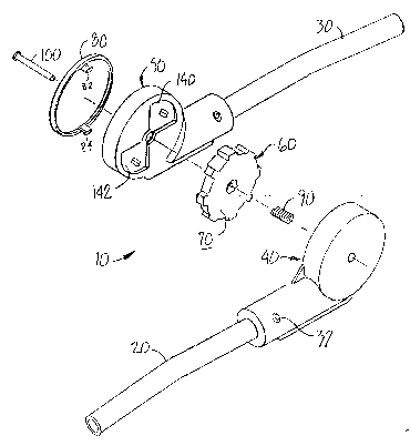
Fig. lA shows an isometric exploded view
of the hinge of the present invention.
Fig. lB is a mirror image of Fig. lA,
viewed from behind.
Fig. 2 shows a top view of the gear
receiving face half of the hinge.
Fig. 3 shows a cut-away portion of Fig. 2.
Fig. 4 shows a perspective view of Fig. 2.
DETAILED DESCRIPTION OF THE PREFERRED EMBODIMENTS
Referring to the figures, there is shown
in Figs. lA and lB a joint or hinge 10 for receiving
and joining two frame bar members 20 and 30 at its
hollow ends, which may have apertures 32 to allow
one to fasten the ends to the bars. The hinge 10
and frame members 20, 30 are configured in a
relation similar to the upper frame 2 and hinge 3
shown in Cheng, U.S. Pat. No. 5,381,570, upon which
the present design is an improvement on, in that the
hinge forms part of a collapsible baby playpen.
Hinge 10 is formed of twa hal~es, a g-ea~
receiving face half 40 and a gear holding face half
50. Gear holding face half 50 holds a gear 60,
which has a first indented side 65 and a second
smooth side 70. The indented side 65 has a pair of
butterfly shaped detents or protrusions, 75, 77,
which are received by the recessed side of the gear
holding face half 50. A push-button 80 with two
LJPOCJ . P50

2 1 71 ~ 66
3 PATENT
prongs 82, 84 fit through apertures 86 in gear
holding face half 50 to push gear 60 in opposition
to a coil spring 90, which is interposed between
gear 60 and the recessed sprocketed face 130 of gear
receiving face halve 40. A nut and bolt arrangement
100 secures and centers the different parts through
a central aperture, but allows axial movement of the
parts.
One important difference between the joint
of present invention and the joint disclosed in the
Cheng patent is the presence of a "step" or ledge
110 inset or seat on a side of each of the recessed
sprocket teeth 120, which point radially inwardly to
the center of the recessed sprocketed face 130 of
the gear receiving face half 40 of joint 10. The
ledge 110 can be seen at the left side of the teeth
120, when viewed as from Figs. 2 and 4. Step 110 is
a ledge spaced 5 mm up from the base of the 13 mm
length of the recessed sprocket teeth 120, as shown
in Fig. 3 (the 13 mm length of the teeth
corresponding to the approximate width of the gear
60), and is about 0.5-1 mm wide circumferentially
along the recessed sprocket tooth, although the
dimensions are not too critical. Gear 60 is about
13 mm in width. The gear 60 rests on the ledge 110,
and when the joint 10 is not locked, the gear 60
fits, if depressed in opposition to coil spring 90,
- substantially entirely fl~sh~within- the recéssed
sprocketed face 130 of gear receiving face 40 and
does not have its butterfly protrusions 75, 77
protrude out (except for a tiny hub portion about
the aperture that receives bolt 100, and which is
received by a mating recess in gear receiving face
40). As shown, the teeth forming the gear are
disposed to fit in the space between the sprocket
LJPOCJ . PSO

2 1 7 1 1 66
4 PATENT
teeth 120. The ledge 110 on the recessed sprocket
teeth 120 thus allows, when the gear 60 rests on the
ledge 110, for the butterfly detents 75, 77 of the
gear 60 to stick out from the width of gear
receiving face 40 (from side 135) and engage the
corresponding indents 140, 142 of gear holding face
half 50. Joint 10 has an outer circular diameter of
about 55 mm.
Operation of like components in joint 10
is generally the same as like components as
described in the Cheng patent, incorporated herein
by its entirety, however, in the present invention,
due to the presence of the step 110 in the teeth 120
of gear receiving face half 40, there is provided an
additional factor of safety when collapsing
(folding) the joint.
In the present invention, the presence of
the step 110 is such that it will just support the
gear 60 so that its detents 75, 77 will eXtend out
from side 135 of gear receiving face half 40 and
thus engage the corresponding butterfly indents 140,
142 of gear holding face half 50. In addition, the
presence of compression coil spring 90 will bias
gear 60 away from recessed sprocketed face 130 of
gear receiving face halve 40.
In the Cheng patent joint one danger that
exists is the accidental folding of the joint and
possible entrapment of an infant's limb if the push
button (push cap 36 in Cheng) is accidentally
depressed. In the present invention, this danger is
mitigated due to the unique function of the step 110
described above, which requires an additional motion
to fold the joint, namely, a lifting up and
relieving of the stresses in the joint. Thus, when
a user desires to collapse (fold) the upper frame of
LJPOCJ . P50

2~ 71 ~ 6~
PATENT
a playpen, the button 80 is depressed, which should
depress, via the two prongs 82, 84 acting on gear
60, the gear 60 and its protrusions 75, 77, to
withdraw inside the recessed sprocketed face 130 of
gear receiving face halve 40, against the bias of
spring 90, and thus disengage the gear detents 75,
77 from the corresponding intents 140, 142 of gear
holding face half 50.
In the present invention, however, unlike
the Cheng patent, the presence of ledge 110 which
the gear ordinarily rests on provides just enough
resistance to the axial movement of the gear when
the pushbutton is depressed to prevent such a
retraction of the gear 60 inside face 130. It has
been found in practice that only by relieving the
stresses accumulated on the joint 10, by lifting up
the joint (as by lifting up the frame bars 20, 30)
is it sufficient to unhitch the gear 60 from
engagement with the ledge 110, and thus allow the
force from the push-button to retract the gear 60 to
inside the face 130 of gear receiving face halve 40,
as explained above. Once this occurs, the joint may
be rotated and the playpen frame bars collapsed.
In this way the present invention provides
an additional factor of safety: in order to unlock
the joint for rotation a user must not only depress
the pushbutton associated with the joint, but also
lift up and relieve the accumulated stresses on the
joint by lifting the frame members attached to the
joint. As it is unlikely an infant will have the
strength to do this, accidental collapsing of the
playpen frame is reduced.
The joint of the present invention may be
constructed from a high-impact engineering
L J POCJ . P50

- 21~1 T6~
6 PATENT
thermoplastic material that can be injection molded
or molded.
As disclosed in the Cheng patent, the
joint of the present invention may be used in a
collapsible playpen, especially to join the
horizontal upper tubular bar members.
The foregoing description is offered for
illustrative purposes only. Numerous modifications
and variations may be readily apparent to those
skilled in the art, while still falling within the
spirit and scope of the invention as claimed herein
below.
LJPOCJ . P50

Representative Drawing
A single figure which represents the drawing illustrating the invention.
Administrative Status

2024-08-01:As part of the Next Generation Patents (NGP) transition, the Canadian Patents Database (CPD) now contains a more detailed Event History, which replicates the Event Log of our new back-office solution.

Please note that "Inactive:" events refers to events no longer in use in our new back-office solution.

For a clearer understanding of the status of the application/patent presented on this page, the site Disclaimer , as well as the definitions for Patent , Event History , Maintenance Fee  and Payment History  should be consulted.

Event History

Description Date
Time Limit for Reversal Expired 2003-03-06
Application Not Reinstated by Deadline 2003-03-06
Deemed Abandoned - Conditions for Grant Determined Not Compliant 2002-03-19
Deemed Abandoned - Failure to Respond to Maintenance Fee Notice 2002-03-06
Notice of Allowance is Issued 2001-09-19
Letter Sent 2001-09-19
Notice of Allowance is Issued 2001-09-19
Inactive: Approved for allowance (AFA) 2001-08-30
Amendment Received - Voluntary Amendment 2001-02-22
Inactive: S.30(2) Rules - Examiner requisition 2001-01-15
Inactive: RFE acknowledged - Prior art enquiry 1998-07-22
Inactive: Application prosecuted on TS as of Log entry date 1998-07-21
Inactive: Status info is complete as of Log entry date 1998-07-21
All Requirements for Examination Determined Compliant 1998-04-28
Request for Examination Requirements Determined Compliant 1998-04-28
Application Published (Open to Public Inspection) 1996-11-02

Abandonment History

Abandonment Date Reason Reinstatement Date
2002-03-19
2002-03-06

Maintenance Fee

The last payment was received on 2001-02-15

Note : If the full payment has not been received on or before the date indicated, a further fee may be required which may be one of the following

  • the reinstatement fee;
  • the late payment fee; or
  • additional fee to reverse deemed expiry.

Please refer to the CIPO Patent Fees web page to see all current fee amounts.

Fee History

Fee Type Anniversary Year Due Date Paid Date
MF (application, 2nd anniv.) - standard 02 1998-03-06 1998-03-06
Request for examination - standard 1998-04-28
MF (application, 3rd anniv.) - standard 03 1999-03-08 1999-03-02
MF (application, 4th anniv.) - standard 04 2000-03-06 2000-02-18
MF (application, 5th anniv.) - standard 05 2001-03-06 2001-02-15
Registration of a document 2001-06-07
Owners on Record

Note: Records showing the ownership history in alphabetical order.

Current Owners on Record
GRACO CHILDREN'S PRODUCTS INC.
Past Owners on Record
DANIEL P. SUMSER
MARK A. SEDLACK
SANDRA KAY STRANSKI
Past Owners that do not appear in the "Owners on Record" listing will appear in other documentation within the application.
Documents

To view selected files, please enter reCAPTCHA code :


To view images, click a link in the Document Description column. To download the documents, select one or more checkboxes in the first column and then click the "Download Selected in PDF format (Zip Archive)" or the "Download Selected as Single PDF" button.

List of published and non-published patent-specific documents on the CPD .

If you have any difficulty accessing content, you can call the Client Service Centre at 1-866-997-1936 or send them an e-mail at CIPO Client Service Centre.


Document
Description 
Date
(yyyy-mm-dd) 
Number of pages   Size of Image (KB) 
Representative drawing 1999-06-28 1 11
Drawings 1998-08-20 2 41
Description 1996-06-21 6 226
Cover Page 1996-06-21 1 17
Abstract 1996-06-21 1 17
Claims 1996-06-21 5 166
Drawings 1996-06-21 2 45
Description 2001-02-22 9 351
Abstract 2001-02-22 1 15
Reminder of maintenance fee due 1997-11-09 1 111
Acknowledgement of Request for Examination 1998-07-22 1 177
Commissioner's Notice - Application Found Allowable 2001-09-19 1 166
Courtesy - Abandonment Letter (Maintenance Fee) 2002-04-03 1 182
Courtesy - Abandonment Letter (NOA) 2002-05-28 1 172
Correspondence 1996-04-23 3 73
Correspondence 2001-07-24 1 13
Fees 1998-03-06 1 43