Language selection

Search

Patent 2171239 Summary

Third-party information liability

Some of the information on this Web page has been provided by external sources. The Government of Canada is not responsible for the accuracy, reliability or currency of the information supplied by external sources. Users wishing to rely upon this information should consult directly with the source of the information. Content provided by external sources is not subject to official languages, privacy and accessibility requirements.

Claims and Abstract availability

Any discrepancies in the text and image of the Claims and Abstract are due to differing posting times. Text of the Claims and Abstract are posted:

  • At the time the application is open to public inspection;
  • At the time of issue of the patent (grant).
(12) Patent: (11) CA 2171239
(54) English Title: ADHESIVE BACKED WINDOW MOLDING
(54) French Title: MOULURE DE FENETRE ADHESIVE
Status: Expired and beyond the Period of Reversal
Bibliographic Data
(51) International Patent Classification (IPC):
  • E06B 3/663 (2006.01)
(72) Inventors :
  • SHERRY, HOWARD W. (United States of America)
(73) Owners :
  • HOWARD W. SHERRY
(71) Applicants :
  • HOWARD W. SHERRY (United States of America)
(74) Agent: BORDEN LADNER GERVAIS LLP
(74) Associate agent:
(45) Issued: 2000-05-09
(22) Filed Date: 1996-03-07
(41) Open to Public Inspection: 1996-09-17
Examination requested: 1996-03-07
Availability of licence: N/A
Dedicated to the Public: N/A
(25) Language of filing: English

Patent Cooperation Treaty (PCT): No

(30) Application Priority Data:
Application No. Country/Territory Date
404,952 (United States of America) 1995-03-16

Abstracts

English Abstract


A plastic molding that is secured between a
window frame and a window. The molding includes an
elongated tubular member with a plurality of sides. An
adhesive strip is secured on two sides of the molding. A
backing releasably covers each of the adhesive strips. Each
backing includes a grippable section for facilitating the
removal of the backing from the adhesive strip.


Claims

Note: Claims are shown in the official language in which they were submitted.

7
WHAT IS CLAIMED IS:
1. A molding for securement between a window
frame and a window comprising:
an elongated tubular member of extruded vinyl
having at least two sides which are at substantially right
angles to each other;
a pair of extensions extending from the periphery
of said tubular member adjacent said two sides to act as
guide means;
a pair of adhesive strips, each strip being
secured along the height of a different one of said sides
adjacent to and in alignment with its respective guide means
for adhering said tubular member to said window frame and
said window, and
means for releasably covering said adhering means.
2. The molding of claim 1 wherein said covering
means includes a pair of release backings, each backing
being positioned over a corresponding one of said adhesive
strips.
3. The molding of claim 2 wherein each of said
release backings includes a grippable section for
facilitating the removal of said backing from said adhesive
strip.
4. A molding for securement between a window
frame and a window comprising:

8
an elongated channel member of extruded vinyl
having at least two sides which are at substantially right
angles to each other;
a pair of extensions extending from the periphery
of said channel member adjacent said two sides to act as
guide means;
a pair of adhesive strips, each strip being
secured along the height of a different one of said sides
adjacent to and in alignment with its respective guide means
for adhering said channel member to said window frame and
said window, and
means for releasably covering said adhering means.
5. The molding of claim 4 wherein said covering
means includes a pair of release backings, each backing
being positioned over a corresponding one of said adhesive
strips.
6. The molding of claim 5 wherein each of said
release backings includes a grippable section for
facilitating the removal of said backing from said adhesive
strip.

Description

Note: Descriptions are shown in the official language in which they were submitted.


2171239
1
ADHESIVE BACKED WINDOW MOLDING
Background of the Invention
The present invention relates to molding that is
secured between a window and window frame and, more
particularly, to such a molding that has adhesive secured
to two sides thereof.
Plastic moldings are commonly secured between a
window frame and a window. The molding fills any existing
space between the frame and the window. Additionally, the
molding may serve as insulation.
A problem with most existing moldings is that
they are relatively difficult to install. For example, some
known moldings are tacked to the window and frame. This
requires a plurality of individual tacks to be hammered
along height of the molding. Other moldings are glued
between the frame and the window. Gluing the molding
requires that careful and meticulous attention be paid in
order to avoid getting glue on the exposed portion of the
molding as well as on the wall and the frame.
Some moldings are equipped with tape or other
adhesive means to secure the molding to the desired area.
See, for example, U. S . Patent Nos . 3, 408, 250 and 4, 614, 347 .
However, these moldings are not designed to be secured to
and between a window frame and a window. Furthermore, these
moldings do not include a means for easily gripping the

2111239
2
paper backing that covers the adhesive so that the backing
can be readily removed while the molding is positioned in
the desired location.
Moreover, many existing moldings cannot
accommodate insulating material. This is due to the fact
that they are solid and, therefore, cannot be filled with
insulating foam or other similar materials.
Summary of the Invention
The present invention is designed to overcome or at
least mitigate the deficiencies of the prior art discussed
above. This invention provides a molding that can be firmly
secured between a window and a window frame. The invention
also provides such a molding that can house insulating
material therein and is relatively flexible.
In accordance with the illustrative embodiments,
demonstrating features and advantages of the present
invention, there is provided a hollow molding made of
flexible material. Insulation material can be inserted in
the molding to provide an energy efficient seal between the
frame and window. Adhesive strips are secured along two
sides of the molding in order to firmly secure the molding
between the frame and the window. Each of the adhesive
strips is covered with a release backing which includes a

2171239
3
grippable section that facilitates the removal of the
backing from the strip.
Other features and advantages will be
readily apparent from the following detailed description of
a preferred embodiment thereof taken in conjunction with
the drawings.
Brief Description of the Drawings
For the purpose of illustrating the invention,
there is shown in the accompanying drawings one form which
is presently preferred; it being understood that the
invention is not intended to be limited to the precise
arrangements and instrumentalities shown.
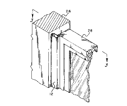
Figure 1 is a partial perspective view of the
present invention;
Figure 2 is a perspective view of the present
invention showing the release paper partially removed, and
Figure 3 is a cross-sectional view taken along
the lines 3-3 of Figure 1.
Detailed Description of the Preferred Embodiment
Referring now to the drawings in detail wherein
like reference numerals have been used throughout the
various figures to designate like elements, there is shown
in the figures an adhesive backed window molding
constructed in accordance with the principles of the
present invention and designated generally as 10.

2171239
4
The window molding 10 includes an elongated
tubular member 12. The tubular member is preferably
comprised of extruded vinyl. However, it can be made in a
number of other ways such as by molding and can be made of
other materials. The tubular member 12 is preferably
substantially rectangular in shape and is preferably 3/4"
long and 1/2" wide. The height of the molding will depend
on the height of the window frame and window. It should be
noted that the tubular member 12 can also be in the form of
an elongated channel, i.e. with a portion of one side or
edge open. Extensions 13 and 15 extend from the periphery
of the tubular member 12 and along the height thereof. The
hollow tubular member 12 can be filled with an insulating
material in order to create an energy efficient seal as
more fully described below.
Pressure sensitive adhesive strips 14 and 16 are
secured to two sides of the tubular member 12 as
illustrated in Figure 2. More specifically, the strips 14
and 16 each have front, rear and opposing side walls. The
front and rear walls of the strips are covered with
adhesive. When securing the strips 14 and 16 to the tubular
member 12, a side wall on each of the strips is placed
against a corresponding extension 13 and 15, respectively,
so that the adhesive covered rear wall is properly aligned
with the side of the tubular member. Accordingly, the
extensions 13 and 15 act as a guide for the accurate
securement of the adhesive strips 14 and 16 to the tubular

2171239
5
member 12. Each of the strips preferably runs the entire
height of the tubular member 12 and is 1/16" thick.
In the preferred embodiment, each of the adhesive
strips 14 and 16 is covered with a protective release
backing 18 and 20. Each of the backings preferably has a
section 22 and 24, respectively, that extends up passed the
top of a corresponding one of the adhesive strips 14 and
16. These upper sections provide a means for readily
gripping the backings and pulling them downward as the
molding is being installed. The backings are preferably
made of polyethylene. However, they can be made of other
material such as paper.
To facilitate an understanding of the principles
associated with the foregoing apparatus, its operation will
now be briefly described. The molding 10 is positioned in
the corner adjacent window frame 26 and window 28.
Thereafter, the upper section 22 of the backing 18 is
pulled downward to expose part of the adhesive strip 16.
The top of the adhesive strip is then placed into contact
with the window frame. As the backing 18 is further
removed, more of the adhesive strip is placed into firm
engagement with the window frame 26 until the entire strip
is secured thereto. It should be noted that a longitudinal
cut can be effectuated along the entire height of the
member 12. This cut gives the molding added flexure which
facilitates the removal of the backings 18 and 20 from
their corresponding adhesive strips 14 and 16.

2171239
6
After the molding 10 is secured to the frame 26,
the upper portion 24 of the backing 20 is then pulled
downwardly so as to expose the adhesive strip 14. The top
of the strip is then pressed into contact with the face of
the window 28. As the backing 20 is further removed, more
of the adhesive strip is placed into firm engagement with
the window 28 until the entire strip is secured thereto.
Before securing the molding in place, the hollow
tubular member 12 can be filled with an insulating material
in order to provide an energy efficient seal between the
window frame 26 and the window 28. This can be achieved by
filling the molding with an insulating foam well known in
the art.
The present invention may be embodied in other
specific forms without departing from the spirit or
essential attributes thereof and accordingly reference
should be made to the appended claims rather than to the
foregoing specification as indicating the scope of the
invention.

Representative Drawing
A single figure which represents the drawing illustrating the invention.
Administrative Status

2024-08-01:As part of the Next Generation Patents (NGP) transition, the Canadian Patents Database (CPD) now contains a more detailed Event History, which replicates the Event Log of our new back-office solution.

Please note that "Inactive:" events refers to events no longer in use in our new back-office solution.

For a clearer understanding of the status of the application/patent presented on this page, the site Disclaimer , as well as the definitions for Patent , Event History , Maintenance Fee  and Payment History  should be consulted.

Event History

Description Date
Time Limit for Reversal Expired 2011-03-07
Letter Sent 2010-03-08
Grant by Issuance 2000-05-09
Inactive: Cover page published 2000-05-08
Inactive: Final fee received 1999-12-21
Small Entity Declaration Determined Compliant 1999-12-21
Pre-grant 1999-12-21
Letter Sent 1999-10-08
Notice of Allowance is Issued 1999-10-08
Inactive: Status info is complete as of Log entry date 1999-10-06
Inactive: Application prosecuted on TS as of Log entry date 1999-10-06
Inactive: Approved for allowance (AFA) 1999-09-28
Application Published (Open to Public Inspection) 1996-09-17
All Requirements for Examination Determined Compliant 1996-03-07
Request for Examination Requirements Determined Compliant 1996-03-07

Abandonment History

There is no abandonment history.

Maintenance Fee

The last payment was received on 2000-02-23

Note : If the full payment has not been received on or before the date indicated, a further fee may be required which may be one of the following

  • the reinstatement fee;
  • the late payment fee; or
  • additional fee to reverse deemed expiry.

Please refer to the CIPO Patent Fees web page to see all current fee amounts.

Fee History

Fee Type Anniversary Year Due Date Paid Date
MF (application, 2nd anniv.) - small 02 1998-03-09 1998-02-18
MF (application, 3rd anniv.) - small 03 1999-03-08 1999-03-03
Final fee - small 1999-12-21
MF (application, 4th anniv.) - small 04 2000-03-07 2000-02-23
MF (patent, 5th anniv.) - small 2001-03-07 2001-02-14
MF (patent, 6th anniv.) - small 2002-03-07 2002-02-11
MF (patent, 7th anniv.) - small 2003-03-07 2003-02-11
MF (patent, 8th anniv.) - small 2004-03-08 2004-02-10
MF (patent, 9th anniv.) - small 2005-03-07 2005-02-08
MF (patent, 10th anniv.) - small 2006-03-07 2006-02-17
MF (patent, 11th anniv.) - small 2007-03-07 2007-02-09
MF (patent, 12th anniv.) - small 2008-03-07 2008-02-13
MF (patent, 13th anniv.) - standard 2009-03-09 2009-02-20
Owners on Record

Note: Records showing the ownership history in alphabetical order.

Current Owners on Record
HOWARD W. SHERRY
Past Owners on Record
None
Past Owners that do not appear in the "Owners on Record" listing will appear in other documentation within the application.
Documents

To view selected files, please enter reCAPTCHA code :


To view images, click a link in the Document Description column. To download the documents, select one or more checkboxes in the first column and then click the "Download Selected in PDF format (Zip Archive)" or the "Download Selected as Single PDF" button.

List of published and non-published patent-specific documents on the CPD .

If you have any difficulty accessing content, you can call the Client Service Centre at 1-866-997-1936 or send them an e-mail at CIPO Client Service Centre.


Document
Description 
Date
(yyyy-mm-dd) 
Number of pages   Size of Image (KB) 
Abstract 1996-06-14 1 14
Description 1996-06-14 6 205
Claims 1996-06-14 2 56
Drawings 1996-06-14 1 36
Cover Page 1996-06-14 1 14
Cover Page 2000-04-11 1 32
Description 1999-09-22 6 207
Claims 1999-09-22 2 51
Representative drawing 1999-08-10 1 12
Representative drawing 2000-04-11 1 13
Reminder of maintenance fee due 1997-11-09 1 111
Commissioner's Notice - Application Found Allowable 1999-10-08 1 164
Maintenance Fee Notice 2010-04-19 1 171
Correspondence 1999-12-21 1 29
Prosecution correspondence 1996-03-07 5 158
Prosecution correspondence 1999-06-22 3 91
Prosecution correspondence 1998-10-19 3 100
Prosecution correspondence 1998-01-16 6 256
Examiner Requisition 1999-01-11 2 60
Examiner Requisition 1998-04-21 2 42
Examiner Requisition 1997-07-18 2 47