Note: Descriptions are shown in the official language in which they were submitted.
2171245
PROCESS AND ARRANGEMENT FOR THE TREATMENT OF SOLID COMBUSTION
RESIDUES IN A COMBUSTION INSTALLATION, IN PARTICULAR IN A
WASTE INCINERATION PLANT
The invention is directed to a process for treating
solid combustion residues in a combustion installation, in
particular in a waste incineration plant, with a furnace grate
and an ash discharges which is connected thereto and is filled
with liquid and has a fall shaft and a ram extractor or push-
out ram and which discharges combustion residues via an
ascending push-out chute. The invention is also directed to
an arrangement for carrying out the process.
In a known process of the type mentioned above, the
combustion residues occurring at the end of a furnace grate in
a combustion installation, especially ashes and cinders, are
discharged by means of a push-out ram via an ascending push-
out chute by an ash discharges which is filled with water. A
fall shaft proceeding from the end of the combustion grate
penetrates into the ash discharges and accordingly closes the
furnace space in an airtight manner. In this so-called
nonwaste-water concept, in which the ash discharges is only
supplied with just enough fresh water that the ashes which are
moistened thereby are discharged, there occurs in the ash
discharges and in the water located therein an equilibrium
concentration with respect to numerous substances and
compounds adhering in the residues, e.g., salt, so that it is
not possible to reduce the concentration of these substances
and compounds. This results in unsatisfactory characteristics
- 1 -
25986-30
2171245
of the ash with respect to disposability or further processing
in the form of construction materials.
In another known ash washing process, water is drawn
off in the rear region of an ash discharger via a run-off and
fresh water is fed into the front discharge shaft. In so
doing, soluble components adhering to the ash are removed by
the water and are extracted from the ash discharger in the
form of sludge behind the rear wall of the fall shaft. Since
these soluble components must submerge to the rear under the
lower edge of the fall shaft, it is understandable that a
considerable portion of these components detached by the water
are discharged along with the ashes via the push-out chute.
Therefore, the characteristics of the ashes with respect to
ease of disposal or further processing to form construction
materials are still not improved.
It is known from EP-C-0 304 412 to subject
combustion residues at least to an alkaline washing and
thereupon also, advantageously, to an acidic washing in order
to remove not only the water-soluble components but also the
heavy metals loosely bonded to the ash. This requires a
relatively elaborate apparatus which is arranged downstream of
the ash discharger.
The object of the present invention is to avoid
expenditure on apparatus as far as possible while at the same
time enabling a treatment of the solid combustion residues
resulting in satisfactory ash characteristics with respect to
ease of disposal and further processing to form construction
materials.
- 2 -
25986-30
21 ~ 1245
According to the invention, this object is met
proceeding from a process of the type mentioned above in that
the washing of the combustion residues is effected in the ash
discharges in which the combustion residues are built up in
the fall shaft by suitable regulation of the discharge rate,
the washing liquid flowing downward through these combustion
residues. The solid combustion residues are preferably built
up beyond the water level in the fall shaft.
As a result of the washing of the solid combustion
residues already in the ash discharges, a large portion of the
known expenditure on apparatus is avoided. The decisive
improvement compared with the washing of ash by means of water
in the conventional sense consists in that the solid
combustion residues are built up or piled up in a tower
formation in the ash discharges so that a substantially longer
period of action is available for the washing liquid and, in
view of this fact alone, improvements can be noticed over the
conventional ash washing even when the washing liquid
comprises only water. The combustion residues are accordingly
extensively freed from pollutants in spite of the low
expenditure on apparatus so that they can be disposed of in
dumps or processed to form construction materials.
A substantial improvement with respect to the
separation of heavy metals is achieved in a further
development of the invention in that a chemical, preferably
acid, e.g., hydrochloric acid or phosphoric acid, is used for
washing, wherein the building up or piling up of the solid
combustion residues in a tower formation, especially so as to
- 3 -
25986-30
~' 21 ~~ ~~~
reach beyond the surface of the liquid, provides particularly
favorable conditions for washing by means of a chemical,
especlally acid, since this tower formation of the combustion
residues provides long paths on which the washing liquid can
proceed through these combustion residues and accordingly
provides long dwelling periods which ensures that heavy metals
will be satisfactorily washed out of the solid combustion
residues without additional vessels or reactors. Due to the
piling up of the combustion residues above the level of
liquid, the washing liquid or chemical first comes into
contact with dry combustion residues, namely in the fall
shaft, in which no particular mechanical action takes place on
the walls of the fall shaft, so that materials can be used for
the construction of the fall shaft which are suitable for use
with stronger acids. Hy the time the washing liquid or
chemical trickles through the combustion residues and reaches
the surface of the liquid, below which the push-out ram is
located, this washing liquid, when acidic, is neutralized by
the alkaline combustion residues to the extent that there is
no longer a risk of a corrosive attack on those portions of
the ash discharges which are located in the liquid and which
are subject to particularly high mechanical wear, so that
these portions need not be manufactured from acid-resistant
material at an impractical cost. Thus, the tower formation of
the solid combustion residues within the fall shaft reaching
above the surface of the liquid is an essential prerequisite
for the use of chemicals, in particular acids, within the ash
discharges.
- 4 -
25986-30
~~ 1
As a result of a further development of the
invention in which fresh water or a chemical, in particular
bases such as sodium hydroxide or phosphates, e.g., the salts
of phosphoric acid, is fed at the discharge end of the ash
discharges in a counterflow to the washing liquid flowing down
through the combustion residues, the bonding of possible
residual pollutants in the combustion residues is improved and
the components which are detached or released during the
washing process and which can settle on the solid combustion
residues again are washed out. In addition, it is also
ensured that the lower part of the ash discharges is not
stopped with fine combustion residues which would prevent
coarser combustion residues from being pushed out. Moreover,
it can also be ensured in this way that those parts of the ash
discharges which cannot be manufactured from acid-resistant
material for reasons pertaining to resistance to wear do not
come into contact with the acidic washing liquid, if used,
since such a situation is prevented by washing liquid in the
form of fresh water or a chemical which is fed in the
counterflow.
In a further development of the invention, the ash
discharges water which is present in the ash discharges and
which is charged with washed out products is drawn off at the
liquid surface adjusted at the lower end of the fall shaft
within the region def fined by the fall shaft or is drawn out of
the ash discharges in order for the sludge which occurs in the
washing process and comprises organic materials, water-soluble
parts and heavy metal components to be reliably removed from
- 5 -
25986-30
217124
the ash discharger. In this way, the ash discharger water or
sludge is reliably drawn off into a draw-off duct, since this
ash discharger water which is charged with fine particles need
no longer flow under the rear wall of the fall shaft into the
rear region of the ash discharger, where this sludge was
formerly drawn off in the conventional ash washing processes.
This manner of drawing off the occurring sludge is
particularly advantageous when using washing liquid in a
counterflow proceeding from the push-out end, since the two
flows meet within the ash discharger in the region of the
surface of the liquid at the lower end of the fall shaft, so
that the components which have already been separated by the
washing liquid trickling down in the fall shaft and those
components which have settled on the combustion residues again
can be carried off and rinsed away by the washing liquid
introduced at the push-out end. As a result of this
advantageous manner of drawing off sludge comprising organic
materials, water-soluble components and heavy metal components
wherein in an advantageous further development of the
invention the draw-off rate is regulated so as to enable solid
particles with particle diameters of up to 2mm to be carried
away, it is ensured that fine particles of ash comprising
particles of up to 2mm will also be drawn off. This is
advantageous because these fine particles contain a
particularly high concentration of pollutants and, above all,
heavy metals.
In a further development of the invention, this ash
discharger water which is drawn out of the ash discharger and
- 6 -
25986-30
'~ 2171245
is charged with washed out products of the type mentioned
above can be fed either to a waste gas purification device
arranged downstream of the combustion process or to a washing
stage for neutralizing acidic waste gases formed in the
combustion process. With respect to the first possibility,
this ash discharger water is sprayed into the waste gas flow,
wherein acidic waste gases can be neutralized on the one hand
and the water component can be expelled on the other hand.
The dry component is fed to the other filter dusts which have
been separated out of the waste gas of the combustion
installation. The second possibility consists in the use of
the ash discharger water for neutralizing acidic waste gases
in wet scrubbers.
Depending upon the chemical composition of the
combustion residues and the washing liquid employed, it may be
advantageous, according to another development of the
invention, to feed at least a portion of the drawn off ash
discharger water back into circulation in the fall shaft for
washing the combustion residues.
The combustion residues falling through the furnace
grate can be advantageously mixed with the ash discharger
water drawn off at the lower end of the fall shaft or from the
ash discharger so that they need not be quenched in an
additional special ash discharger, which would be necessary if
they were reintroduced into the combustion process together
with other still combustible components washed out in the ash
discharger, since it is not possible to return the combustion
residues which have fallen through the furnace grate directly
25986-30
2171245
to the delivery chute because of a possible risk of fire.
The quantity of washing liquid fed into the region
of the upper end of the fall shaft is preferably 0.2 to 20m3
per ton of combustion residues, while the quantity of washing
liquid fed in the counterflow at the push-out end of the ash
discharger is preferably 0.2 to 4m3 per ton of combustion
residues.
The arrangement for carrying out the,process is
characterized by an ash discharger in which a device is
provided in the region of the upper end of the fall shaft for
supplying washing liquid, which device distributes the washing
liquid over the entire cross section of the fall shaft. In
this way, the washing liquid trickles through the combustion
residues in a uniform manner. This washing liquid can be
circulated ash discharged water and/or a chemical, preferably
an acid.
The device for supplying washing liquid can
advantageously comprise spray nozzles which are provided in
the side walls of the fall shaft. This construction not only
permits a uniform trickling of washing liquid through the
combustion residues but also makes it possible for the solid
combustion residues to fall through in a trouble-free manner.
On the other hand, the device for supplying washing
liquid can also comprise perforated pipes traversing the fall
shaft. The holes in the pipes act as spray nozzles. Since
only a few pipes are needed, there is practically no obstacle
in the falling path of the combustion residues.
In a further development of the invention, the parts
_ g _
25986-30
2~ ~~ 2
of the ash discharger subject to particular mechanical stress
by the push-out ram are formed of a material which is wear-
resistant but not acid-resistant and the parts which are
subject to less mechanical stress, in particular the walls of
the fall shaft, are formed of an acid-resistant material
resulting in an economical ash discharger which is
particularly suitable for use with an acidic washing liquid.
Spray nozzles for fresh water or washing liquid are
provided at the push-out side of the ash discharger so that an
additional washing liquid can be fed in a simple manner in the
counterflow to the ash to be discharged, these spray nozzles
enabling a uniform distribution of the liquid to the
combustion residues located on the push-out chute.
In a further development of the invention, the ash
discharger is connected with a hermetically sealed
sedimentation tank or settling tank via a draw-off duct
proceeding from the surface of the liquid within the fall
shaft or within the ash discharger, so that the ash discharger
water occurring in the washing process, including fine
particles floating on the surface, can be drawn off in a
reliable and controllable manner without the risk of secondary
air penetrating into the furnace space which is operated at
below-atmospheric pressure.
The settling tank is advisably connected via vacuum
locks with the collecting hoppers for the combustion residues
falling through the furnace grate since this makes it possible
to quench these combustion residues in a simple manner without
additional ash dischargers.
- 9 -
25986-30
The invention is explained more fully in the
following with reference to embodiment examples of an
arrangement for carrying out the process, which arrangement
comprises an ash discharges.
Figure 1 shows an ash discharges according to the prior art;
Figure 2 shows a first embodiment form of an arrangement for
carrying out the process according to the invention;
Figure 3 shows another embodiment form of an arrangement
according to the invention;
Figure 4 shows a preferred embodiment form of the arrangement
according to the invention.
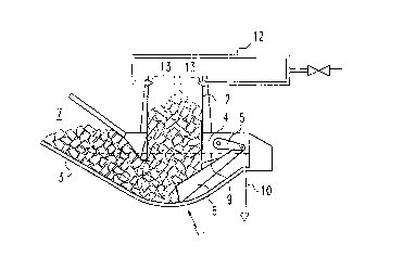
Figure 1 shows a known ash discharges, designated in
its entirety by 1, which has a fall shaft 2, a push-out chute
3, and a push-out ram 6 which is articulated at a driven
swivel arm 5 in the rear region 4 of the ash discharges and
pushes the ash falling from a furnace grate, not shown, into a
push-out shaft 7 via an ascending push-out chute 3. A
constant liquid level 9 is maintained in the ash discharges 1
by means of fresh water which is supplied via an inlet 8, this
liquid level 9 being adjusted at height such that the lower
edge 2a of the fall shaft 2 is immersed in the water.
Although an ash wash is effected in this known ash discharges
by means of water, wherein waste water is drawn off via an
outlet 10 at the rear end 4 of the ash discharges 1, a large
proportion of fine components which do not submerge under the
lower edge of the fall shaft is discharged into the discharge
shaft together with the ashes, which is the cause of the
unsatisfactory ash characteristics mentioned in the
- 10 -
25986-30
2171245
int roduct ion .
The views of the arrangements shown in Figures 2 to
4 show one of the essential features of the invention which
consists in that the ash, designated by 11, is built up in a
tower formation in the ash fall shaft 2, this tower formation
preferably reaching far above the liquid level 9 in the fall
shaft 2. It is noted at this point that all structural
component parts corresponding to those in the ash discharges
according to the prior art have the same reference numbers as
in Figure 1.
As regards the substantial structural component
parts of the ash discharges 1, the relationships shown in the
embodiment form according to Figure 2 are identical to those
shown in Fig. 1. Therefore, only differences between the two
embodiment forms will be discussed. In the embodiment form
shown in Figure 2, the push-out output of the push-out ram 6
is regulated in such a way that the ash 11 forms a vertical
tower in the fall shaft 2. The washing liquid, which can be
water and/or a chemical, preferably an acid, is fed via a
circular line 12 which communicates with spray nozzles which
are provided in the side walls of the fall shaft 2. These
spray nozzles 13 enable the washing liquid to trickle down
through the ash 11 forming a tower within the fall shaft 2
over the entire cross section of the fall shaft 2 . The ash
discharges water which is charged with washed out products is
drawn off via a draw-off line 10 which proceeds from the rear
region 4 of the ash discharges 1.
Figure 3 shows a modification of the embodiment form
- 11 -
25986-30
217124
according to Fig. 2, while the essential parts of the ash
discharger have the same construction. In this embodiment
form, a washing liquid, which can be water or a chemical, in
particular a base or phosphate compounds, is supplied via the
inlet 8 in the discharge shaft 7 of the ash discharger 1. The
ash discharger water which is drawn off from the rear space 4
of the ash discharger via the draw-off line 10 and which is
charged with washed out products is pumped into the circular
line 12 leading to the spray nozzles 13 by a pump 14 via a
line 12a. In so doing, a portion of this charged liquid is
diverted via a valve 15 and another line 16 in order to
maintain the liquid level 9 in the ash discharger 1 at a
determined level on the one hand, this being necessary because
of the supply of liquid through the inlet 8, and, on the other
hand, in order to keep the concentration of entrained sludge
parts, salts and other pollutants from increasing excessively.
In this embodiment form, circulated ash discharger water, to
which a chemical, preferably an acid, can be added via a line
12b opening into the circular line 12, trickles through the
ash 11 which is built up in a tower formation in the fall
shaft 2. The concentration of received pollutant particles is
maintained at a determined level by the constant supply of
liquid at the inlet 8 and the discharge of ash discharger
water via the valve 15 and the line 16.
In the preferred embodiment form of the arrangement
for carrying the process which is shown in Fig. 4, fresh water
or a chemical, preferably a base or a substance from the group
of phosphates, is introduced into the discharge shaft 7 via
- 12 -
25986-30
x 2171245
the inlet 8. As in the embodiment form shown in Fig. 3, a
chemical, preferably an acid, and/or circulated ash discharges
water is used to trickle through the ash il which is built up
in a tower formation in the fall shaft 2. The ash discharges
water is removed from a settling tank 17 which is closed in an
airtight manner and communicates with the ash discharges 1 via
a draw-off duct 18 which proceeds from a region at the height
of the liquid level 9 within the fall shaft 2 or from the ash
discharges located below the latter. The return line 19 which
leads to the spray nozzles 13 in the upper region of the fall
shaft 2 is supplied by means of a pump 20 which sucks the ash
discharges water out of the settling tank 17 at a liquid level
17a which is adjusted close to that point so as to suck out as
few solid particles as possible. A chemical, preferably an
acid, can be fed to the spray nozzles 13 in addition to the
ash discharges water by means of a line 19b opening into the
return line 19. However, the chemical can also be supplied
instead of the ash discharges water if required by the
treatment of the combustion residues. Liquid is drawn out
from the bottom of the settling tank 17, where the ash
discharges water is considerably enriched by the settling
solids particles, via an outlet line 21 in which is arranged a
shut-off valve 22. The amount drawn off is regulated via the
pump 23 in such a way that a draw-off rate is achieved in the
draw-off duct 18 connected with the liquid level 9 within the
fall shaft 2 such that only solids particles up to a particle
- 13 -
25986-30
2171 ~4~
size of 2mm are drawn off. The particles exceeding this
diameter are pushed out along with the other coarse ash parts
via the push-out chute 3 by the push-out ram 6.
- 14 -
25986-30