Language selection

Search

Patent 2171348 Summary

Third-party information liability

Some of the information on this Web page has been provided by external sources. The Government of Canada is not responsible for the accuracy, reliability or currency of the information supplied by external sources. Users wishing to rely upon this information should consult directly with the source of the information. Content provided by external sources is not subject to official languages, privacy and accessibility requirements.

Claims and Abstract availability

Any discrepancies in the text and image of the Claims and Abstract are due to differing posting times. Text of the Claims and Abstract are posted:

  • At the time the application is open to public inspection;
  • At the time of issue of the patent (grant).
(12) Patent Application: (11) CA 2171348
(54) English Title: DEVICE FOR RECEIVING SPLICE CASSETTES FOR OPTICAL WAVEGUIDES, ESPECIALLY IN CABLE SLEEVES
(54) French Title: DISPOSITIF DESTINE A RECEVOIR DES CASSETTES DE RACCORD POUR GUIDES D'ONDES OPTIQUES, PARTICULIEREMENT DANS DES MANCHONS DE CABLE
Status: Deemed Abandoned and Beyond the Period of Reinstatement - Pending Response to Notice of Disregarded Communication
Bibliographic Data
(51) International Patent Classification (IPC):
  • G02B 06/44 (2006.01)
(72) Inventors :
  • FREMGEN, DIETER (Germany)
  • ADAMASZEK, DIETER (Germany)
(73) Owners :
  • WALTER ROSE GMBH & CO KG
(71) Applicants :
  • WALTER ROSE GMBH & CO KG (Germany)
(74) Agent: SMART & BIGGAR LP
(74) Associate agent:
(45) Issued:
(86) PCT Filing Date: 1994-09-26
(87) Open to Public Inspection: 1995-04-13
Availability of licence: N/A
Dedicated to the Public: N/A
(25) Language of filing: English

Patent Cooperation Treaty (PCT): Yes
(86) PCT Filing Number: PCT/GB1994/002082
(87) International Publication Number: GB1994002082
(85) National Entry: 1996-03-07

(30) Application Priority Data:
Application No. Country/Territory Date
P 43 34 022.9 (Germany) 1993-10-06

Abstracts

English Abstract


Using a device (1) for receiving splice cassettes (8a) for optical waveguides,
especially in cable sleeves, comprising a receiving housing (3) and splice cassettes (8a)
arranged therein in the manner of drawers, and comprising openings for the entry and exit of
optical waveguides, cable conductor bunches or the like, a solution is to be provided which
allows the device of the generic kind to be used in a variety of applications irrespective of
the type of cassettes used and while being easy to handle. This is achieved by means of
the fact that the splice cassettes (8a) are arranged on cassette carrying plates (8) which are
located in the receiving housing in such a manner that they can be pushed in and out.


French Abstract

Lorsqu'on utilise un dispositif (1) destiné à recevoir des cassettes de raccord (8a) pour guides d'ondes optiques, particulièrement dans des manchons de câble, ce dispositif comprenant un logement récepteur (3), des cassettes de raccord (8a) disposées à l'intérieur de celui-ci à la manière de tiroirs, ainsi que des ouvertures d'entrée et de sortie de guides d'ondes optiques, de faisceaux conducteurs d'un câble ou analogues, il faut pouvoir trouver une solution qui permette d'utiliser de diverses manières ce dispositif de type général qui doit en outre être facile à manipuler, quel que soit le genre de cassettes utilisé. On a trouvé la solution, celle-ci consistant à disposer les cassettes de raccord (8a) sur des plaques porteuses de cassettes (8) placées dans le logement récepteur de telle manière qu'on peut pousser les cassettes pour les entrer dans le logement ou pour les en sortir.

Claims

Note: Claims are shown in the official language in which they were submitted.

- 6 -
Claims:
1. Device (1) for housing splice cassettes (8a) for optical
waveguides, comprising a receiving housing (3) and splice
cassettes (8a) arranged therein, and comprising openings
for the entry and exit of optical waveguides, cable
conductors or the like, characterised in that the splice
cassettes (8a) are arranged on cassette carrying plates (8)
which are located in the receiving housing in such a manner
that they can be slid and/or rotated in and cut.
2. Device according to claim 1, characterised in that the
cassette carrying plates are provided with fixing elements
(12) in order to form coiled reserves of waveguides or
conductors (11) in addition to the coiled reserves of
waveguides or conductors on the cassettes.
3. Device according to claim 1 or 2, characterised in that one
or more of the cassette carrying plates (8) which can be
pushed into the housing (3) is spatially offset in the
housing (3) from one or more other of the push-in cassette
carrying plates (8).
4. Device according to claim 1, characterised in that it is
possible to fix, by a catch or the like, the cassette
carrying plates (8) at least in a completely pushed-in
position and/or in a pulled-out position.
5. Device according to any one of the preceding claims,
characterised in that the housing (3) is equipped with
mounting projections (4) for fastening the housing inside a
sleeve body (1).
6. Device according to any one of the preceding claims,
characterised in that there is assigned to the housing (3)
in the position of use a potential equalizer (13) for the

- 7 -
fixing of cable shields of incoming and outgoing cables in
order to equalise their potential.
7. Device according to any one of the preceding claims,
characterised in that, in order to arrange the housing (3)
inside a sleeve (1) having cables (11) entering and leaving
at one end, the housing is equipped with supports (4) which
can be mounted on a base plate or a side plate (2) of the
sleeve.
8. Device according to one of the preceding claims,
characterised in that the housing (3) is formed at least in
regions by profiled sheet metal parts (5-7).

Description

Note: Descriptions are shown in the official language in which they were submitted.


W 095/lOOS9 PCT/GB94/02082
2171348
Descri~tion
Device for receiving splice cassettes for optical
waveouides, e~eciallY in cable sleeves
The inv~nti~n relates to a device for receiving splice cassettes
for optical waveguides, especially in cable sleeves.
Various designs of splice cassettes are kncwn, for example fram
EP-A-0 288 808, EP-A-O 531 628, DE-B-0 216 073, EP-A-0 101 970 or
fram the two German laid-open specifications 34 05 309 and 34 13
401.
It is also kncwn to stack a plurality of such cassettes one above
another in cable sleeves, as is disclosed, for example, in PCT/GB
92/02350 of the ~pllr~nt, in which the individual cassettes are
stacked one above another, located in d~L~liate guides and
fastened to one another, for example ky a central screw
arrangement. A device that forms the generic type is known from
EP-A0 204 581.
A disadvantage with the known sslllti~n is that individual
cassettes car~lot be individually adapted to the different
inst~ t;~n requirements, the device cannot be used in a variety
of systems with different cassettes, and necessary reserve cable
cannot readily be ~ccnmm~te~ in the kn3wn cable sleeve.
The inv~nti~n allows a single ~ n of device to be used with
ease in a variety of ~plic~t-~n~ irrespective of the type of
cassettes used.
Thus, the present invention provides a device for housing splice
cassettes for optical waveguides, ccmprising a receiving housing
and splice cassettes arranged therein preferably in manner of
drawers, and comprising openings for the entry and exit of
~optical waveguides, cable conductors or the like, characterised
in that the splice cassettes are auL~lged on cassette carrying

W 095/10059 ~ ~ 7 ~ 3 4 8 - 2 - PCT/GB94/02082
plates which are located in the receiving housing in such a
m~nner that they can be slid and/or rotated, prefera~hly by simply
pushing or pulling by hand, in and out.
With the device according to the invention, it is possihle by
using the cassette carrying plates which can be moved in the
manner of drawers to em~loy the same construction in different
systems for electronic data tr~n~mi~s;~n te~hni~ues, which makes
it easier to m~nllf~ture the latter econ~mic~lly.
In the construction of the invention, provision is made for the
cassette carrying plates to be provided with fixing PlPm~ntS in
order to form coiled reserves of cable in addition to the coiled
reserves of cable on the cassettes.
As a result of this pos~ihility of providing a place for hln~he.
or a place for cables on the cassette carrying plates in
addition, it is ~o~.sihle to m~nipulate the cassettes at a
relatively great distance from a sleeve equipped in that m~nner,
since because of the additional coiled reserves the cassette
itself can be removed from the device and placed, for example, on
a work-bench.
In c~ L~ction, provision is made according to the invention for
a ~L~k~L~ion of the cassette carrying plates which can be pushed
into the housing to be s~ti~lly offset in the housing from
another proportion of the push-in cassette carrying plates, so
that h~n~l;ng is again made easier, since different positi~ning
spaces are produced for the necessary reserve loops of the
in~ming and olltgo;n~ optical waveguides.
In addition to the ~os.~;hility of e~ in~ the housing with
frontal fastening PlPmPnt.~ for msunting purposes, the invention
also provides that the cassette carrying plates are guided in the
housing in the manner of drawers, it being possible to fix at
least the c~m~let~ly pushed-in position and/or the pulled-out
position by a catch or the like, that is to say, each cassette
carrying plate is advantageously held individually in its pushed-

WO9S/10059 _ 3 2 1 7 ~ 3 4 8 PCT/GB94/02082
in position, so that if a housing is in an in~linP~.7 position, forexample, when work is being carried out, the cassettes that are
not being worked on are prevented from f;711ing out even if
further pulled-out positions are fixed, for e ~ nple the half
pulled-out position or the virtually completely pulled-out
position, the locking being effected in such a m~nner that
complete re7noval of that individual cassette carrying plate from
the housing is also made pos.~ih1e. C;7t~ , slide elements or the
like can be provided in this case.
It is also advantageous for a potPnt;~1 eql7~ ;n~ plate for the
fixing of the shields of the in~min~ and outgoing cables to be
~ign~ to the housing in the position of use in order to
e~ e the potPnt;~l, as is also provided by the invention.
The invention is suitable in pr;n~;p1P for every kind of housing,
both for a switch ~1pho~rd and for cable sleeves, one especially
advantageous arrangement of the housing being within a so-called
butt closure, formed for e~nple from a dome-ended sleeve, that
is to say, the cassette carrying plates lie one hPsi~P another in
the longit1l~;n~1 direction in an upright position. For that
purpose, the invention provides that, in order to arrange the
housing in an upright position inside a pot sleeve with cables
entering and leaving at one end, the housing is equipped with
supporting feet which can be m~unted on the base plate or side
plate of the sleeve.
The housing may be m~mlfactured from a wide variety of materials,
one p~ihility being to con~struct at least regions of it from
profiled sheet metal.
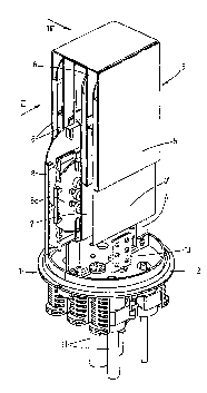
The invPnt;~n is described in detail by way of e~nple below with
reference to the drawings in which:
-
Fig. 1 is a simrlified three-~impn~;onal view of a base plate of a pot
sleeve with the device according to the invention,
Fig. 2 is a side view appro~;m~tPly according to arrow II in Fig. l,

~ ~ 7 - 4 - PCT/GB94/02082
Fig. 3 is a side view appro~im~t~ly according to arrow III in Fig. 1,
and
Fig. 4 is a side view of a cassette outside the housing with ;n~ming
and outgoing conductor bunches.
,
A housing designated 3 is fastened by means of upright feet 4
inside a pot sleeve, generally ~ci~n~ted 1, on which the actual
pot, which is fastened to a base plate ~ign~t~ 2, is not shown
in Fig. 1. In the example shown, the upright feet 4 carry a
rot~ti~n~1ly symmetrical housing made of profiled sheet metal
parts 5 to 7 which, as shcwn in Fig. 2, are so arranged in
r~l~ti~n to one another that compdLL~ Ls are formed into which
the cassette carrying plates designated 8, which carry the
cassettes ~ci~n~ted 8a, are inserted in the m~nner of drawers.
In the example shown, the ~l~m~ntc of the receiving housing 3 are
equipped at their lower edge with flanges 9 which form drawer-
runners for the cassette carrying plates 8, the shape being such
that slot openings 10 for the passage of the optical waveguides,
cable h mrh~s or the like entering and leaving the splice
cassettes are formed at the lower edge with the neighb3uring
wall. The in~m;ng and olltg~in~ optical waveguides and conductor
hln~h~c are generally designated 11 in the Figures, irrespective
of whether they are h m~h~c of m~ny or few conductors or are
single cable conductors or the like.
As will be seen, for example, from Fig. 3 and Fig. 4, each
cassette carrying plate 8 has a plurality of ~l~m~ing projections
12 h~hin~ which the in~ming and outgoing fibre hln~h~ or cables
11 can be laid in large reserve loops in such a manner that, for
example in Fig. 4, downwardly oriented loops lla are formed
which, however, depending upon the position of the cassette 8,
could also be formed at the top.
As will be seen especially from Fig. 1, there is ~Csi~n~ to the
device 3 a so-called potential ~ licin~ plate 13 to which all

W o 95/10059 PCT/GB9~/02082
~ - 5 - 2171348
the shields of the ;nc~mi~ and outgoing cables may be connected
for the purpose of ~lAl;cin~ the potential. If desired, an
earthing cable (not shcwn) can also be contacted there.
The described en~xxl~nent of the invention can, of course, still
be mo~ifie~ in m~ny respects withc~t departing from the
underlying concept. For example, in partic~ r, as has already
keen m~nti~ne~ above, the invention is not limited to a pot
sleeve ~ n and a hori~nt~l arrangement can be provided in the
same m~nner, for example in a through-sleeve, there may be many
different s~;n~ between adjacent cassette carYying plates, and
so on.

Representative Drawing
A single figure which represents the drawing illustrating the invention.
Administrative Status

2024-08-01:As part of the Next Generation Patents (NGP) transition, the Canadian Patents Database (CPD) now contains a more detailed Event History, which replicates the Event Log of our new back-office solution.

Please note that "Inactive:" events refers to events no longer in use in our new back-office solution.

For a clearer understanding of the status of the application/patent presented on this page, the site Disclaimer , as well as the definitions for Patent , Event History , Maintenance Fee  and Payment History  should be consulted.

Event History

Description Date
Time Limit for Reversal Expired 1999-09-27
Application Not Reinstated by Deadline 1999-09-27
Deemed Abandoned - Failure to Respond to Maintenance Fee Notice 1998-09-28
Application Published (Open to Public Inspection) 1995-04-13

Abandonment History

Abandonment Date Reason Reinstatement Date
1998-09-28

Maintenance Fee

The last payment was received on 1997-08-21

Note : If the full payment has not been received on or before the date indicated, a further fee may be required which may be one of the following

  • the reinstatement fee;
  • the late payment fee; or
  • additional fee to reverse deemed expiry.

Patent fees are adjusted on the 1st of January every year. The amounts above are the current amounts if received by December 31 of the current year.
Please refer to the CIPO Patent Fees web page to see all current fee amounts.

Fee History

Fee Type Anniversary Year Due Date Paid Date
MF (application, 3rd anniv.) - standard 03 1997-09-26 1997-08-21
Owners on Record

Note: Records showing the ownership history in alphabetical order.

Current Owners on Record
WALTER ROSE GMBH & CO KG
Past Owners on Record
DIETER ADAMASZEK
DIETER FREMGEN
Past Owners that do not appear in the "Owners on Record" listing will appear in other documentation within the application.
Documents

To view selected files, please enter reCAPTCHA code :


To view images, click a link in the Document Description column. To download the documents, select one or more checkboxes in the first column and then click the "Download Selected in PDF format (Zip Archive)" or the "Download Selected as Single PDF" button.

List of published and non-published patent-specific documents on the CPD .

If you have any difficulty accessing content, you can call the Client Service Centre at 1-866-997-1936 or send them an e-mail at CIPO Client Service Centre.


Document
Description 
Date
(yyyy-mm-dd) 
Number of pages   Size of Image (KB) 
Abstract 1995-04-12 1 55
Claims 1995-04-12 2 58
Description 1995-04-12 5 216
Drawings 1995-04-12 3 79
Representative drawing 1997-06-12 1 12
Courtesy - Abandonment Letter (Maintenance Fee) 1998-10-25 1 184
Fees 1996-08-27 1 58
International preliminary examination report 1996-03-06 10 176