Language selection

Search

Patent 2171377 Summary

Third-party information liability

Some of the information on this Web page has been provided by external sources. The Government of Canada is not responsible for the accuracy, reliability or currency of the information supplied by external sources. Users wishing to rely upon this information should consult directly with the source of the information. Content provided by external sources is not subject to official languages, privacy and accessibility requirements.

Claims and Abstract availability

Any discrepancies in the text and image of the Claims and Abstract are due to differing posting times. Text of the Claims and Abstract are posted:

  • At the time the application is open to public inspection;
  • At the time of issue of the patent (grant).
(12) Patent Application: (11) CA 2171377
(54) English Title: BILLET GUIDING UNIT OF A CONTINUOUS CASTING PLANT FOR THIN SLABS
(54) French Title: ELEMENT DE GUIDAGE DES BILLETTES POUR USINE DE COULEE EN CONTINU DE BRAMES
Status: Deemed Abandoned and Beyond the Period of Reinstatement - Pending Response to Notice of Disregarded Communication
Bibliographic Data
(51) International Patent Classification (IPC):
  • B22D 11/16 (2006.01)
  • B22D 11/128 (2006.01)
(72) Inventors :
  • STREUBEL, HANS (Germany)
(73) Owners :
  • SMS SCHLOEMANN-SIEMAG AKTIENGESELLSCHAFT
(71) Applicants :
  • SMS SCHLOEMANN-SIEMAG AKTIENGESELLSCHAFT (Germany)
(74) Agent: RICHES, MCKENZIE & HERBERT LLP
(74) Associate agent:
(45) Issued:
(22) Filed Date: 1996-03-08
(41) Open to Public Inspection: 1996-09-26
Availability of licence: N/A
Dedicated to the Public: N/A
(25) Language of filing: English

Patent Cooperation Treaty (PCT): No

(30) Application Priority Data:
Application No. Country/Territory Date
195 11 113.3 (Germany) 1995-03-25

Abstracts

English Abstract


A billet guiding unit of a continuous casting plant for thin
slabs includes guide rolls supported on oppositely located frames,
wherein the frames are tensioned relative to each other against
stop surfaces by means of tension rods. Hydraulic cylinders for
extending or stretching the tension rods are mounted between
corresponding stop surfaces of the frames. The distance between
oppositely located rows of rolls of the frames are corrected by
determining a lower deviation side of the slab by carrying out a
continuous measurement of the thickness of the slab sides, by
determining from the difference of the dimensions the required
extension of the tension rods on the lower deviation side and by
applying to the hydraulic cylinders the pressure required for the
extension of the tension rods.


Claims

Note: Claims are shown in the official language in which they were submitted.

I claim:
1. A billet guiding unit of a continuous casting plant for
thin slabs, the guiding unit comprising oppositely located frames,
guide rolls mounted on each frame, the frames having stop surfaces
facing each other, tension rods connected to the stop surfaces for
tensioning the frames, and hydraulic cylinders mounted between the
stop surfaces of the frame for extending the tension rods.
2. The guiding unit according to claim 1, wherein the
hydraulic cylinders are annular hydraulic cylinders surrounding the
tension rods.
3. The guiding unit according to claim 2, comprising a
hydraulic pressure source connected to the annular hydraulic
cylinders through a multiple-way valve, and control means for
controlling the multiple-way valve, the control means comprising a
slab thickness measuring device and a computer.
4. The guiding unit according to claim 1, wherein the
hydraulic cylinders on one side of the guiding unit are annular
hydraulic cylinders surrounding the tension rods.
11

5. A method of adjusting a distance between oppositely
located frames of a billet guiding unit of a continuous casting
plant for thin slabs, the guiding unit including oppositely located
frames, guide rolls mounted on each frame, the frames having stop
surfaces facing each other, tension rods connected to the stop
surfaces for tensioning the frames, and hydraulic cylinders mounted
between the stop surfaces of the frame for extending the tension
rods, the method comprising determining a lower deviation side of
the slab by carrying out a continuous measurement of the thickness
of the slab sides, determining from the dimensional difference a
required extension of the tension rods on the lower deviation side,
and applying a pressure to the hydraulic cylinders for effecting
the required extension of the tension rods.
12

Description

Note: Descriptions are shown in the official language in which they were submitted.


--- 21 71377
R~CK~O~ND OF THE lNv~.~lON
1. Field of the Invention
The present invention relates to a billet guiding unit of a
continuous casting plant for thin slabs, wherein guide rolls are
supported on oppositely located frames, wherein the frames are
tensioned relative to each other against stop surfaces by means of
tension rods.
2. Description of the Related Art
DE-A1 26 12 094 discloses a billet guiding unit in which the
frame supporting the bearings of the guide rolls are connected by
several tension rods, wherein the distance between the frame
components is determined by an annular bracket mounted on each
tension rod and by spacer members. For tensioning the frame, two
sleeves supported against each other with inclined screw-shaped
surfaces are rotated by a pressure medium cylinder. When the
billet becomes jammed, the bushings are rotated in an unloading
direction.

--~ 21 713i7
DE-Al 43 06 853 discloses a billet guiding unit of a
continuous casting plant for continuous casting and rolling of thin
slabs, wherein the frames of the billet guiding unit are connected
by piston/cylinder units, and wherein an annular hydraulic cylinder
and a spacer member each are arranged between stop surfaces of the
upper and lower frames. By means of this unit, the guide rolls
supported on the frames are adjusted into three defined positions
during continuous casting.
The known billet guiding units described above are complicated
and subject to malfunction.

_ ~ 21 71377
SUMMARY OF THE lNV~.~ lON
In view of the above-described prior art, the present
invention deals with the following problem: Aside from the state
of alignment of the billet guide unit, the actual distance between
the guide rolls of the above-described billet guiding unit which
determines the cross section of the billet during the casting
operation depends on the pretensioned condition of the tension rods
and on the temperature. Consequently, the thin slabs emerging from
the billet guiding unit may have wedge-shaped cross sectional
shapes because the cross section of the billet is determined by the
actual spacing between the rolls in the area of final
solidification.
Therefore, it is the primary object of the present invention
to provide a billet guiding unit with frames which are mechanically
tensioned relative to each other by means of tension rods, in which
it is possible during casting to compensate in a simple manner for
an inaccurate alignment or unequal thermal expansion or wear of the
guide rolls mounted on the frames which results in thickness
variations over the cross section of the slab.

21 71 377
In accordance with the present invention, hydraulic cylinders
for extending or stretching the tension rods are mounted between
corresponding stop surfaces of the frames.
The configuration according to the present invention makes
possible a compensation of thickness variations over the cross
section of the slab with a simple, mechanically structured and,
thus, operationally safe billet guiding unit. In this connection,
the invention is based on the finding that the differences in
dimension can be fully compensated by the achievable extension of
the tension rods.
In accordance with another feature of the present invention,
the annular hydraulic cylinders surround the tension rods between
the stop surfaces of the frames.
The annular hydraulic cylinders are connected to a hydraulic
pressure source through a valve which is supplied with a control
signal from a control means including a slab thickness measuring
device and a computer.
The distance between oppositely located rows of rolls of the
frames are corrected by determining a lower deviation side of the
slab by carrying out a continuous measurement of the thickness of

~_~ 2171377
the slab sides, by determining from the difference of the
dimensions the required extension of the tension rods on the lower
deviation side and by applying to the hydraulic cylinders the
pressure required for the extension of the tension rods.
When the pressure is applied to the hydraulic cylinders, it is
advantageous to take into consideration the state of pretensioning
of the tension rods and/or the position of the pool tip within the
billet guiding segment.
The various features of novelty which characterize the
invention are pointed out with particularity in the claims annexed
to and forming a part of the disclosure. For a better
understanding of the invention, its operating advantages, specific
objects attained by its use, reference should be had to the drawing
and descriptive matter in which there are illustrated and described
preferred embodiments of the invention.

_ 21 71377
BRIEF DESCRIPTION OF THE DRAWING
In the drawing:
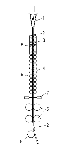
Fig. 1 is a schematic illustration of a continuous casting
plant for thin slabs;
Fig. 2 is a side view, on a larger scale, of a portion of the
billet guiding unit of the continuous casting plant;
Fig. 3 is a top view, also on a larger scale and partially in
section, of the billet guiding unit in billet travel direction; and
Fig. 4 is a schematic view showing the annular hydraulic
cylinders and the control circuit for the annular hydraulic
cylinders.

2l7l377
DESCRIPTION OF THE PREFERRED EMBODIMENT
In the continuous casting plant schematically illustrated in
Fig. 1 of the drawing, a continuous casting mold 1 for thin slabs
2 is followed by a billet guiding unit including a first section 3
and a second section 4. The cast slab 2 is conveyed by means of a
driving unit 5 through the guiding unit 3, 4 formed by support
guide rolls 6, wherein a liquid core of the billet is finally
solidified as a result of cooling when emerging from the section 4.
The thickness profile of the slab 2 is determined by measuring
devices 7 underneath the guiding unit 3, 4. The slab 2 is then
deflected by means of deflection roll 8.
As illustrated in Figs. 2 and 3 of the drawing, the support
guide rolls 6 of the second section 4 of the guiding unit are
mounted on oppositely located frames 9, 10. The frames 9, 10 have
on both sides thereof essentially cylindrical end pieces 11, 12
with openings 13 for tension rods 14, 15. At their ends projecting
out of the frames 9, 10, the tension rods 14, 15 are provided with
nuts 16 for adjusting the desired distance between the support
guide rolls 6 and, thus, the thickness of the solidified slab 2.

, 2l7l377
Annular hydraulic cylinders 17, 18 surrounding the tension
rods 14, 15 are arranged between corresponding end faces of the end
pieces 11, 12. The frames 9, 10 are pretensioned through the
tension rods 14, lS and nuts 16 against the annular hydraulic
cylinders 17, 18 with a force which is greater than the ferrostatic
force acting on the guiding unit from the proportional section of
the not fully solidified slab.
A control unit illustrated in Fig. 4 is provided for the
annular hydraulic cylinders 17, 18. The components of the control
unit are measuring devices 7, computer 19, hydraulic pressure
source 21, pressure limiting valve 22 and multiple-way valve 20.
From a difference of ~imen~ions determined by the measuring devices
7, the computer forms signals for the pressure limiting valve 22
and the multiple-way valve 20 for applying pressure to the annular
hydraulic cylinders 17 or 18 located at the lower deviation side of
the slab 2 for obtaining a uniform cross sectional profile in
accordance with the required extension of the tension rods 14 or 15
and for obtaining a uniform cross section of the slab.
The invention is not limited to the illustrated embodiment.
In particular, for changing the size, exchangeable spacer members
can be mounted between the frame surfaces, wherein conventional

-
21 7137~
hydraulic cylinders are arranged outside of and separately from the
tension rods 14, 15 between the frames 9, 10.
While specific embodiments of the invention have been shown
and described in detail to illustrate the inventive principles, it
will be understood that the invention may be embodied otherwise
without departing from such principles.

Representative Drawing
A single figure which represents the drawing illustrating the invention.
Administrative Status

2024-08-01:As part of the Next Generation Patents (NGP) transition, the Canadian Patents Database (CPD) now contains a more detailed Event History, which replicates the Event Log of our new back-office solution.

Please note that "Inactive:" events refers to events no longer in use in our new back-office solution.

For a clearer understanding of the status of the application/patent presented on this page, the site Disclaimer , as well as the definitions for Patent , Event History , Maintenance Fee  and Payment History  should be consulted.

Event History

Description Date
Inactive: IPC from MCD 2006-03-12
Application Not Reinstated by Deadline 2004-03-08
Time Limit for Reversal Expired 2004-03-08
Inactive: Status info is complete as of Log entry date 2003-05-20
Inactive: Abandon-RFE+Late fee unpaid-Correspondence sent 2003-03-10
Deemed Abandoned - Failure to Respond to Maintenance Fee Notice 2003-03-10
Letter Sent 1998-05-15
Reinstatement Requirements Deemed Compliant for All Abandonment Reasons 1998-05-04
Deemed Abandoned - Failure to Respond to Maintenance Fee Notice 1998-03-09
Application Published (Open to Public Inspection) 1996-09-26

Abandonment History

Abandonment Date Reason Reinstatement Date
2003-03-10
1998-03-09

Maintenance Fee

The last payment was received on 2002-02-28

Note : If the full payment has not been received on or before the date indicated, a further fee may be required which may be one of the following

  • the reinstatement fee;
  • the late payment fee; or
  • additional fee to reverse deemed expiry.

Patent fees are adjusted on the 1st of January every year. The amounts above are the current amounts if received by December 31 of the current year.
Please refer to the CIPO Patent Fees web page to see all current fee amounts.

Fee History

Fee Type Anniversary Year Due Date Paid Date
MF (application, 2nd anniv.) - standard 02 1998-03-09 1998-05-04
Reinstatement 1998-05-04
MF (application, 3rd anniv.) - standard 03 1999-03-08 1999-02-19
MF (application, 4th anniv.) - standard 04 2000-03-08 2000-02-18
MF (application, 5th anniv.) - standard 05 2001-03-08 2001-02-22
MF (application, 6th anniv.) - standard 06 2002-03-08 2002-02-28
Owners on Record

Note: Records showing the ownership history in alphabetical order.

Current Owners on Record
SMS SCHLOEMANN-SIEMAG AKTIENGESELLSCHAFT
Past Owners on Record
HANS STREUBEL
Past Owners that do not appear in the "Owners on Record" listing will appear in other documentation within the application.
Documents

To view selected files, please enter reCAPTCHA code :


To view images, click a link in the Document Description column (Temporarily unavailable). To download the documents, select one or more checkboxes in the first column and then click the "Download Selected in PDF format (Zip Archive)" or the "Download Selected as Single PDF" button.

List of published and non-published patent-specific documents on the CPD .

If you have any difficulty accessing content, you can call the Client Service Centre at 1-866-997-1936 or send them an e-mail at CIPO Client Service Centre.

({010=All Documents, 020=As Filed, 030=As Open to Public Inspection, 040=At Issuance, 050=Examination, 060=Incoming Correspondence, 070=Miscellaneous, 080=Outgoing Correspondence, 090=Payment})


Document
Description 
Date
(yyyy-mm-dd) 
Number of pages   Size of Image (KB) 
Representative drawing 1998-03-23 1 6
Abstract 1996-06-16 1 23
Description 1996-06-16 9 212
Claims 1996-06-16 2 49
Drawings 1996-06-16 3 29
Reminder of maintenance fee due 1997-11-10 1 111
Courtesy - Abandonment Letter (Maintenance Fee) 1998-04-05 1 187
Notice of Reinstatement 1998-05-14 1 170
Reminder - Request for Examination 2002-11-11 1 115
Courtesy - Abandonment Letter (Maintenance Fee) 2003-04-06 1 179
Courtesy - Abandonment Letter (Request for Examination) 2003-05-19 1 167
Fees 1998-05-03 1 50
Courtesy - Office Letter 1996-03-31 1 16