Note: Descriptions are shown in the official language in which they were submitted.
W095/07857 ~ ~ 7 I ~ ~ 1 PCT~S94/10362
1 APPARATUS AND METHOD FOR REDUCING THE REDOX POTENTIAL OF SUBSTANCES
4 FIELD OF THE INVENTION
6 The present invention relates to apparatus and
7 methods for controlling the redox potential and the
8 characteristics of hydrogen contained in water and to
9 various uses of such water.
11
12 BACKGROUND OF THE INVENTION
13
14 It is well known that all biological systems
live by undergoing oxidation and reduction reactions.
16 It is generally accepted that oxidation and the
17 presence of an excess of hydroxyl free radicals produce
18 degradation in certain biological systems in living
19 organisms.
Specifically, scientific literature attributes
21 certain cancers and other diseases such as Parkinsons
22 disease to uncontrolled oxidation. Failure of the body's
23 protective systems to quench the excess oxidizing free
24 radicals leads to uncontrolled reactions resulting in
such diseases.
26 It is known to improve water quality by elec-
27 trolysis. A home unit for water improvement is manufac-
28 tured and sold by Ange Systems, Inc. and distributed by
29 Sanyo Trading Co., Ltd. in Tokyo, Japan and provides both
acidic and alkaline water supplies. The acidic water is
31 proposed for use as an antiseptic, while the alkaline
32 water is proposed for use as drinking water.
33 There also exist certain contexts in which
34 oxidation of undesired biological entities is desired.
One example is the operation of oxidizing drugs, such as
36 silver nitrate, which kill certain microorganisms.
SUg~ t SHEEr ~RULE 26~
-
W095/07857 ~ j PCT~S9~/10362
1 SUMMARY OF THE INVENTION
3 There is provided in accordance with a pre-
4 ferred embodiment of the present invention a method of
5 providing a water-based fluid with active hydrogen having
6 selected characteristics comprising the steps of:
7 providing at least one material having selected
8 characteristics; and
9 causing supply of hydrogen atoms from the at
least one material to the fluid, whereby the fluid re-
11 ceives hydrogen atoms from the material, which hydrogen
12 atoms have the selected characteristics.
13 There is also provided in accordance with a
14 preferred embodiment of the present invention a method of
15 providng a water-based fluid with active hydrogen having
16 selected characteristics, comprising the steps of:
17 providing at least one material having selected
18 characteristics; and
19 supplying hydrogen atoms from the at least one
20 material, without the remainder of the material, to the
21 fluid.
22 In accordance with one embodiment of the inven-
23 tion, the fluid is oxidized prior to supply of hydrogen
24 atoms thereto.
In accordance with another embodiment of the
26 inveniton, the fluid is oxidized following supply of
2 7 hydrogen atoms thereto.
28 Preferably, the at least one material comprises
29 a plurality of materials, which may be selected from
30 metals and elements in electrolyte solutions.
31 The plurality of materials may include drugs,
32 olfactory compounds, or other organic compounds.
33 There is also provided in accordance with a
3 4 preferred embodiment of the present invention apparatus
35 for providing a water-based fluid with active hydrogen
36 having selected characteristics comprising:
S~ S~i~tl (RULE26)
W095/07857 21 71 ~ 1 PCT~S94/10362
1 at least one materiaL having selected charac-
2 teristics; and
3 a hydrogen transfer facility providing supply
4 of hydrogen atoms from the at least one material to the
5 fluid, whereby the fluid receives hydrogen atoms from the
6 material, which hydrogen atoms have the selected charac-
7 teristics.
8 There is additionally provided in accordance
9 with a preferred embodiment of the present invention
10 apparatus for providing a water-based fluid with active
11 hydrogen having selected characteristics, comprising:
12 at least one material having selected charac-
13 teristics; and
14 a hydrogen supply facility supplying hydrogen
15 atoms from the at least one material, without the remain-
16 der of the material, to the fluid.
17 Further in accordance with a preferred embodi-
18 ment of the present invention there is provided apparatus
19 for providing a water-based fluid with active hydrogen
20 having selected characteristics comprising:
21 a container for at least one material having
22 selected characteristics, the container including an
23 inlet for receiving hydrogen and at least one wall which
24 permits hydrogen diffusion therethrough; and
25 a hydrogen exchanger, communicating with the
26 container and causing exchange of hydrogen atoms between
27 the material and the fluid, whereby the fluid receives
28 hydrogen atoms from the material, which hydrogen atoms
29 have the selected characteristics.
30 There may also be provided apparatus for oxi-
r 31 dizing the fluid prior to or following supply thereof to
32 the hydrogen exchanger.
33 There is also provided in accordance with a
34 preferred embodiment of the invention apparatus for
35 providing a water-based fluid with active hydrogen having
36 selected characteristics comprising a container includ-
t S~El (RUL~ 2~)
W095/07857 PCT~S94/10362
1 ing an anode and at least one cathode formed of a materi-
2 al having selected characteristics, the container includ-
3 ing an inlet for receiving a water based electrolyte,
4 wherein hydrogen atoms are exchanged between the mate-
rial and the fluid, whereby the fluid receives hydrogen
6 atoms from the material, which hydrogen atoms have the
7 selected characteristics.
8 Preferably, a plurality of additional cathode
9 assemblies are disposed between the anode and the cath-
ode, each assembly including an anode facing surface
11 formed of a material having selected characteristics and
12 a cathode facins surface formed of carbon.
13 In accordance with a preferred embodiment of
14 the present invention, the apparatus also comprises a ion
permeable, generally water non-permeable membrane sepa-
16 rating each of the additional cathode assemblies from
17 each other and from the anode and the cathode, thereby
18 defining separate oxidizing and reducing water pathways
19 in the container.
The present invention also seeks to provide
21 apparatus and methods for reducing the redox potential
22 of substances and various uses of such substances.
23 It is appreciated that drinking water, espe-
24 cially chlorinated water, has a high concentration of
oxidizing OH radicals expressed in high redox potential
26 readings.
27 The present invention seeks to quench the
28 hydroxyl free radicals by atomic hydrogen, to form water.
29 The atomic hydrogen activity is provided via reducing
water.
31 It is known that the active hydrogen in differ-
32 ent antioxidants has different physical properties, such
33 as its magnetic resonance, causing it to have different
34 biological effects. Therefore, the hydrogen coming from a
specific substance carries some characteristics of the
36 substance it came from. It is also known that hydrogen
SUBSTlTUrE: ~'itF F ~ ~RI ILE 26)
W095/07857 ~ ~1 ~ PCT~S94/10362
1 atoms of a substance can be exchanged with hydrogen
2 atoms in a solvent, such as water.
3 It is therefore another object of the present
4 invention to form water in which one or more of the
hydrogen atoms are of a predetermined character. In this
6 manner, water can be improved qualitatively and quantita-
7 tively.
8 It is known that air oxidized by ozone, chlo-
9 rine and the like is toxic to plants. The oxidative
potential of the air stems from the formation of hydroxyl
11 radicals upon reaction of the oxidizing matter with the
12 moisture in the air and the water in the plants.
13 It is therefore another object of the present
14 invention to reduce oxidizing fluids, such as air, by
contact with atomic hydrogen or reducing water.
16 It is also an object of the present invention
17 to provide a vehicle for preventing or slowing harmful
18 oxidation in biological, organic and inorganic systems.
19 There is thus provided in accordance with a
preferred embodiment of the present invention a method
21 for improving water quality including the steps of:
22 providing a supply of water to be treated; and
23 decreasing the redox potential of the water
24 principally by supplying thereto atomic hydrogen.
Preferably, the step of decreasing the redox
26 potential comprises supplying molecular hydrogen to
27 apparatus operative to convert the molecular hydrogen to
28 atomic hydrogen.
29 The step of decreasing the redox potential may
include the step of electrolysis.
31 In accordance with a preferred embodiment of
32 the present invention, the step of supplying includes the
33 step of supplying molecular hydrogen to a porous material
34 which is operative to disassociate the molecular hydrogen
into atomic hydrogen and to adsorb the atomic hydrogen.
36 There is also provided, in accordance with a
S~ 3~ SHEEr (RUI 26)
WO 95/07857 PCT/US94/10362 ~
2~
1 preferred embodiment of the present invention a method
2 for improving water quality including the steps of:
3 providing a supply of water to be treated; and
4 decreasing the redox potential of the water by
electrolysis employing a cathode and an anode, wherein
6 water communicating with the anode and the cathode is not
7 separated.
8 Additionally in accordance with a preferred
9 embodiment of the present invention there is provided a
method for improving water quality including the steps
11 of:
12 providing a supply of water to be treated;
13 initially oxidizing the water; and
14 subsequently reducing the redox potential of
lS the oxidized water.
16 Further in accordance with a preferred embodi-
17 ment of the present invention there is provided a method
18 for quenching the oxidizing free radicals of a substance
19 including the steps of:
providing a supply of electron donors which
21 following electron donation become oxidizers; and
22 providing a supply of a material rich in atomic
23 hydrogen activity which immediately bonds with the oxi-
24 dizers produced by electron donation so as to prevent the
build up of a presence of oxidizers.
26 There is also provided in accordance with a
27 preferred embodiment of the present invention a method
28 for quenching the oxidizing free radicals of a substance
29 including the steps of:
providing an anti-oxidant which is operative
31 for producing reduction of the substance and which, upon
32 producing reduction does not act as an oxidant.
33 Preferably the anti-oxidant is atomic hydrogen.
34 Preferably the porous material comprises a
ceramic material, or a sintered material including a
36 catalyst or graphite.
SlJ~S~ SHEEr (RULE 26)
WO95/07857 æ~ ~ PCT~S94/10362
Additionally in accordance with a preferred
2 embodiment of the present invention there is provided a
3 method of improving air quality within an enclosure
4 including the steps of:
reducing the redox potential of moisture in air
6 to provide reducing air; and
7 supplying the reducing air to the enclosure.
8 Further in accordance with a preferred embodi-
9 ment of the present invention there is provided a method
of improving air quality including the step of quenching
11 oxidizing substances in the air.
12 Preferably, the step of quenching comprises the
13 step of quenching hydroxyl free radicals in the air.
14 Additionally in accordance with a preferred
embodiment of the present invention there is provided a
16 method of storing produce including the steps of:
17 maintaining produce in a controlled atmosphere;
18 and
19 reducing the redox potential of the controlled
atmosphere.
21 Further in accordance with a preferred embodi-
22 ment of the present invention there is provided a method
23 of growing plants including:
24 providing water having a redox potential;
providing a plant;
26 reducing the redox potential of the water to
27 produce reduced redox potential water;
28 irrigating the plant with the reduced redox
29 potential water.
Preferably the method of growing plants also
31 includes the step of providing a spray of the reduced
32 redox potential water thereby to provide a reduced redox
33 potential atmosphere for the plant.
34 Additionally in accordance with a preferred
embodiment of the present invention there is provided a
36 method of soilless plant growth including the steps of:
SU~ u~ EEr (RUL~ 26)
W095/07857 PCT~S94/10362
1 providing water having a redox potential;
2 providing a plant;
3 reducing the redox potentiaL of the water to
4 produce reduced redox potential water;
providing the reduced redox potential water to
6 the plant.
7 Preferably, the step of providing comprises the
8 step of providing a water spray to the plant.
9 Further in accordance with a preferred embodi-
ment of the present invention there is provided a method
11 of reducing the redox potential of fluids including the
12 steps of:
13 reduction of the redox potential of a liquid to
14 produce a reduced redox potential liquid;
freezing the reduced redox potential liquid to
16 produce frozen reduced redox potential liquid; and
17 supplying the frozen reduced redox potential
18 liquid to a fluid for reduction of the redox potential
19 thereof.
Additionally in accordance with a preferred
21 embodiment of the present invention there is provided a
22 method for improving water quality including the steps
23 of:
24 killing microorganisms in the water by oxidiz-
ing the water; and
26 thereafter reducing the redox potential of the
27 water.
28 Further in accordance with a preferred embodi-
29 ment of the present invention there is provided a method
of storing produce including the steps of:
31 providing a supply of water;
32 increasing the redox potential of part of the
33 supply of water to provide oxidizing water;
34 reducing the redox potential of another part of
3S the supply of water to provide reducing water;
36 humidifying air using the reducing water to
CiT~TlJT~ cT (RULE 26)
W095/07857 ~ PCT~S94/10362
1 produce reducing air;
2 washing produce using the oxidizing water;
3 thereafter rinsing the produce in the reducing
4 water;
thereafter removing excess reducing water from
6 the produce by directing a flow of the reducing air onto
7 the produce; and
8 thereafter maintaining the produce in a con-
9 trolled atmosphere containing the reduced air.
Further in accordance with a preferred embodi-
11 ment of the present invention there is provided a method
12 of disinfecting a liquid including the steps of:
13 supplying molecular oxygen and hydrogen to the
14 liquid to create an excess of OH radicals for disinfec-
tion; and thereafter
16 supplying molecular hydrogen to the liquid to
17 reduce the redox potential thereof.
18 Additionally in accordance with a preferred
19 embodiment of the invention there is provided a method of
operating a spa including the steps of:
21 heating, disinfecting and reducing the redox
22 potential of water by applying thereto an AC electrical
23 current which produces partial electrolysis thereof; and
24 supplying the heated, disinfected and reduced
water to a spa.
26 Further in accordance with a preferred embodi-
27 ment of the present invention there is provided a method
28 of providing a fluid with active hydrogen having selected
29 characteristics including the steps of:
supplying hydrogen to a material having select-
31 ed characteristics; and
32 causing exchange of hydrogen atoms between the
33 material and the fluid, whereby the fluid receives hydro-
34 gen atoms from the material, which hydrogen atoms have
the selected characteristics.
36
FE ~HEET (RULE 26t
WO 9S/07857 PCT/US9~/10362
1 BRIEF DESCRIPTION OF THE DRAWINGS
3 The present invention will be understood and
4 appreciated more fully from the following detailed de-
scription, taken in conjunction with the drawings in
6 which:
7 Fig. 1 is a simplified illustration of appara-
8 tus for supplying atomic hydrogen to a fluid;
9 Fig. 2 is a simplified illustration of appara-
tus for reducing the redox potential of a liquid in
11 accordance with one embodiment of the present invention;
12 Figs. 3A and 3B are simplified illustrations of
13 apparatus for reducing the redox potential of a gas in
14 accordance with one embodiment of the present invention;
Figs. 4A and 4B are simplified illustrations of
16 apparatus for reducing the redox potential of a liquid in
17 accordance with another embodiment of the present inven-
18 tion in two different variations;
19 Fig. 5 is a simplified illustration of appara-
tus for reducing the redox potential of a liquid in
21 accordance with still another embodiment of the present
22 invention, wherein a liquid is first oxidized and then
23 reduced;
24 Fig. 6A is a simplified illustration of appara-
tus for reducing the redox potential of a liquid, wherein
26 a liquid is first oxidized and then reduced in accordance
27 with another embodiment of the invention;
28 Fig. 6B is a simplified illustration of a
29 variation of the apparatus of Fig. 6A providing separate
reducing and oxidizing functions;
31 Fig. 7 is a simplified illustration of an
32 enclosure including apparatus for reducing the redox
33 potential of the interior atmosphere thereof in accord-
34 ance with an alternative embodiment of the present inven-
tion;
36 Fig. 8 is a simplified illustration of appara-
Sll~ SHEE~ (RULE 26)
~ 095/07857 PCT~S94/10362
2~ 7~
1 tus for producing fluids with characteristic hydrogen;
2 Fig. 9 is a simplified sectional illustration
3 of a multi-electrode water treatment facility constructed
4 and operative in accordance with one preferred embodiment
of the present invention;
6 Fig. 10 is a simplified sectional illustra-
7 tion of a multi-electrode water treatment facility con-
8 structed and operative in accordance with another pre-
9 ferred embodiment of the present invention;
Fig. 11 is a simplified sectional illustration
11 of a multi-electrode water treatment facility constructed
12 and operative in accordance with yet another preferred
13 embodiment of the present invention; and
14 Fig. 12 is a simplified of a water treatment
facility constructed and operative in accordance with
16 still another preferred embodiment of the present inven-
17 tion.
18
19
21
22
23
24
26
27
28
29
31
32
33
34
36
SU~ u~t ~ (RULE 26)
W0 95/07857 ~ PCT/US9d,/1036;!
1 DETAILED DESCRIPTION OF PREFERRED EMBODIMENTS
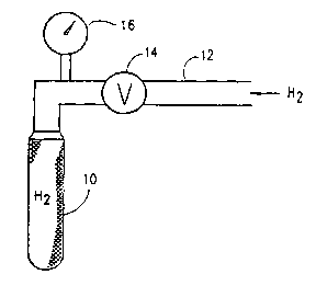
3 Reference is now made to Fig. 1, which is a
4 simplified illustration of apparatus for supplying atomic
hydrogen to a fluid. The apparatus preferably comprises a
6 porous ceramic tube 10, typically formed of alumina and
7 which is commercially available from Coors Ceramic Compa-
8 ny of Golden, Colorado, under catalog number AL 998-L3.
9 Molecular hydrogen from any suitable source, such as a
gas cylinder or an electrolysis device, is supplied to
11 the tube 10, via a conduit 12. A valve 14 and a pressure
12 indicator 16 may be provided along conduit 12.
13 The porous ceramic tube 10 is preferably
14 operative to prevent substantial diffusion of molecular
hydrogen therethrough, thereby retaining pressurized
16 molecular hydrogen therewithin over a relatively long
17 time, even when valve 14 is closed. Atomic hydrogen,
18 however, does become absorbed in pores of the tube 10,
19 communicating with the outer surface thereof.
By causing a fluid, such as a gas, e.g. air, or
21 a liquid, e.g. water or a hydrocarbon fuel, to flow past
22 tube 10, atomic hydrogen is supplied to the fluid, thus
23 reducing the redox potential thereof, i.e. increasing the
24 hydrogen activity of the fluid. Typical reductions of
redox potential may be from about +300mv to -lSOmv for
26 water, gasoline and air.
27 Reference is now made to Fig. 2 which shows the
28 apparatus of Fig. 1 in a bath 18 or conduit of a liquid.
29 The liquid is preferably stirred or otherwise caused to
flow past the tube 10, for reducing the redox potential
31 of the liquid in accordance with one embodiment of the
32 present invention.
33 Reference is now made to Figs. 3A and 3B, which
34 are simplified illustrations of apparatus for reducing
the redox potential of a gas in accordance with one
36 embodiment of the present invention. It is seen that a
E~ Sh~tl (R~LE 26~
Wo95/07857 ~ 81 PCT~S94/l0362
1 plurality of tubes 10 are associated via a manifold 20
2 with a source of molecular hydrogen. A fan 22, or any
3 other suitable device is provided for causing the gas to
4 flow past the tubes 10. It is appreciated that the water
vapor in the air picks up and reacts with the atomic
6 hydrogen. In effect, the redox potential of the gas is
7 thus reduced by reducing the redox potential of the
8 liquid carried thereby.
9 Reference is now made to Fig. 4A which is a
simplified illustration of apparatus for reducing the
11 redox potential of a liquid in accordance with another
12 embodiment of the present invention. A non-conductive
13 housing 30 is provided with a liquid inlet 32 and a
14 liquid outlet 34. A pair of respective negative and
positive electrolysis electrodes 36 and 38 are located
16 within the housing. By application of DC voltage across
17 the electrodes 36 and 38, hydrogen is caused to be
18 present on the negative electrode 36. This hydrogen is
19 picked up by the liquid passing through housing 30.
Oxygen and chlorine may be present on the positive elec-
21 trode 38. Generally, the oxygen does not oxidize water.
22 The chlorine strongly oxidizes the water by forming OH
23 radicals. The net result, however, is reduction of the
24 water.
Reference is now made to Fig. 4B which is a
26 simplified illustration of apparatus for reducing the
27 redox potential of a liquid in accordance with yet anoth-
28 er embodiment of the present invention. A housing 29 is
29 formed of stainless steel pipe and is associated with a
liquid inlet element 31 and a liquid outlet element 33.
31 The housing 29 is coupled to the negative terminal of a
32 DC power supply 35 and serves as a negative electrode.
33 Disposed preferably concentrically within
34 housing 29 is a stainless steel rod or pipe 37 which is
mounted by a pair of insulating mounts 39 and is coupled
36 to the positive terminal of power supply 35. Rod or pipe
lllt SIJEET (RULE 26)
WO 95/07857 ~ PCT/US94/10362 ~
~3~
14
1 37 serves as the positive electrode.
2 By application of DC voltage across the elec-
3 trodes 29 and 37, hydrogen is caused to be present on the
4 interior surface of housing 29. This hydrogen is picked
up by the liquid passing through housing 29. Oxygen and
6 chlorine may be present on the positive electrode 38.
7 Generally, the oxygen does not oxidize water. The chlo-
8 rine strongly oxidizes the water by forming OH radicals.
9 The net result, however, is reduced water.
Reference is now made to Fig. 5 which is a
11 simplified illustration of apparatus for reducing the
12 redox potential of a liquid in accordance with still
13 another embodiment of the present invention, wherein a
14 liquid is first oxidized and then reduced. The apparatus
comprises a pair of non-conducting housings 40 and 42
16 which are interconnected by a plurality of non-conducting
17 electrochemical bridges 44, each of which may include a
18 porous ceramic barrier 46. Each of housings 40 and 42
19 includes a liquid inlet and a liquid outlet, indicated
respectively by reference numerals 48, 50 and 52, 54. A
21 positive electrolysis electrode S6 is disposed within
22 housing 40, while a negative electrolysis electrode 58 is
23 disposed in housing 42.
24 The apparatus of Fig. S, which is particularly
suitable for disinfecting water, operates by causing
26 water to enter housing 40 via inlet 48 and to be oxidized
27 by electrode 56. The oxidized water, downstream of elec-
28 trode 56, is supplied to an oxidation enhancement cham-
29 ber 60, typically filled with activated carbon and ceram-
ic beads. Chamber 60 provides high surface contact and
31 dwelling time to enable the full oxidation of the water
32 by the oxygen and chlorine produced by the operation of
33 the positive electrode 56 on water, thereby to kill
34 microorganisms therein.
The thus disinfected water is then supplied
36 via inlet 52 to housing 42 wherein it is reduced. The
HEEr (RULE 26~
WO9S/07857 ~ ~ ~ PCT~S94/10362
1 reduced water from housing 42 is provided to a reduction
- 2 enhancement chamber 62, typically filled with activated
3 carbon and ceramic beads. Chamber 62 provides high sur-
4 face contact and dwelling time to enable the full reduc-
tion of the water.
6 Reference is now made to Fig. 6A which is a
7 simplified illustration of apparatus for reducing the
8 redox potential of a liquid, wherein a liquid is first
9 oxidized and then reduced in accordance with another
embodiment of the invention. Here a housing 70 is formed
11 of a conductor, such as stainless steel and defines a
12 negative electrolysis electrode. Housing 70 is formed
13 with a liquid inlet 72 and a liquid outlet 74. Disposed
14 within housing 70 is a tube 76 formed of a porous ceramic
material, which may be identical to that used in tube 10
16 described hereinabove.
17 A positive electrolysis electrode 78 is dis-
18 posed interiorly of tube 76, so as to oxidize liquid
19 entering through inlet 72. The oxidized liquid passes
along a conduit 80 to the interior of housing 70, outside
21 of tube 76, where it is reduced by hydrogen formed on the
22 interior surface of housing 70, which operates as a
23 negative electrode. Reduced, disinfected liquid, such as
24 water is output at outlet 74. Alternatively, the ceramic
tube 76 may be replaced by a fabric hose or similar
26 device, which does not permit significant passage there-
27 through of liquid but does permit passage therethrough of
28 electrical current.
29 Reference is now made to Fig. 6B which is a
simplified illustration of a variation of the apparatus
31 of Fig. 6A for reducing the redox potential of a liquid,
32 wherein a liquid is first oxidized and then reduced in
33 accordance with another embodiment of the invention.
34 Here a housing 82 is formed of a conductor, such as
stainless steel, and defines a negative electrolysis
36 electrode. Housing 82 is formed with a liquid inlet 84
S~ UlE 26)
WO 95/078S7 ~ PCT/US94/10362
16
1 and a reduced cathodic liquid outlet 86. Disposed within
2 housing 82 is a tube 88 formed of a porous ceramic mate-
3 rial, which may be identical to that used in tube 10
4 described hereinabove. Tube 88 is formed with a liquid
inlet 89 and an anodic water outlet 90.
6 A positive electrolysis electrode 92 is dis-
7 posed interiorly of tube 88, so as to oxidize liquid
8 entering through inlet 89. The oxidized liquid passes out
9 through outlet 90. Liquid entering via inlet 84 is re-
duced by hydrogen formed on the interior surface of
11 housing 82, which operates as a negative electrode.
12 Reduced, cathodic liquid, such as water, is output at
13 outlet 86. Alternatively, the ceramic tube 88 may be
14 replaced by a fabric hose or similar device, which does
not permit significant passage therethrough of liquid but
16 does permit passage therethrough of electrical current.
17 Reference is now made to Fig. 7 which is a
18 simplified illustration of a growing enclosure 94 includ-
19 ing apparatus for reducing the redox potential of the
interior atmosphere 98 thereof in accordance with an
21 alternative embodiment of the present invention. It is
22 seen that reducing water is employed not only for water-
23 ing the plants 94, but also for spraying in the air, so
24 as to reduce the redox potential of the interior atmos-
phere of the growing enclosure.
26 Reference is now made to Fig. 8 which is a
27 simplified illustration of apparatus for characterizing
28 hydrogen. Hydrogen is supplied to a container 100 typi-
29 cally formed of a porous ceramic material, such as that
employed for tubes 10, described hereinabove. Alterna-
31 tively tubes 10 and/or container 100 may be made of metal
32 through which it can be shown that hydrogen diffuses.
33 Disposed within container 100 is preferably a finely
34 divided material, preferably an organic material or other
active material which is a hydrogen donor, whose charac-
36 teristics it is sought to obtain in atomic hydrogen.
SUB~ k SlZEEl (RUIE 26)
W095/07857 ~ ~ 81 PCT~S94/10362
1 Hydrogen supplied to container 100 is exchanged with the
2 hydrogen of the material contained in container 100 and
3 the exchanged atomic hydrogen of the material collects
4 on the outer surface of the container 100, so as to be
able to be picked up by fluid, such as gas, or air,
6 flowing therepast. The exchanged atomic hydrogen has
7 characteristics of the material from which it was re-
8 ceived, and thus, in effect contains information.
g Reference is now made to Fig. 9 which is a
simplified sectional illustration of a multi-electrode
11 water treatment facility constructed and operative in
12 accordance with one preferred embodiment of the present
13 invention. The water treatment facility comprises a
14 container 200, preferably formed of a non-electrically
conductive material or coated with such a material,
16 typically having a generally rectangular configuration
17 and defining two opposite ends 202 and 204.
18 Adjacent ends 202 and 204 there are preferably
19 formed an anode 206 and a cathode 208 respectively.
Anode 206 and cathode 208 are preferably formed of car-
21 bon, such as graphite. Alternatively the anode and cath-
22 ode may be formed of any other suitable electrically
23 conductive material, such as platinum or gold, which is
24 not soluble under electrolysis.
A battery or other source of DC voltage 210 is
26 connected across anode 206 and cathode 208 as illustrat-
27 ed.
28 In accordance with a preferred embodiment of
29 the present invention a plurality of auxiliary electrode
assemblies 212, preferably having a carbon surface facing
31 cathode 208 and a surface of a selected metal facing
32 anode 206, are provided in mutually spaced relationship
33 between anode 206 and cathode 208 in container 200, thus
34 dividing the container as illustrated.
In accordance with a preferred embodiment of
36 the present invention, the plurality of auxiliary elec-
SU~ HEEr (I~ULE 26?
W095l07857 ~ PCT~S94/10362
1 trode assemblies includes electrode assemblies 212 having
2 anode-facing surfaces of different metals, such as for
3 example, Magnesium, Copper, Silver and Iron. The selec-
4 tion of metals is preferably in accordance with desired
properties of such metals which it is intended to impart
6 to water in accordance with a preferred embodiment of the
7 present invention.
8 A supply of water, such as ordinary tap or well
9 water, or alternatively any water based liquid having
electrical conductivity is supplied to container 200 via
11 an inlet 220. The water initially passes through a pas-
12 sageway 222 between anode 206 and a magnesium anode-
13 facing electrode surface 224, functioning as a cathode.
14 Thereafter, the water passes via a conduit 226 to a
passageway 228 between a carbon cathode-facing electrode
16 surface 230, functioning as a anode and a copper anode-
17 facing electrode surface 232, functioning as a cathode.
18 Thereafter, the water passes via a conduit 234 to a
19 passageway 236 between a carbon cathode-facing electrode
surface 238, functioning as a anode and a silver anode-
21 facing electrode surface 240, functioning as a cathode.
22 Thereafter, the water passes via a conduit 242 to a
23 passageway 244 between a carbon cathode-facing electrode
24 surface 246, functioning as a anode, and an iron anode-
facing electrode surface 248, functioning as a cathode.
26 Thereafter, the water passes via a conduit 250 to a
27 passageway 2S2 between a carbon cathode-facing electrode
28 surface 254, functioning as a anode and cathode 208.
29 Water exits passageway 252 via an outlet 256.
In accordance with a preferred embodiment of
31 the present invention, as the water passes through the
32 treatment facility some of the hydrogen atoms in the
33 water become substituted by hydrogen atoms which origi-
34 nated on the various metal anode-facing surfaces. In
accordance with a preferred embodiment of the invention,
36 this substitution imparts to the water certain character-
S~ E SH~ (RULE 26)
WO 95/07857 1~8~ PCT/US9d,/10362
19
1 istics of the respective metals of such surfaces. It is a2 particular feature of the invention that the characteris-
3 tics of the various metals are imparted to the water
4 without requiring that any metal atoms or ions enter the
water or become dissolved therein.
6 It is appreciated that any suitable number of
7 auxiliary electrode assemblies may be employed. They may
8 be electrically floating or alternatively coupled to
9 battery 210 and may be formed with surfaces of any suit-
able metal.
11 Reference is now made to Fig. 10 which is a12 simplified sectional illustration of a multi-electrode
13 water treatment facility constructed and operative in
14 accordance with another preferred embodiment of the
present invention. The facility of Fig. 10 is operative
16 initially to oxidize and thereafter to reduce water
17 passing therethrough, as distinguished from the facility
18 of Fig. 9, which only produces a reduced water output.
19 The water treatment facility of Fig. 10 com-
prises a container 300, preferably formed of a non-elec-
21 trically conductive material or coated with such a mate-
22 rial, typically having a generally rectangular configura-
23 tion and defining two opposite ends 302 and 304.
24 Adjacent ends 302 and 304 there are preferably
2s formed an anode 306 and a cathode 308 respectively.
26 Anode 306 and cathode 308 are preferably formed of car-
27 bon, such as graphite. Alternatively the anode and cath-
28 ode may be formed of any other suitable electrically
29 conductive material, such as platinum or gold, which is
not soluble under electrolysis.
31 A battery or other source of DC voltage 310 is
32 connected across anode 306 and cathode 308 as illustrat-
33 ed.
34 In accordance with a preferred embodiment of
the present invention a plurality of auxiliary electrode
36 assemblies 312, preferably having a carbon surface facing
SUB~ ul~ SHE~ (R~I~E 26)
wosslo7857 PCT~S94/10362
&$3~
1 cathode 308 and a surface of a selected metal facing
2 anode 306, are provided in mutually spaced relationship
3 between anode 306 and cathode 308 in container 300, thus
4 dividing the container as illustrated.
Further in accordance with a preferred embodi-
6 ment of the present invention, each of the auxiliary
7 electrode assemblies 312 is separated from the electrode
8 or electrode assemblies adjacent thereto by a non-elec-
9 trically conductive membrane 315 which permits passage of
ions but does not generally permit passage of water. A
11 typical membrane which is suitable for this purpose is a
12 thin porous ceramic plate or a cloth, having openings
13 sufficiently small so as to greatly restrict the amount
14 of liquid passing therethrough.
In accordance with a preferred embodiment of
16 the present invention, the plurality of auxiliary elec-
17 trode assemblies includes electrode assemblies 312 having
18 anode-facing surfaces of different metals, such as for
19 example, Magnesium, Copper, Silver and Iron. The selec-
tion of metals is preferably in accordance with desired
21 properties of such metals which it is intended to impart
22 to water in accordance with a preferred embodiment of the
23 present invention.
24 A supply of water, such as ordinary tap or well
water, or alternatively any water based liquid having
26 electrical conductivity, is supplied to container 300 via
27 an inlet 320. The water initially passes through a pas-
28 sageway 322 between anode 306 and a membrane 31S. There-
29 after, the water passes through a conduit 324 to a
passageway 326 between a carbon cathode-facing electrode
31 surface 328, functioning as a anode and another membrane
32 315. Thereafter, the water passes through a conduit 330
33 to a passageway 332 between a carbon cathode-facing
34 electrode surface 334, functioning as a anode and yet
another membrane 315. Thereafter, the water passes
36 through a conduit 336 to a passageway 338 between a
Sll~llllll~ SHE~ (RUL~ 26)
W095107857 PCT~S94/10362
21
1 carbon cathode-facing electrode surface 340, functioning
2 as a anode, and still another membrane 315. Thereafter,
3 the water passes through a conduit 342 to a passageway
4 344 between a carbon cathode-facing electrode surface
5 346, functioning as a anode, and a further membrane 315.
6 At this point the water is oxidized and sterilized.
7 Following the above-described oxidation step,
8 the water passes through a reducing process, much like
9 that described hereinabove in connection with Fig. 9. The
water passes through a conduit 348 to a passageway 350
11 between the cathode 308 and the same further membrane
12 315, mentioned above. From passageway 350, the water
13 passes via a conduit 352 to a passageway 354 between a
14 membrane 315 and an iron anode-facing electrode surface
15 356, functioning as a cathode. On the opposite side of
16 the membrane there is present carbon cathode-facing
17 electrode surface 340, functioning as an anode.
18 Thereafter, the water passes via a conduit 358
19 to a passageway 360 between a membrane 315, on the oppo-
20 site side of which there is disposed carbon cathode-
21 facing electrode surface 334 functioning as a anode, and
22 a silver anode-facing electrode surface 362, functioning
23 as a cathode. Thereafter, the water passes via a conduit
24 364 to a passageway 366 between a membrane 315, on the
25 opposite side of which there is disposed a carbon cath-
26 ode-facing electrode surface 328 functioning as a anode,
27 and a copper anode-facing electrode surface 368, func-
28 tioning as a cathode.
29 Thereafter, the water passes via a conduit 370
30 to a passageway 372 between a membrane 315, on the oppo-
31 site side of which is disposed anode 306, and a magnesi-
32 um anode-facing electrode surface 374, functioning as a
33 cathode. From passageway 372, the oxidized and subse-
34 quently reduced water passes to an outlet 378 and into
35 conduit 380.
36 As in the embodiment of Fig. 9, as the water
Sll~ u~ SHt~ ILE 26)
WO 95/07857 ~ PCT/US94/10362
1 passes through the reducing path of the treatment facili-
2 ty some of the hydrogen atoms in the water become substi-
3 tuted by hydrogen atoms which originated on the various
4 metal anode-facing surfaces. In accordance with a pre-
ferred embodiment of the invention, this substitution
6 imparts to the water certain characteristics of the
7 respective metals of such surfaces. It is a particular
8 feature of the invention that the characteristics of the
9 various metals are imparted to the water without requir-
ing that any metal atoms or ions enter the water or11 become dissolved therein.
12 Reference is now made to Fig. 11 which is a
13 simplified sectional illustration of a multi-electrode
14 water treatment facility constructed and operative in
accordance with a further preferred embodiment of the
16 present invention. The facility of Fig. 11 is operative
17 simultaneously to oxidize and to reduce water passing
18 therethrough in parallel streams.
19 The water treatment facility of Fig. 11 is
similar to that of Fig. 10 in that it comprises a con-
21 tainer 400, preferably formed of a non-electrically
22 conductive material or coated with such a material,
23 typically having a generally rectangular configuration
24 and defining two opposite ends 402 and 404.
Adjacent ends 402 and 404 there are preferably
26 formed an anode 406 and a cathode 408 respectively.
27 Anode 406 and cathode 408 are preferably formed of car-
28 bon, such as graphite. Alternatively the anode and cath-
29 ode may be formed of any other suitable electrically
conductive material, such as platinum or gold, which is
31 not soluble under electrolysis.
32 A battery or other source of DC voltage 410 is
33 connected across anode 406 and cathode 408 as illustrat-
34 ed.
In accordance with a preferred embodiment of
36 the present invention a plurality of auxiliary electrode
NEEI ~RUI~ 26~
~ W095/07857 pcT~ss4llo362
~l7~
1 assemblies 412, preferably having a carbon surface facing
2 cathode 408 and a surface of a selected metal facing
3 anode 406, are provided in mutually spaced relationship
4 between anode 406 and cathode 408 in container 400, thus
dividing the container as illustrated.
6 Further in accordance with a preferred embodi-
7 ment of the present invention, each of the auxiliary
8 electrode assemblies 412 is separated from the electrode
9 or electrode assemblies adjacent thereto by a non-elec-
trically conductive membrane 415 which permits passage of
11 ions but does not generally permit passage of water. A
12 typical membrane which is suitable for this purpose is a
13 thin porous ceramic plate or a cloth, having openings
14 sufficiently small so as to greatly restrict the amount
of liquid passing therethrough.
16 In accordance with a preferred embodiment of
17 the present invention, the plurality of auxiliary elec-
18 trode assemblies includes electrode assemblies 412 having
19 anode-facing surfaces of different metals, such as for
example, Magnesium, Copper, Silver and Iron. The selec-
21 tion of metals is preferably in accordance with desired
22 properties of such metals which it is intended to impart
23 to water in accordance with a preferred embodiment of the
24 present invention.
A supply of water, such as ordinary tap or well
26 water, or alternatively any water based liquid having
27 electrical conductivity, is supplied to container 400 via
28 a bifurcating inlet 420. One branch 421 of the inlet
29 directs part of the water initially through a passageway
422 between anode 406 and a membrane 415. Thereafter, the
31 water passes through a conduit 424 to a passageway 426
32 between a carbon cathode-facing electrode surface 428,
33 functioning as a anode, and another membrane 415.
34 Thereafter, the water passes through a conduit
430 to a passageway 432 between a carbon cathode-facing
36 electrode surface 434, functioning as a anode, and yet
S~S~ rE Sl~ttl (RUlE 26)
WO 95/07857 PCT/IJS9~110362
24
1 another membrane 415. Thereafter, the water passes
2 through a conduit 436 to a passageway 438 between a
3 carbon cathode-facing electrode surface 440, functioning
4 as a anode, and still another membrane 415. Thereafter,
the water passes through a conduit 442 to a passageway
6 444 between a carbon cathode-facing electrode surface
7 446, functioning as a anode, and a further membrane 415.
8 At this point the water is oxidized and sterilized and
g is supplied at an outlet 448 and into conduit 447.
A second branch 449 of inlet 420 leads another
11 part of the water through a reducing process, much like
12 that described hereinabove in connection with Fig. 9. The
13 water passes through a passageway 450 between a membrane
14 415 and a copper anode-facing electrode surface 456,
functioning as a cathode. On the opposite side of the
16 membrane is disposed anode 406.
17 Thereafter, the water passes via a conduit 458
18 to a passageway 460 between a membrane 415, on the oppo-
19 site side of which there is disposed carbon cathode-
facing electrode surface 428 functioning as an anode, and
21 a magnesium anode-facing electrode surface 462, function-
22 ing as a cathode. Thereafter, the water passes via a
23 conduit 464 to a passageway 466 between a membrane 415,
24 on the opposite side of which there is disposed carbon
cathode-facing electrode surface 434 functioning as a
26 anode, and an iron anode-facing electrode surface 468,
27 functioning as a cathode.
28 Thereafter, the water passes via a conduit 470
29 to a passageway 472 between a membrane 415, on the oppo-
site side of which is disposed carbon cathode-facing
31 electrode surface 440 functioning as a anode, and a
32 silver anode-facing electrode surface 474, functioning as
33 a cathode.
34 Thereafter, the water passes via a conduit 476
to a passageway 478 between a membrane 415, on the oppo-
36 site side of which is disposed carbon cathode-facing
SUR.~TITUT~ EF~UL~
WO95/07857 ~ PCT/US94/10362
~1
1 electrode surface 446 functioning as a anode, and cath-
2 ode 408. From passageway 478 the reduced water passes to
3 an outlet 480 and into conduit 482.
4 As in the embodiment of Fig. 9, as the water
passes through the reducing path of the treatment facili-
6 ty some of the hydrogen atoms in the water become substi-
7 tuted by hydrogen atoms which originated on the various
8 metal anode-facing surfaces. In accordance with a pre-
9 ferred embodiment of the invention, this substitution
imparts to the water certain characteristics of the
11 respective metals of such surfaces. It is a particular
12 feature of the invention that the characteristics of the
13 various metals are imparted to the water without requir-
14 ing that any metal atoms or ions enter the water or
become dissolved therein.
16 Reference is now made to Fig. 12 which illus-
17 trates a water treatment facility constructed and opera-
18 tive in accordance with yet another preferred embodiment
19 of the present invention. The facility comprises a con-
tainer 500 which is divided into two chambers 502 and 504
21 by a hydrogen permeable, otherwise non-permeable barrier
22 506, which functions as a cathode. Barrier 506 may com-
23 prise a metal plate or a barrier of any suitable sub-
24 stance, such as an alloy, which contains metal and other
elements.It is appreciated by applicant that hydrogen
26 permeates through metal, which is not otherwise perme-
27 able.
28 An anode 508 is disposed adjacent one wall of
29 the container 500 opposite cathode 506 at an opposite
side therefrom in chamber 502 and is electrically coupled
31 to the cathode by via a battery or other voltage source
32 510. Chamber 504 is provided with a water inlet 512 and a
33 water outlet 514 for circulation of water therethrough.
34 In accordance with a preferred embodiment of
the present invention, an electrolyte fills chamber 502
36 and hydrogen having the characteristics of the elements
S~EE~ ILE 26)
WO9S/07857 ~ PCT~S9~110362
26
1 making up the electrolyte and/or of the metal forming
2 the cathode 506 diffuses through the metal barrier 506
3 to the face thereof which is in -ontact with water flow-
4 ing through chamber 504. The hydrogen atoms appearing on
that face of the barrier 506 are exchanged with hydrogen
6 atoms making up the water and thus enter the water and
7 cause the water to have those characteristics.
8 The transfer of hydrogen having the character-
9 istics of the elements making up the electrolyte and/or
of the metal forming the cathode 506 to the water may be
11 enhanced by first oxidizing the water prior to supplying
12 it to chamber 504, such as by using the facility of Fig.
13 11.
14 It is appreciated that the facility described
above is operative to introduce hydrogen of desired
16 characteristics into any suitable water based solution as
17 well as to distilled water having substantially no impu-
18 rities.
19 A number of examples of the invention will now
be described:
21
22
23 EXAMPLE I - STRESS TOMAT0 PLANTS
24 Two sets of four trays of tomato plants were
grown in a greenhouse in Patterson, California. The
26 control tray was irrigated with well water whose measured
27 redox potential was between 270 and 300 mv, while the
28 test tray was irrigated with the same well water which
29 had been treated using reducing e~uipment of the type
illustrated in Fig. 4B. The measured redox potential of
31 the test irrigation water was about 50 mv.
32 Both trays were not irrigated for three days.
33 The lack of irrigation resulted in dehydration and brown-
34 ing of the plants in the control tray but did not result
in browning or visible stress in the test plants.
36
Sh~tl (RUlE26)
~ W095/07857 ~17~1 PCT~S94/10362
1 EXAMPLE II - STRESSED CAULIFLOWER PLANTS
2 Eight trays of cauliflower plants were grown in
3 a greenhouse in Patterson, California. The control trays
4 were irrigated with well water whose measured redox
potential was between 270 and 300 mv, while the test
6 trays were irrigated with the same well water which had
7 been treated using reducing equipment of the type illus-
8 trated in Fig. 4B. The measured redox potential of the
9 test irrigation water was about 50 mv. Both groups of
trays grew normally for about three months and appeared
11 to be identical.
12 Both sets of trays were not irrigated for three
13 days. The lack of irrigation resulted in dehydration and
14 browning of the plants in both the control trays and the
test trays. Irrigation was then resumed as before. Most
16 of the plants in the test trays returned nearly to their
17 previous normal state, but none of the plants in the
18 control trays revived.
19
EXAMPLE III - HIGH SALINITY STRESS CELERY PLANTS
21 Two identical beds of celery plants, each about
22 100 feet long and 12 feet wide and containing hundreds of
23 thousands of plants, were grown in a greenhouse in Sali-
24 nas, California. The control plants were irrigated with
well water whose measured redox potential was between 270
26 and 300 mv, while the test plants were irrigated with the
27 same well water which had been treated using reducing
28 equipment of the type illustrated in Fig. 4B. The meas-
29 ured redox potential of the test irrigation water was
about 50 mv.
31 Both groups of plants grew normally for about 6
32 weeks until salinity stress was noticed in the control
33 plants. The salinity stress was expressed in yellowing of
34 the control plants and damage to the roots of the control
plants. No corresponding salinity stress was noticed in
36 the test plants.
SU~ S~t (~UL~26~
WO 95/07857 PCT/US9 /10362
28
2 EXAMPLE IV - GROWTH AND VITALITY CAULIFLOWER PLANTS
3 Four trays of cauliflower plants were grown
4 outdoors in Patterson, California. The control trays were
irrigated with well water whose measured redox potential
6 was between 270 and 300 mv, while the test trays were
7 irrigated with the same well water which had been treated
8 by boiling for two minutes and subsequent cooling to
9 ambient temperature. The measured redox potential of the
test irrigation water was about 100 mv. Both groups of
11 trays grew normally for about one month and appeared to
12 be identical.
13 Thereafter the control plants began to show
14 signs of fatigue, loss of color, and susceptibility to
attack by pests. The test plants did not show such fa-
16 tigue or loss of color and showed less susceptibility to
17 attack by pests.
18
19 EXAMPLE V - GROWTH AND VITALITY TOMATO PLANTS
Forty acres of tomato plants were grown in Five
21 Points, California. Thirty-nine of the forty acres were
22 irrigated with water whose measured redox potential was
23 about 310 mv, while a control acre was irrigated with the
24 same water which had been treated using reducing equip-
ment of the type illustrated in Fig. 4B. The measured
26 redox potential of the test irrigation water was about 45
27 mv. All plants were seeded in January, 1993. Irrigation
28 began in April and proceeded for 8 hours once a week.
29 Plants were harvested on July 16, 1993.
Samples of fruit bearing plants were selected
31 from both the control and the test acreage during har-
32 vest. The test plants were larger and heavier than the
33 control plants. Although the number of tomatoes per plant
34 was about the same for the control and test plants, the
weight of the tomatoes in the test group was about 40%
36 higher than that for the control group. The solid con-
SVBSmUTE SNE~ (RULE 26)
W095/07857 ~ ~ PCT~S9~110362
1 tent, pH and other quality parameters were the same in2 both groups.
4 EXAMPLE VI - REDUCTION OF WATER BY ELECTROLYSIS
Well water at Patterson, California, having a
6 redox potential of 312 mv was supplied to apparatus of
7 the type illustrated in Fig. 4B at a rate of about 5
8 gallons per minute. The current was 20 Ampere and the
9 voltage was 16 Volts. The water output had a measured
redox potential of 45 mv. This water was supplied to a
11 spa and was circulated therethrough and was also employed
12 for irrigation.
13
14 EXAMPLE VII - REDUCTION OF WATER BY ELECTROLYSIS
Well water at Patterson, California, having a
16 redox potential of 312 mv was supplied to apparatus of
17 the type illustrated in Fig. 4B at a rate of about 5
18 gallons per minute. AC current was employed at 220 Volt.
19 The water output had a measured redox potential of 45 mv.
Operation of the apparatus of Fig. 4B using AC current
21 provided heating of the water and disinfection thereof in
22 addition to the reduction of the redox potential thereof.
23 This water was supplied to a spa and was circulated
24 therethrough and through the apparatus of Fig. 4B.
26 EXAMPLE VIII - REDUCTION OF WATER BY ELECTROLYSIS
27 Well water at Patterson, California, having a
28 redox potential of 270 mv was supplied to apparatus of
29 the type illustrated in Fig. 6A at a rate of about
gallon per minute. DC current was employed at 2 Amperes
31 and a titanium electrode 78 was employed.
32 The water output had a measured redox potential
33 of -50 mv.
34
EXAMPLE IX - REDUCTION OF WATER BY ELECTROLYSIS
36 Well water at Patterson, California, having a
SUB~ ~ SHEET (RULE 28)
WO 95/07857 ~ PCT/~JS94/10362
1 redox potential of 270 mv was supplied to apparatus of
2 the type illustrated in Fig. 6B at a rate of about
3 gallon per minute. DC current was employed at 2 Amperes
4 and a titanium electrode 92 was employed.
The water output at outlet 86 had a measured
6 redox potential of 350 mv. The water output at outlet 90
7 had a measured redox potential of -460 mv.
9 EXAMPLE X - DECHLORINATION AND REDUCTION OF WATER BY
ELECTROLYSIS
11 Well water at Patterson, California, having a
12 redox potential of 270 mv was chlorinated with commercial
13 chlorine solution. The redox potential of the chlorinated
14 water was 690 mv. The chlorinated water was supplied to
apparatus of the type illustrated in Fig. 6A at a rate of
16 about 1 gallon per minute. DC current was employed at 2
17 Amperes and a titanium electrode 78 was employed.
18 The water output had a measured redox potential
19 of 640 mv. This output was passed through an 8 inch long
tube containing active carbon. The water output from the
21 tube had a measured redox potential of -50 mv.
22
23 EXAMPLE XI - ICE CUBES OF REDUCING WATER
24 Hydrogen gas was bubbled into tap water using a
2S sparger for about one minute. The measured redox poten-
26 tial of the tap water was reduced thereby from 295 mv to
27 - 50 mv. The thus reduced water was frozen into ice cubes
28 and used subsequently in a variety of drinks. Melting of
29 the ice cubes greatly reduced the redox potential of the
drinks.
31
32 EXAMPLE XII - REDUCING WATER USING CERAMIC TUBE
33 Hydrogen was supplied under a pressure of 30
34 psi to a ceramic tube as illustrated in Fig. 2. Water was
provided at a redox potential of 285 mv. Upon agitating
36 the ceramic tube in the water, the redox potential of the
~IBSmU~E SHEEI ~RUlE 26)
W095/07857 ~ PCT~S94110362
1 water dropped to 8S mv.
3 EXAMPLE XIII - TRANSFER OF CHARACTERISTICS OF HYDROGEN
4 One gram of dry black pepper powder is placed
in a ceramic tube as illustrated in Fig. 2. Hydrogen gas
6 was supplied to the interior of the tube at a pressure of
7 25 psi. The water outside of the ceramic tube became
8 slightly discolored and had a slight taste of pepper.
9 Part of the ceramic tube was left above the
water line. Brown colored liquid droplets having a strong
11 taste of pepper were found on the outer surface of the
12 ceramic tube above the water line.
13 A control experiment identical to the foregoing
14 but using nitrogen gas instead of hydrogen gas, produced
none of the observed results.
16
17 EXAMPLE XIV - ENHANCEMENT OF HYDROCARBON FUEL
18 Hydrogen was sparged into regular unleaded
19 gasoline. The redox potential of the gasoline was reduced
from about 300 mv to - 150 mv. This gasoline was employed
21 in a lawnmower and an automobile and appeared to provide
22 easier starting and more powerful operation.
23
24 EXAMPLE XV - IRRIGATION OF TOMATO PLANTS
One control row of tomatoes was irrigated with
26 well water. Three additional rows were irrigated with
27 well water after the prices of reduction. The reducing
28 process was performed by two different treatment devices.
29 One device was constructed from a steel tube, serving as
a cathode; the cathode of the second device was made of
31 stainless steel. The row irrigated by the reduced water
32 flowing over the steel cathode exhibited faster growth
33 than the control row. The plants irrigated by water
34 reduced over a stainless steel cathode exhibited very
poor growth as compared to the control row.
36 Thus, it may be concluded that not only the
~UB~mUrE S~ET (RU~E 26)
WO 95/07857 PCT/US94110362
2)~
32
1 reduction enhances the growth but that the characteris-
2 tics of the hydrogen may have a positive or a negative
3 effect on the growth.
4 Experiments to study fungicidal, pesticidal and
herbicidal effects of water composed of hydrogen of
6 different specificity and characteristics are being
7 undertaken. These experiments were initiated in view of
8 the fact that proven materials contain specific elements.
EXAMPLE XVI - EXAMPLES OF USE OF APPARATUS OF FIGS. 9
11 AND 10
12 Water was reduced electrochemically in a rec-
13 tangular container having an anode and cathode spaced 15
14 cm apart. The voltage was 30 volts and the current was
0.2 amps. Both electrodes were made of steel. Hydrogen
16 evolved from the cathode and the iron electrode dissolved
17 on the anode. Placing a flat steel sheet of the same
18 dimensions as of the electrodes in the middle of the
19 container did not effect the current and the voltage. The
steel sheet was releasing hydrogen on the side facing the
21 anode and iron dissolution was observed on the side
22 facing the cathode. The amount of hydrogen on the cathode
23 and electrically floating sheet appeared to be the same.
24 The reduction of the water was enhanced. Placing four
sheets of steel in the water between the anode and the
26 cathode caused hydrogen evolution to appear on all the
27 sheets to the same degree as that on the sides facing the
28 anode. The water was reduced in a much shorter time than
29 that in previous experiment with the single steel plate.
The amount of iron dissolution increased correspondingly.
31 It was therefore concluded that the device in
32 Fig. 9 will reduce the water at a very fast rate and at
33 low power demands. Additionally, using different metals
34 for cathodes, hydrogen of multiple characteristics will
be formed in the water.
36 In order to oxidize the water for the purposes
Sl~tilu~ SNE~ (RUL~ 26)
O95/07857 `~ ~ t ~1 PCT~S94/10362
1 of sterilization, the anode passageway was separated from
2 the cathode passageway, as illustrated in Fig. 11. The
3 oxidization, as expressed in the redox potential, of the
4 water after passing through the anode passageways was
very efficient in comparison to the results obtained in
6 the device illustrated in Fig. 5.
8 EXAMPLE XVII - EXAMPLES OF THE USE OF APPARATUS OF
9 FIG. 12
Using a steel cathode and sulfuric acid as the
11 electrolyte, the steel blistered after a few hours. Using
12 hydrochloric acid, under the same conditions, did not
13 lead to blistering of the steel. Thus, it was concluded
14 that the composition of the electrolyte has an effect on
hydrogen permeability through the metal. It appears that
16 the similarity of the elements in the electrolyte and the
17 cathode has an effect on hydrogen permeability in the
18 metal. Experiments are now being conducted to study the
19 rate of reduction of the water in contact with the rear-
side of the cathode and the characteristics of the hydro-
21 gen in relation with the cathode material and the compo-
22 sition of the electrolyte.
23
24 EXAMPLE XVIII - EXAMPLE OF USE OF APPARATUS OF FIG. 8
A drop of perfume was placed in the porous
26 ceramic container which was filled with calcined carbon
27 granules. After evacuation of the air, the tube was
28 connected to a hydrogen gas cylinder and pressurized with
29 hydrogen gas to a pressure of approximately 2 atms. After
a few minutes an aroma of perfume was emanating from the
31 tube. The tube was placed in water. No gas sparging was
32 observed. The redox potential of the water was reduced.
33 After about 10 minutes the water had an aroma
34 of perfume. The water retained the aroma for more than
two weeks. The tube has been emanating the aroma for more
36 than a month at the same intensity. When the tube was
S~lBSTlT~i~ SHEFr (RIJEE 26)
WO 95/07857 PCT/US94/10362
2~
34
1 placed in either glycerin or alcohol no aroma of the
2 perfume was detected. This led to the conclusion that the
3 hydrogen loses its characteristic properties in these
4 non-aqueous liquids. These experiments also prove that
the molecules of the aroma material do not permeate
6 through the ceramic tube and that the aroma is sensed
7 through the characteristic hydrogen formed by the ex-
8 change process and permeating through the wall of the
9 tube.
11 EXAMPLE XIX - FURTHER EXAMPLE TO THE USE OF APPARATUS
12 OF FIG. 5
13 Three fish tanks containing well water were inhabit-
14 ed with small ornamental fish. One tank was maintained as
the control tank. The water in the second tank was circu-
16 lated through the anodic compartment of the device de-
17 scribed in Fig. 5. The initial redox potential was 230
18 mv. After circulating and oxidizing the water for a few
19 minutes the fish appeared to become sick; some were even
lying on their sides at the bottom of the tank. The redox
21 potential was measured to be 350 mv. When the potential
22 reached a value of about 500 mv some of the fish died.
23 Upon reduction of the water to a potential of about 100
24 mv the surviving fish resumed normal activity.
The redox potential of the water in the third
26 tank was reduced to value of -250 mv. The reduced poten-
27 tial appeared to have no effects on the activity of the
28 fish.
29
EXAMPLE XX - FURTHER EXAMPLE TO THE USE OF APPARATUS OF
31 ~IG. 5
32 Tap water at different redox potentials was
33 used for bread making. No additives such as the commonly
34 used, such as potassium bromate and gluten were added to
the dough. The control water at a redox potential of
36 about 500 mv did not yield satisfactory bread, in respect
SIJBSTIM~ ~HEET (RULE 26)
~ W095/07857 z PCT~S94/10362
~ 7~ 4~.~
1 to size, color and texture. The water oxidized to a
2 potential of about 600 mv yielded flat bread. Water
3 reduced to a redox potential of about 50 mv yielded a
4 bread of larger volume than normal (which was not commer-
cially acceptable) but also had no brown color and had
6 too large air cavities. After some experimentation, a
7 commercially acceptable bread was produced using water
8 with a redox potential of about 300 mv and without addi-
9 tives.
It will be appreciated by persons skilled in
11 the art that the present invention is not limited by what
12 has been particularly shown and described hereinabove.
13 Rather the scope of the present invention is defined only
14 by the claims which follow:
16
17
18
19
21
22
23
24
26
27
28
29
31
32
33
34
36
~BS~I~rrE SHEET (RULE 26~