Note: Descriptions are shown in the official language in which they were submitted.
A SHOWER HEAD ~ ~ 7 - 7
The present invention relates to a shower head comprising a
mouthpiece having a central, axial, throughgoing channel for
flow-through of water, whereby a rotationally symmetrical
deflector element for the water is situated in the vicinity of
the outer mouth of the channel, the mouthpiece being in
threaded connection with a support through which the water is
supplied and is adapted to be adjusted axially relatively to
the support, while the deflector element is carried by a stem
which with a radial clearance extends axially in the channel
and is fastened to the support.
For several years shower heads have been developed with a view
to low water consumption ("saving showers"), in the range of 6
to 10 1/min. This consumption is usually based on normal
water pressures, which are 3 to 5 kp/cm2. AS the consumption
is at a "saving level" already at such normal pressures, a
lower pressure will cause that the consumption will be lower
than desired at low pressures. The water consumption is
reduced to below the "limit of comfort" and causes negative
attitudes to such shower heads.
Shower heads able to cause pulsating spray have been known for
a long time. These are based on the use of a propeller-like
rotor inside the shower head. Such shower heads can usually
be converted between a normal condition for an even shower and
the pulsating shower.
Such shower heads are usually designed for a high water
consumption, and they are complicated.
In the development of shower heads for low water consumption
the aim has quite one-sided been to achieve the low
consumption, without taking into account the consequences with
respect to effect, comfort and the structure of the water
flowing out of the shower head. This has, on the one hand, in
most of the cases caused low water velocities and a less
favourable water structure and on the other hand designs which
may cause clogging due to impurities or lime in the water.
The present invention brings about a shower head which causes
a low water consumption at normal water pressure, which in a
less degree than known ~saving showers" reduces the water
7 5 2
consumption at low water pressure and which additionally can
be converted between a normal condition for showering and a
condition for pulsating showering ("massage showering"),
whereby the latter condition is achieved without any rotating
element in the shower head.
In accordance with the present invention, the deflector
element on the side facing the channel has a circumferential
groove having a curved cross section around the stem, and that
the region of the mouthpiece around the deflector element or
immediately axially inside thereof provides a conical surface
which extends converging outwardly and turns into a generally
cylindrical surface nearest to its free end.
When the mouthpiece has been screwed approximately to a
maximum into the support and the deflector element,
consequently, is approximately in its greatest distance from
the mouth of the channel, relatively large water drops having
a relatively large mutual distance and a large velocity are
formed, which leave the deflector element in a conical
surface. Some of the water hits the wall in the cavity, and
the water is reflected from the wall and leaves the mouthpiece
and forms a relatively homogeneous structure.
When the mouthpiece is screwed further from the support, so
that the deflector element is closer to the mouth of the
channel, an increased choking will take place at the deflector
element, but this position is well suited for low water
pressures, in that a relatively larger water consumption and a
comfortably feeling water velocity is achieved. When the
mouthpiece is screwed approximately to its terminal position
away from the support, and the deflector element,
consequently, is in a maximum proximity to the mouthpiece,
instability of the water will occur, and it will flow out in a
pulsating manner, i.e. that the drops will flow out in
"clusters".
That the surface surrounding the deflector element mainly is
conical and converges outwardly from the bottom surface in the
mouthpiece is of importance to the mode of flow past the
deflector element.
In an embodiment of the invention a feature has been developed
WO95/07760 2 1 7 ~ 7 5 2 PCT~094/00154
which has been found to be particularly advantageous, this
being that the stem is conical, at least in the portion
situated remote from the deflector element. That the stem is
conical has a direct influence on the cross section of the
water flow at the top of the channel. This cross section will
be at a min;mum when the mouthpiece has been screwed maximally
into the support. At the same time the deflector element is in
its maximum distance from the mouth of the channel. Hence, the
major part of the choking will take place at the top of the
channel. The effect of this is the above mentioned relatively
large drops of water. When, to the contrary, the mouthpiece
has been screwed maximally outwardly relatively to the
support, this cross section is at its maximum. At the same
time the deflector element is at its m;n;ml~m distance from the
channel. Hence, the major part of the choking will take place
at the deflector element. This permits an acceptable water
velocity and an acceptable water consumption also when the
supplied water is at low pressures.
The invention will in the following be further explained, by
means of an embodiment shown in the accompanying drawing.
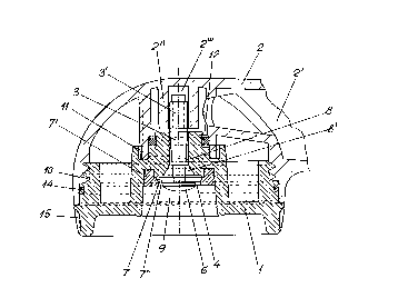
~ig. l shows a shower head in accordance with the
invention, in a section axially through the center
of the mouthpiece.
The scale of Fig. l is approximately 2 : l.
Fig. 2 shows in a larger scale (approx. 4 : l) the
deflector element contained in the shower head.
The section shown in Fig. l also intersects a channel 2' for
supply of water in the support 2, of which only a portion near
the shower head is shown. It will be appreciated that the
support in a known manner can be shaped as a handle or be
equipped with means for being fastened to a wall stand,
possibly as a combination of a handle and fastening device.
The shower head comprises a mouthpiece l, which by means of
W095/07760 2 1 7 1 7 5 2 PCT~094/0015~
threads 10 has been screwed into a support 2. The threads are
also used to adjust the axial position of the mouthpiece 1
relatively to the support 2. A stop 11 may be provided in
order to limit the possibility of such adjustment. Fig. 1
shows ribs 15 on the mouthpiece 1, distributed around its
circumference, in order to permit a good grip for screwing the
mouthpiece 1 relatively to the support 2. Fig. 1 also shows a
gasket ring 14 near the threads 10, but this ring is of little
importance and can be omitted.
The support 2 contains a channel 2' for supply of water.
The mouthpiece 1 has an inner cavity 9 which is open for
discharge of water and which is approximately cylindrical at
the bottom. Through an axial channel 8 the cavity 9
communicates with the inner channel 2' in the support 2.
A conical surface 7 has in the example shown been formed on a
ring 7' inserted in the cavity 9. The ring 7', which may be
made of plastics, can be fastened in an interference fit, but
is is also possible to fasten the ring by welding, for
instance by ultrasonic welding, when also the mouthpiece 1 is
made of plastics. The ring 7' may also be screwed into
threads. The surface 7 may be formed by the mouthpiece 1
itself, but due to the direction of taper of the surface 7 it
is consider to be simpler from reasons of manufacture that the
surface 7 is situated on a separate ring. Thereby the
mouthpiece 1 can be cast by use of a directly removable core.
The support 2 contains a boss 2'' having a threaded bore 2''',
and into the bore 2''' has been screwed one end 3' of a stem
3, the end 3' having threads 3''. On its distal end, in the
cavity 9, the stem 3 carries an approximately disc-shaped
deflector element 6, which on the side facing the channel 8
has been shaped with a circumferential groove 6' around the
end of the stem 3. The groove 6' is shown by a dotted line in
Fig. 2. Between the periphery of the deflector element 6 and
the conical surface 7 is an annular gap 4, which is altered by
screwing the mouthpiece 1 axially relatively to the support 2.
The stem 3 has a smaller diameter than the channel 8, so that
water can flow in an annular space between the stem 3 and the
wall of the channel 8. The end of the channel 8 facing the
deflector element 6 can be conically diverging. The axially
outermost surface 6'' on the deflector element 6 is shown
having the shape of a dome, but this surface is not considered
to have any substantial influence on the flow of water.
Together with the deflector element 6 the surface 7 forms an
annular chamber 7~, whose shape and size is altered when the
mouthpiece 1 is screwed axially relatively to the support 2,
and the chamber 7'~ influences the water in different ways,
depending on its shape and size.
The conical surface 7 does not need to be conical along its
entire length. The surface 7 may be cylindrical or
approximately cylindrical farthest out, towards the cavity 9.
The channel 8 may be mainly cylindrical, but in the vicinity
of the chamber 7'' the channel 8 may have a conical portion
8'.
A feature which has been found to be advantageous is that the
stem 3, at least in the region situated innermost in the
channel 8 (nearest to the boss 2''), is conical or otherwise
has a varying cross section, in such a manner that the cross
section is largest towards the fixed end 3' of the stem 3.
Presupposed that the channel 8 has a constant cross section in
this region it is achieved that the flow-through cross section
of the water innermost in the channel 8 is altered when the
mouthpiece 1 is screwed axially relatively to the support 2.
When the mouthpiece 1 has been screwed approximately maximally
into the support and the deflector element 6, consequently, is
approximately in its largest distance from the outer mouth of
the channel 8, relatively large drops of water having a
WO95/07760 2 ~ 7 1 7~ PCT~094/0015~
relatively large mutual distance and a large velocity are
formed, and leave the deflector element 6 in a conical
surface. Some of the water hits the wall in the cavity 9, and
the water is reflected from the wall and leaves the mouthpiece
1 and forms a rather homogeneous structure.
When the mouthpiece 1 has been screwed farther out relatively
to the support 2, whereby the deflector element 6 is closer to
the mouth of the channel, an increased choking will occur in
the gap 4 at the deflector element 6. This position is well
suited for low water pressures, in that a relatively larger
water consumption and a comfortably feeling water velocity is
achieved.
When the mouthpiece 1 has been screwed approximatly to its end
position outwardly from the support 2, whereby the deflector
element 6, consequently, is in a maximum proximity to the
mouthpiece 1, unstability of the water will occur, and it will
flow out in a pulsating manner and give the feeling of
massage.
The fact that the surface 7 surrounding the deflector element
6 mainly is conical and converges outwardly from the bottom
surface of the mouthpiece 1 influences the mode of outflow of
the water past the deflector element 6.
A sealing ring 12, shown as an O-ring, is inserted in an
annular space between the support 2 and the mouthpiece 1. The
ring prevents pressure drops due to leakage and also prevents
ingress of water into the cavity shown between the support 2
and the mouthpiece 1 and the creation of unsanitary conditions
in that the water remains in the cavity for a long time.
The groove 6' shown in Fig. 2 has such a cross sectional shape
that the groove 6' is deepest nearest to the stem. This
constitutes a non-limiting example. The groove has a curved
cross section, but the shape may vary.
woss/o776o 2 1 7 1 7 5 2 PCT~094/00154
It will be appreciated that the respective components in the
shower head may consist of plastics or metall, except from the
0-ring 12 and the possible gasket ring 14, which may be made
of synthetic rubber or natural rubber. The support 2 and the
mouthpiece l may for instance be cast, but it is considered
most convenient that the stem 3 and the deflector element 6
are manufactured in one piece by mechanical processing, i.e.
mainly turning and cutting of threads.