Language selection

Search

Patent 2171890 Summary

Third-party information liability

Some of the information on this Web page has been provided by external sources. The Government of Canada is not responsible for the accuracy, reliability or currency of the information supplied by external sources. Users wishing to rely upon this information should consult directly with the source of the information. Content provided by external sources is not subject to official languages, privacy and accessibility requirements.

Claims and Abstract availability

Any discrepancies in the text and image of the Claims and Abstract are due to differing posting times. Text of the Claims and Abstract are posted:

  • At the time the application is open to public inspection;
  • At the time of issue of the patent (grant).
(12) Patent: (11) CA 2171890
(54) English Title: CENTRIFUGAL FORCE SEPARATOR
(54) French Title: SEPARATEUR CENTRIFUGE
Status: Term Expired - Post Grant Beyond Limit
Bibliographic Data
(51) International Patent Classification (IPC):
  • B07B 7/08 (2006.01)
  • F16D 21/04 (2006.01)
  • F16D 23/12 (2006.01)
  • F16D 27/00 (2006.01)
(72) Inventors :
  • BARTHELMESS, ULRICH (Germany)
(73) Owners :
  • OMYA GMBH
(71) Applicants :
  • OMYA GMBH (Germany)
(74) Agent: SMART & BIGGAR LP
(74) Associate agent:
(45) Issued: 2001-09-18
(22) Filed Date: 1996-03-15
(41) Open to Public Inspection: 1996-09-29
Examination requested: 1998-06-29
Availability of licence: N/A
Dedicated to the Public: N/A
(25) Language of filing: English

Patent Cooperation Treaty (PCT): No

(30) Application Priority Data:
Application No. Country/Territory Date
195 11 313.4-23 (Germany) 1995-03-28

Abstracts

English Abstract

The invention relates to a centrifugal force separator whose rotor shaft protrudes at at least one of the two axial ends through a chamber for the discharge of the fines and the air. Particularly, the invention relates to the problem, in a centrifugal force separator with bilateral aspiration of fines and air, of reducing the distance between the bearings of the rotor shaft, while at the same time achieving an optimum between the requirement for unhampered outlet of the fines and the separating air, on the one hand, and, on the other hand, the requirement of a short distance between the bearings and, therefore, a short, light rotor shaft. According to the invention, each outlet chamber 17,18 provides an extension 19,20 or boss reaching inward axially, in which a bearing 21,22, for the rotor shaft is contained.


French Abstract

L'invention porte sur un séparateur à force centrifuge dont l'arbre du rotor dépasse d'au moins une des deux extrémités axiales à travers une chambre de décharge des particules fines et de l'air. En particulier, l'invention a trait au problème, dans un séparateur centrifuge avec aspiration bilatérale de particules fines et d'air, de réduire la distance entre les roulements de l'arbre du rotor, tout en obtenant un équilibre optimal entre l'exigence d'une sortie sans entrave des particules fines et de l'air de séparation d'une part et, d'autre part, l'exigence d'une distance courte entre les roulements et, par conséquent, un arbre de rotor court et léger. Selon l'invention, chaque chambre de sortie 17,18 fournit une extension 19, 20 ou un bossage s'étendant axialement vers l'intérieur, dans lequel un roulement 21, 22, pour l'arbre du rotor est contenu.

Claims

Note: Claims are shown in the official language in which they were submitted.

THE EMBODIMENTS OF THE INVENTION FOR WHICH AN EXCLUSIVE
PROPERTY OR PRIVILEGE IS CLAIMED ARE DEFINED AS FOLLOWS:
1. A centrifugal force separator comprising a separator
rotor having a rotor shaft with at least two axial
extremities and a bearing at each axial extremity, a
substantially cylindrical housing having a tangential air
inlet extending over the entire length of the separator
rotor, wherein the rotor shaft extends outwardly at both
axial extremities through the center of a first fines
outlet chamber at one end of the rotor shaft and through
the center of a second fines outlet chamber at the other
end of the rotor shaft, said fines outlet chambers having
diameters which are substantially equal to the diameter of
the separator, and wherein both first and second fines air
outlet chambers have central bosses extending inwardly in
the axial direction, in which bearings for the rotor shaft
are inserted, and wherein the fines outlet chambers
surrounding the bearings widen helically or spirally
outwardly in the axial direction.
2. The centrifugal force separator according to claim 1,
further comprising radial arms provided on the rotor shaft
in regions of the two axial extremities, said regions being
located inwardly from the bearings at each axial extremity,
wherein the radial arms connect end rings of the rotor to
the rotor shaft and wherein the radial arms are inclined
inwardly from each axial extremity toward one another,
thereby reducing the distance between the radial arms and
allowing the two bearings to be located closer to each
other.
9

3. The centrifugal force separator according to claim 2,
further comprising a plurality of coarse grain collecting
and outlet chambers substantially wedge-shaped in side
view, provided adjacent to a lower end of the housing, each
chamber extending over a portion of the circumference of
the separator.
4. The centrifugal force separator according to claim 3,
further comprising an annular channel in each of the fines
outlet chambers, provided for delivering air to a seal
between the end ring and a housing wall opposite the end
ring.
5. The centrifugal force separator according to claim 4,
further comprising an underside of the annular channel for
the admission of the material to be separated, and having
a section or cutout which widens spirally in the direction
of flow, for the uniform distribution of the material over
the circumference of the separator.
10

Description

Note: Descriptions are shown in the official language in which they were submitted.


- ~~'~~.B~J
Centrifugal Force Separator
BACKGROUND OF THE INVENTION
The invention relates to a centrifugal force separator having
a substantially cylindrical housing with a tangential separating-
air inlet extending over the entire height of the separator rotor,
and whose rotor shaft extends outwardly at both axial ends through
an outlet for the fines and the air, the diameter of the outlet
being substantially equal to the diameter of the rotor.
A centrifugal force separator of this kind has previously been
disclosed in German Federal Patent 2,951,819. This separator is
characterized by a high throughput, together with a high output of
fines with little coarse material or wrong size material in the
fines .
It is a disadvantage, however, that this kind of construction
calls for a relatively long shaft, and thus a heavy one. The two
fines/air outlet chambers are formed each by an elbow-shaped piece
of pipe whose diameter corresponds approximately to that of the
rotor. The rotor shaft passes through these curved outlet pipe
sections, and it has to be sufficiently sealed against the pipe
from the ambient atmosphere. On both sides of the seals a bearing
for the shaft is provided. On the upper end of the shaft is a belt
pulley or the like.
1

CA 02171890 2001-06-21
The rotor shaft as well as the separator rotor must be of
compact and relatively massive construction due to the great
axial distance between the bearings, in order to achieve the
necessary strength and prevent vibration.
German Federal Patent 2,825,400 has already disclosed a
centrifugal force separator whose rotor buckets are fastened
at both ends to an end ring and the two end rings are mounted
at their outer circumference in a hydrostatic, aerostatic or
electromagnetic bearing. Such bearings, however, are rather
expensive, especially due to the large diameter of the end
rings.
SUMMARY OF THE INVENTION
The present invention is addressed to the problem, in a
centrifugal force separator of the kind described above, of
reducing the distance between the bearings of the rotor shaft,
although the bearings are to be accessible from the outside for
maintenance, measurement and repairs; at the same time, an
optimum is to be achieved between the requirement of an
unhampered fines and discharge air outlet, the short distance
between bearings, and accessibility.
As embodied and broadly described, the invention provides
a centrifugal force separator comprising a separator rotor
having a rotor shaft with at least two axial extremities and
a bearing at each axial extremity, a substantially cylindrical
housing having a tangential air inlet extending over the entire
length of the separator rotor, wherein the rotor shaft extends
outwardly at both axial extremities through the center of a
first fines outlet chamber at one end of the rotor shaft and
through the center of a second fines outlet chamber at the
other end of the rotor shaft. The fines outlet chambers have
2

CA 02171890 2001-06-21
diameters which are substantially equal to the diameter of the
separator, and both first and second fines air outlet chambers
have central bosses extending inwardly in the axial direction,
in which bearings for the rotor shaft are inserted, and wherein
the fines outlet chambers surrounding the bearings widen
helically or spirally outwardly in the axial direction.
The solution to the problem is that the inwardly reaching
extension of boss for containing the bearing takes up
relatively little space, so that the remaining cross section
suffices for the unhampered outlet of the fines and discharge
air.
2A

~17I890
At the point on the circumference where this outlet chamber,
expanding like a snail shell, reaches its greatest inside diameter,
i.e. after 360 degrees, or after one full turn from the start of
the snail-shell-like or helicoidal formation, there follows a
preferably tangential outlet conduit.
Aside from the aerodynamically efficient configuration of such
a snail-shell discharge chamber, the result is that the bearing
housed axially inwardly in the boss is easily accessible, or in any
case in the relatively large circumferential area of the beginning
or point of origin of the discharge shell or helix. Another result
is a low axial height.
Since the rotor shaft becomes lighter and thinner with the
shorter distance between the bearings, the space occupied by the
bearings becomes reduced accordingly. The forces produced become
lower in the same proportion, so that smaller cross sections or
wall thicknesses can be used accordingly.
The distance between the bearings of the rotor shaft can be
further reduced by causing the end rings with the radial arms
connected to the rotor shaft to be inclined inwardly toward one
another.
In particular, many different possibilities of configuration
result. The separator rotor can be disposed horizontally or
3

~1'~1890
vertically.
If the separator rotor is disposed horizontally, the amount of
the granules to be separated are most simply fed in together with
the air, so the granules are already relatively fine, so that the
coarser grains are also carried by the air stream. Underneath the
separator rotor there is provided a large, funnel-shaped outlet
chamber in which the air velocity drops sharply, so that the coarse
granules drop down into the outlet funnel.
For coarser granules a vertical arrangement of the separator
rotor would probably be more advisable. In this case, the mixture
being separated can be delivered as usual from above into the
separating chamber surrounding the rotor.
At the bottom end of the housing, a plurality of funnel-shaped
coarse material outlets extending each over part of the
circumference can lead into the separating chamber. Their bottom
surfaces can be provided with a hard, wear-resistant and at the
same time smooth coating, e.g., a ceramic glaze. The smoother the
surface is the less they need to slope, so that the axial height
can be lower.
BRIEF DESCRIPTION OF THE DRAWINGS
For further explanation of the invention, examples of its
embodiment will be described below.
4

X1'71890
Fig. 1 shows a longitudinal section through a vertically
disposed centrifugal force separator according to the
invention;
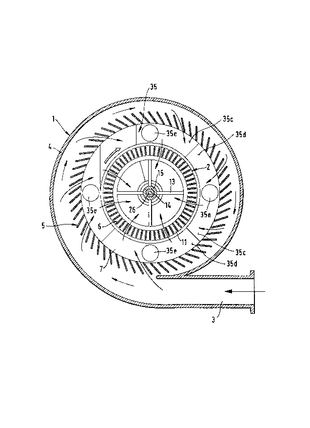
Figs. 2, 3 and 4 show cross sections taken along the lines II-II,
III-III, and IV-IV in Fig. 1;
Fig. 5 is a side view of the separator.
DETAILED DESCRIPTION OF THE INVENTION
The separator has a vertically disposed, substantially
cylindrical housing 1 in which a separator rotor 2 can rotate. The
separator rotor has a tangential air inlet 3 extending over the
entire height. At a radial distance from the housing case 4, an
entrance bucket wheel 5 is provided. Also at a radial distance
from the driving bucket wheel the fan or bucket wheel 6 of the
separator rotor is provided. The granules to be separated are fed
downwardly into the cylindrical ring separating chamber 7 extending
between the entrance bucket wheel and the fan wheel. Above the
separating chamber there is provided an annular channel for blowing
in the granular material, with an input connection 9. .
The separating fans 6 are held fast between an upper and lower
end ring 10 and 11; from the end rings extend substantially radial
arms 13 toward hubs 15 affixed to the shaft 14 of the rotor 2. To
stiffen the fan wheel 6 another, central ring l0a is provided,
which also is connected fixedly by radial arms 13a and a hub 15a to

_ ~ 171890
the rotor shaft 14.
At each end of the separator rotor 2 there is a chamber 17, 18
for the discharge of fines and the air. The gap between the end
rings 10 and li of the separator rotor 2 and the confronting
annular housing wall is sealed such that no coarse particles can
pass from separating chamber 7 into the fines chamber 17. For this
purpose, an annular channel 16 is provided which has connection
bores 16a distributed over the circumference.
According to the invention, both the upper and lower fines
outlet chamber 17 and 18 have central bosses 19 and 20, in which
bearings 21 and 22 for the rotor shaft 14 are inserted. The result
is a very short distance, in comparison to the state of the art,
between the two bearings 21 and 22 and hence a correspondingly
short and light rotor shaft.
The radial arms 13 between the end rings 10 and 11 and the
rotor shaft are inclined inwardly toward one another, so that the
two radial bearings 21 and 22 can be set still further inwardly,
that is, the rotor shaft becomes still shorter.
Each bearing 21 and 22 is sealed from the interior by an
annular gap seal 24 and 25, to which flushing air is fed through
axial and radial flushing air channels 26 in the shaft.
6

~1'~1890
To correspond to the tapered bearing case, a conical ring 27
is provided by which the flow is guided and an additional sealing
gap is formed.
The two fines outlet chambers 17 and 18 are of a helical or
spiral configuration formed by cylindrical outer walls 29,
cylindrical inner walls 30 and outwardly spiraling walls 31 that
are circular in plan between them. The rotor shaft bearings 21 and
22 are contained in the inner cylindrical walls 30 and the above-
mentioned bosses 19 and 20. In the circumferential area at which
the outlet spiral begins the bearings are especially easily
accessible from the side.
At the top, radially outwardly, the annular mixture inlet
passage 8 adjoins the outer cylindrical wall 29. In Fig. 2, the
connection 9 is inclined and tangential to the annular passage 8.
The underside of the annular passage is provided with a spiral-
shaped section 8a that widens in the direction of flow, so that the
material being separated is distributed uniformly over the
circumference.
Above the upper outlet chamber 17 there is a ring-shaped plate
33 or platform on which the motor or transmission is mounted. At.
the upper end of the boss, an axial bearing 34 is provided, which
bears the weight of the rotor.
7

With the drive arranged in this manner, the bearing 21 and the
seal 24 are still accessible through a lateral window 32 in the
boss 19; this window is provided below the platform 33 and above
the bearing 21.
On the opposite end, i.e., the bottom end of the casing, four
funnel-shaped coarse grain outlets 35 are provided, each extending
over one-fourth of the circumference, and between them the bottom
bearing 22 is easily accessible from the side.
Each of the four coarse grain outlets 35 thus consist of an
inner and an outer, outwardly bulging vertical wall 35a, 35b and a
radial wall 35c, 35d, each inclined toward an outlet connection
35e.
8

Representative Drawing
A single figure which represents the drawing illustrating the invention.
Administrative Status

2024-08-01:As part of the Next Generation Patents (NGP) transition, the Canadian Patents Database (CPD) now contains a more detailed Event History, which replicates the Event Log of our new back-office solution.

Please note that "Inactive:" events refers to events no longer in use in our new back-office solution.

For a clearer understanding of the status of the application/patent presented on this page, the site Disclaimer , as well as the definitions for Patent , Event History , Maintenance Fee  and Payment History  should be consulted.

Event History

Description Date
Inactive: Expired (new Act pat) 2016-03-15
Inactive: IPC from MCD 2006-03-12
Grant by Issuance 2001-09-18
Inactive: Cover page published 2001-09-17
Amendment After Allowance Requirements Determined Compliant 2001-07-05
Letter Sent 2001-07-05
Inactive: Adhoc Request Documented 2001-07-04
Letter Sent 2001-06-21
Amendment After Allowance Requirements Determined Compliant 2001-06-21
Inactive: Final fee received 2001-06-12
Amendment After Allowance (AAA) Received 2001-06-12
Inactive: Amendment after Allowance Fee Processed 2001-06-12
Pre-grant 2001-06-12
Inactive: Amendment after Allowance Fee Processed 2001-06-11
Amendment After Allowance (AAA) Received 2001-06-11
Notice of Allowance is Issued 2001-03-08
Letter Sent 2001-03-08
Inactive: Approved for allowance (AFA) 2001-02-22
Amendment Received - Voluntary Amendment 1999-02-09
Letter Sent 1998-07-22
Inactive: Application prosecuted on TS as of Log entry date 1998-07-21
Inactive: Status info is complete as of Log entry date 1998-07-21
Request for Examination Requirements Determined Compliant 1998-06-29
All Requirements for Examination Determined Compliant 1998-06-29
Application Published (Open to Public Inspection) 1996-09-29

Abandonment History

There is no abandonment history.

Maintenance Fee

The last payment was received on 2001-02-19

Note : If the full payment has not been received on or before the date indicated, a further fee may be required which may be one of the following

  • the reinstatement fee;
  • the late payment fee; or
  • additional fee to reverse deemed expiry.

Please refer to the CIPO Patent Fees web page to see all current fee amounts.

Owners on Record

Note: Records showing the ownership history in alphabetical order.

Current Owners on Record
OMYA GMBH
Past Owners on Record
ULRICH BARTHELMESS
Past Owners that do not appear in the "Owners on Record" listing will appear in other documentation within the application.
Documents

To view selected files, please enter reCAPTCHA code :


To view images, click a link in the Document Description column. To download the documents, select one or more checkboxes in the first column and then click the "Download Selected in PDF format (Zip Archive)" or the "Download Selected as Single PDF" button.

List of published and non-published patent-specific documents on the CPD .

If you have any difficulty accessing content, you can call the Client Service Centre at 1-866-997-1936 or send them an e-mail at CIPO Client Service Centre.


Document
Description 
Date
(yyyy-mm-dd) 
Number of pages   Size of Image (KB) 
Claims 1999-02-09 2 68
Cover Page 1996-06-20 1 16
Abstract 1996-06-20 1 22
Description 1996-06-20 8 247
Claims 1996-06-20 2 50
Drawings 1996-06-20 5 128
Description 2001-06-11 9 270
Description 2001-06-21 9 276
Cover Page 2001-09-06 1 45
Abstract 1998-08-20 1 22
Description 1998-08-20 8 242
Claims 1998-08-20 2 52
Representative drawing 1998-03-24 1 38
Reminder of maintenance fee due 1997-11-18 1 111
Acknowledgement of Request for Examination 1998-07-22 1 194
Commissioner's Notice - Application Found Allowable 2001-03-08 1 164
Correspondence 2001-06-21 2 54
Fees 2001-02-19 1 44
Correspondence 1996-04-03 14 437