Note: Descriptions are shown in the official language in which they were submitted.
CA 02171969 2005-03-03
- 1 -
TROCAR WITH REPLACEABLE OBTURATOR
Technical Field
The present invention is directed to trocars for
inserting an access tube or "cannula" through an abdominal
wall, and more particularly to a reusable trocar having an
easily replaceable obturator portion.
Backaround of the Invention
An increasing number of abdominal surgical
procedures are being performed with laparoscopic techniques in
order to avoid a large skin incision. Typically in
laparoscopic surgery, a special needle, similar to the
pneumoneedles described in U.S. Patent No. 4,808,168 to
Warring and U.S. Patent No. 5,374,252, is inserted through the
skin, and used to inflate the abdominal cavity with an
insufflating gas such as COz. Once the abdomen is adequately
dilated, the needle is removed and a rigid access tube or
cannula with a larger diameter (for example 10 or 11 mm) is
passed through the skin in the same location.
The access tube provides access for laparoscopes or
other laparoscopic surgical tools such as the stapler
described in U.S. Patent No. 5,040,715 or the surgical clip
appliers described in U.S. Patent Nos. 5,084,057 and
5,100,420. To drive the access tube through the skin, the
surgeon places a trocar obturator in the lumen of the access
tube to provide a sharp, leading edge for cutting tissue.
The art is replete with trocar devices such as those
shown in U.S. Patent Nos. 4,535,773, 4,601,710, 4,654,030,
4,902,280, and 4,931,042. A prior art trocar device typically
comprises a sharp point for permitting the skin, surrounded by
a
WO 95/07663 PCT/US94/08930
2171969
- 2 -
spring-loaded protective sleeve. As these trocar
devices are urged through the skin, friction with the
skin causes the protective sleeve to slide proximally
(rearwardly). After the access tube has penetrated
through the skin, there is no longer friction between
the protective sleeve and the skin, and the spring is
designed to urge the protective sleeve distally
(forwardly) to cover the sharp point, locking the
protective sleeve in position to reduce the risk of
accidental puncture of the underlying organs.
Two typical "safety" trocars currently
available are known as the "Auto Suture Surgiport" T.M.
(generally available from U.S. Surgical of Norwalk,
Connecticut) and the "Endopath" T.M. (generally
available from Ethicon of Somerville, N.J.). Trocars
similar, but not identical to these are shown in U.S.
Patents 5,066,288 and 5,030,206. These types of prior
art trocar devices are generally used during a surgical
procedure and then disposed of after the surgical
procedure is completed. Such prior art trocars tend to
be expensive and complicated, particularly when a
"safety" mechanism is included. Also, the presence of
a shield or protective sleeve necessarily reduces the
size of the obturator/knife used with a given size of
cannula and may cause other problems for the user or
patient.
A more cost effective alternative to a
disposable trocar is a completely reusable trocar, such
as the Trocars generally available from Snowden-Pencer,
Inc. of Tucker, Georgia or the Trocars generally
available from Solos, Endoscopy, Inc. of Duluth
Georgia. A reusable trocar typically comprises an
obturator assembly having sharp surfaces for cutting
tissue, and a cannula or access tube assembly.
The obturator assembly of a typical reusable
trocar may be used on a patient and then cleaned and
sterilized for reuse on the same or a different
WO 95/07663
PCT/US94/08930
- 3 -
patient. Reusable trocars tend to have minimal parts
to afford quick and convenient cleaning and
sterilization of the trocars.
Reusable trocars tend to encounter problems
as the sharp tissue cutting surfaces of the obturator
(including the tip) of a completely reusable trocar
tend to become dull after even a few uses. Such
dulling of the cutting surfaces of the trocar generally
tends to increase the insertion force required to
insert the trocar into the abdominal cavity.
Additionally, the sharp tissue cutting
surfaces of a reusable trocar are vulnerable to
mechanical damage from mishandling or other abuse
during cleaning, sterilization and handling. For
example, if the cutting surfaces or tip of a reusable
trocar impulsively impact a solid object (such as when
the obturator is inadvertently dropped on the floor or
working area), the tip of the obturator tends to take a
highly undesirable "hook" shape.
U.S. Patent No. 4,601,710 discloses a trocar
assembly having a trocar tip attached to the rest of
the trocar assembly by set screws or threads. Also,
AeSclepios Surgical Endoscopy, Inc. of Montreal, Quebec
Canada and General Medical of Richmond Virginia are
believed to currently sell a reusable trocar having a
trocar tip that is attached to the rest of the trocar
assembly by threads.
Threading the trocar tip to the rest of the
trocar assembly is believed to be undesirable because
it may be difficult for the user to determine when the
trocar tip is completely screwed into the rest of the
trocar assembly. Although some surgeons prefer that
the trocar tip slightly rotate relative to the cannula
during insertion, some surgeons prefer that the trocar
tip remain stationary relative to the cannula during
insertion. If the trocar is used when the trocar tip
is not completely screwed into the rest of the trocar
CA 02171969 2005-03-03
- 4 -
assembly, the trocar tip may rotate relative to the rest of
the trocar assembly and the cannula. Again, some surgeons
wish to avoid such action. Also, the threaded portion of such
a trocar is believed to be difficult to clean or sterilize as
in some procedures, it may expose a healthcare worker to
relatively sharp threaded surfaces that may be contaminated.
Using a set screw to attach the trocar tip to the
rest of the trocar assembly is believed to be cumbersome or
difficult for the user, as a user is required to manipulate a
potentially fine set screw.
Finally, the art is replete with various types of
designs for the distal ends of trocars used during
laparoscopic surgical procedures. Examples of distal ends of
trocars include pyramidal (with at least three cutting
surfaces), elliptical-shaped, blunt (known in the art as
Hasson-type obturators), and conical or frusto-conical shaped.
However, when a trocar with a particular distal end is
disposed of, both the proximal and distal end of the trocar
are disposed of resulting in unnecessary waste with attendant
cost disadvantages.
Summary of the Invention
According to an embodiment of the present invention
there is provided a kit assembly for use during a laparoscopic
surgical procedure comprising: a proximal portion of a trocar
having a handle adapted to be manually grasped, and attachment
means for releasably connecting said proximal portion of said
trocar to a distal portion, and a plurality of distal portions
comprising: a first distal portion having a means, cooperable
with said attachment means, for releasbly connecting said
first distal portion to said proximal portion, and a first
distal end portion, and a second distal portion having a
means, cooperable with said attachment means, for releasably
CA 02171969 2005-03-03
- 5 -
connecting said second distal portion to said proximal
portion, and a second distal end portion, and wherein said
second distal end portion is different than said first distal
end portion.
In accordance with another embodiment of the present
invention there is provided a kit assembly for use during a
laparoscopic surgical procedure, said kit assembly comprising:
a trocar assembly for placement in a cannula to facilitate
inserting the cannula through a wall having tissue defining a
body cavity, which cannula comprises interior surfaces
defining a lumen and a distal end having an opening, the
trocar assembly comprising: a handle; an obturator extending
from the handle and having an axis; the obturator comprising:
a proximal portion; a first distal end portion comprising a
base part and surfaces adapted to engage the wall defining the
body cavity; detent means for releasably connecting the
proximal portion of the obturator to the first distal end
portion of the obturator, the detent means having release
restricting means, cooperable with the cannula, for resisting
separation of the proximal and first distal end portions of
the obturator when the obturator is placed within the lumen of
the cannula; and a second distal end portion comprising
surfaces adapted to engage the wall defining the body cavity;
and wherein the second distal end portion is different than
the first distal end portion.
The invention also provides a method of using a
trocar assembly comprising the steps of: providing a cannula
comprising interior surfaces defining a lumen and a distal end
having an opening; providing a kit having the trocar assembly,
the kit comprising a handle, an obturator extending from the
handle, the obturator comprising a proximal portion, and a
first distal end portion comprising a surface adapted to
engage a wall defining a body cavity, and detent means for
CA 02171969 2005-03-03
- 5a -
releasably connecting said proximal portion of said obturator
to said first distal end portion of said obturator, and a
second distal end portion that is different than said first
distal end portion; attaching the first distal end portion to
the proximal portion; then placing the obturator within the
cannula; inserting the cannula through a wall having tissue
defining a body cavity; then removing the used or dull first
distal end portion; and replacing the used or dull first
distal end portion of the obturator with the second distal end
portion.
Each preferred embodiment of the reusable trocar
assembly (1) affords sharp cutting surfaces even after
repeated trocar uses, (2) has an obturator having a proximal
portion and a distal end portion with sharp surfaces for
CA 02171969 2005-03-03
5b
cutting tissue, (3) affords firm retention of the distal end
portion by the proximal portion while the obturator is
inserted and removed from the patient's body, but which also
affords easy convenient release of the distal end portion from
the proximal portion to afford replacement of the used or dull
distal end portion, (4) affords convenient and efficient
disposal and replacement of a used or dull obturator distal
end portion, (5) optionally includes a mechanism for releasing
the distal end portion without requiring a user to grasp the
distal end portion, (6) is inexpensive and easy to
manufacture, (7) affords convenient, rapid sterilization and
cleaning of its reusable portions, (8) which is convenient and
simple to use, (9) which may be provided in a kit assembly
that affords the use of a plurality of different types or
styles of distal end portions with the same proximal portion
with potential cost-savings and simplification of cleaning and
sterilization procedures.
The disclosed trocar assembly for placement in a
cannula facilitates inserting the cannula through a wall
having tissue defining a body cavity. The cannula comprises
interior surfaces defining a lumen and a distal end having an
opening. The trocar assembly comprises a handle, and an
obturator having an imaginary axis.
The obturator comprises a proximal portion, and a
distal end portion comprising a base part. This distal end
portion has cutting surfaces adapted to pierce the wall
defining the body cavity.
The trocar assembly also comprises detent means for
releasably connecting the proximal portion of the obturator to
CA 02171969 2005-03-03
5c
the distal end portion of the obturator. The detent means
comprises a groove part extending at least partially about the
axis of the obturator located on one of the proximal and
distal end portions and a detent part situated on the other of
the proximal and distal end portions and adapted to engage the
groove part.
When the obturator is placed within the cannula, at
least a portion of the groove part and the detent part are
situated within the lumen of the cannula and the cutting
surfaces project beyond the distal end of the cannula. In
this configuration the detent part is "locked" to the groove
part to restrict
PCT/US94/08930
WO 95/07663 2 ~ ~ ~ 9 6 9
- 6 -
the chances of the distal end portion of the obturator
falling into the patient.
Several species of trocar assemblies are
shown and described. The trocar assemblies have
various features. For example, a first embodiment of
trocar assembly comprises means for restricting
relative rotation between the distal end portion and
the proximal portion comprising leaf spring members and
ribs which mesh.
Both the first and a second embodiments of
trocar assembly describe different means for releasing
the distal end portion without requiring the user to
grasp the distal end portion. The first embodiment
describes an ejector rod having a distal end adapted to
abut a proximal end of the distal end portion, and a
button member mounted to the ejector rod and movable
between a release and a rest position.
The second embodiment of trocar assembly
describes a disposal container having first and second
sections each having manually engagable outer surfaces
and trocar distal end portion engaging surfaces. The
disposal container's first and second portions are
movable between an open position adapted to receive a
distal end portion of a trocar assembly and a closed
position. In the closed position (1) the distal end
portion engaging surfaces grasp portions of the distal
end portion of the obturator, (2) the disposal
container encloses the cutting surfaces of the distal
end portion and provides a barrier to restrict the
user's exposure to the cutting surfaces, and (3) a user
may grasp the manually engagable surfaces of the
disposal container and move the disposal container
axially away from the proximal portion of the trocar
assembly to separate the distal end portion from the
proximal portion.
In a third embodiment of the present
invention, the detent means comprises a lug.
WO 95/07663 PCT/US94/08930
2~1~9~~
In a fourth embodiment of the present
invention, there is provided a kit assembly having a
proximal portion and a plurality of distal end portions
for use with the proximal portion. The k.it assembly
provides a reduction of waste in that for a plurality
of obturators used during a laparoscopic surgical
procedure, only one proximal portion needs to be used.
Attendant cost saving advantages are believed present
with this approach as well. Also, the kit assembly
provides trocars to surgeons in a convenient manner,
and the surgeon may assemble the trocar according to
their preferences.
Brief Description of the Drawings
The present invention will be further
described with reference to the accompanying drawing
wherein like reference numerals refer to like parts in
the several views, and wherein:
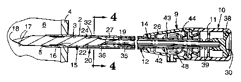
Figure 1 is a perspective view of a first
embodiment of trocar assembly according to the present
invention that is placed within a cannula assembly that
includes a valve which affords passage of insufflating
gas into the body cavity and which restricts loss of
insufflating gas from the body cavity when the trocar
assembly is removed from the cannula assembly;
Figure 2 is a slightly enlarged sectional
view of the trocar and cannula assemblies shown in
Figure 1 with portions broken away or omitted to show
details;
Figure 3 is an exploded, enlarged perspective
view of portions of the cannula assembly of Figure 1;
Figure 4 is an enlarged sectional view of the
first embodiment of trocar assembly and the cannula
assembly shown in Figure 2, taken approximately along
lines 4-4 of Figure 2;
Figure 5 is a sectional view of the trocar
assembly of Figure 1 removed from the cannula assembly
WO 95/07663 2 ~ ~ ~ g 6 9 PCT~S94/08930
_ g _
and illustrating an obturator distal end portion being
released into a disposal container and with portions
broken away to emphasize details;
Figure 5A is a sectional view of the trocar
assembly of Figure 1 removed from the cannula assembly
and illustrating an obturator distal end portion that
is released into a disposal container;
Figure 6 is a side view which illustrates a
rack of replacement distal end portions;
Figure 7 is a sectional view of a second
embodiment of trocar assembly according to the present
invention and a cannula assembly;
Figures 8 and 9 are perspective views of a
disposal container which sequentially illustrates the
removal of a used or dull obturator distal end portion
for the embodiment of trocar assembly shown in Figure 7
wherein:
Figure 8 is a perspective view of the
disposal container with a portion of the obturator
distal end portion (of the trocar assembly of Figure 7)
placed within the disposal container, and which omits
details of the detent means to emphasize other details;
Figure 9 is a perspective view of the
disposal container closed about the obturator distal
end portion and with the obturator's proximal portion
separated from the obturator's distal end portion;
Figure 10 is a side view of an obturator's
distal end portion with a conical cutting portion;
Figure 11 is a top view of a portion of a
third embodiment of trocar assembly according to the
present invention illustrating the distal end portion
of the obturator;
Figure 12 is a top view of another portion of
a third embodiment of trocar assembly according to the
present invention illustrating the proximal end portion
of the obturator and with portions broken away to show
details;
WO 95/07663 PCT/US94/08930
_ g _
Figure 13 is a side view of the distal end
portion shown in Figure 11 taken approximately ninety
(90) degrees from that view;
Figure 14 is a side view of the proximal end
portion of Figure 12 taken approximately ninety (90)
degrees from that view;
Figure 15 is a side view of a proximal
portion and a plurality of different styles or types of
distal end portions according to a fourth embodiment of
the present invention; and
Figure 16 is a top view of a kit according to
the fourth embodiment of the present invention which
illustrates a proximal portion of a trocar assembly
packaged with a plurality of different styles or types
of distal end portions.
Detailed Descrit~tion of the Preferred Embodiment
Referring now to Figures 1, 2 and 4 and 5 of
the drawing there is shown an embodiment of a trocar
device or assembly generally designated by reference
character 10. The trocar assembly 10 is preferably
used in laparoscopic surgery, however, the trocars
described herein may also be used in other surgeries
such as orthopedic surgery or in closed wound drainage
applications.
Figure 1 illustrates the trocar assembly 10
placed within a cannula assembly 9 which includes a
cannula 2. The trocar assembly 10 may be completely
removed from the cannula assembly 9 by sliding the
trocar assembly 10 longitudinally relative to the
cannula assembly 9.
The trocar assembly 10 is adapted for
placement within the cannula 2 to facilitate inserting
the cannula 2 through a wall 4 (Figure 2) having tissue
defining a body cavity 6. For example the trocar
assembly 10 may be used to insert an access tube or
cannula 2 through an abdominal wall of a patient.
WO 95/07663 PCT/US9=1/08930
2171969
The cannula 2 comprises interior surfaces 3
defining a lumen and a distal end 5 having an opening.
The cannula 2 has an enlarged fixture formed from left
and right portions 42 and 43. The fixture has a
chamber at its proximal end. There is an opening at
the proximal end of the chamber through which the
trocar fits while the cannula 2 is inserted in the body
cavity, and through which surgical instruments can
access the interior of the body cavity after the
cannula 2 is in place and the trocar assembly is
removed.
Figure 3 is an exploded perspective view of
the cannula assembly 9. The cannula assembly 9 is the
type which affords passage of insufflation gas through
valve 41 to inflate the abdominal cavity and which
restricts the passage of insufflation gas from the
abdominal cavity after the trocar assembly 10 has been
removed from the cannula assembly 9.
The cannula assembly 9 is similar to the
cannula assembly described in U.S. Patent No.
5,152,754. As best seen in Figure 3, the cannula
assembly 9 includes first 42 and second 43 housing or
handle portions which may be assembled by a snap fit
with a suitable adhesive (e. g. a "Prism" T.M. Loctite
adhesive generally available from Loctite corporation
of Newington, Connecticut) to form a chamber 44. There
is an opening at the proximal end of the chamber 44
through which the trocar fits while the access tube or
cannula 2 is inserted in the body cavity, and through
which surgical instruments can access the interior of
the body cavity after the cannula 2 is in place and the
trocar is removed.
A trap door valve member 48 having a sealing
gasket is pivotally mounted adjacent the opening to
close the opening. The valve member 48 is operated by
a pushbutton 45 mounted for movement relative to first
and second handle portions 42, 43. The pushbutton 45
W O 95/07663
PCT/US94/08930
- 11 -
is reciprocally mounted in a sealing gasket 46, and is
resiliently spring biased outwardly by spring 47.
A link 49 extends from the pushbutton 45 to
the valve member 48. Manually pushing the pushbutton
45 inwardly moves the valve member 48 open. The bias
of the spring 47 causes the button 45 to move outwardly
when it is release thereby causing the valve member 48
to close. The cannula assembly 9 also includes an
insertion funnel guide adapter 37, an adapter seal
stabilizer 34 and an O-ring 40.
The trocar assembly 10 comprises a handle 11
with a generally rounded configuration that can be
comfortably gripped by the user. The handle 11 may be
placed adjacent the chamber in the cannula assembly 9,
and may comprise first and second polymeric portions
which may be assembled by a snap fit with a suitable
adhesive (e. g. a suitable "Prism" T.M. Loctite adhesive
generally available from Loctite Corporation of
Newington, Connecticut).
The handle 11 is releasably, fractionally
attached to the cannula assembly 9 so that after the
trocar 10 inserts the cannula 2 in the wall 4, the
trocar 10 can be removed so that the cannula 2 can be
used to introduce surgical instruments (e.g. such as a
clip applier or stapler) into the body cavity. The
handle 11 optionally includes flanges F which cooperate
with grooves on the first and second portions 42 and 43
to restrict relative rotation between the handle 11 and
the cannula assembly 9.
The trocar assembly 10 also includes an
obturator 12 extending from the handle 11 and having an
imaginary axis A (Figure 1). The obturator 12
comprises a proximal portion 14, and a distal end
portion 15 comprising a base part 16 and having three
generally planar surfaces 17 intersecting to form three
cutting edges and a point 18 at the distal end of the
obturator 12 adapted to pierce the wall 4.
WO 95/07663 PCT/US94/08930
- 12 -
Figure 10 illustrates an alternative form of
distal end portion 15' which includes a conical portion
with a point 18'. Generally, the distal shape of the
cutting surfaces of the obturator may take any suitable
shape such as but not limited to triangular or square
based pyramids or hollow parabolic, as long as the
obturator is adapted to cut tissue. Additional
alternative forms of the distal end portion are
described in conjunction with the embodiment of the
present invention shown in Figures 15 and 16.
The trocar assembly 10 also includes detent
means 20 for releasably connecting the proximal portion
14 of the obturator to the distal end portion 15 of the
obturator 12 and optionally for restricting relative
rotation between the distal end portion 15 and the
proximal portion 14. The detent means 20 comprises a
groove part 22 extending at least partially about the
axis A of the obturator 12 located on one of the
proximal 14 and distal end 15 portions (in the species
shown in Figures 1, 2, 4 and 5, the groove part 22 is
located on the distal end portion 15) and a detent part
24 situated on the other of the proximal 14 and distal
end 15 portions (in the species shown in Figures 1, 2,
4 and 5, the detent part 24 is located on the proximal
part 14). The detent part 24 is adapted to releasably
engage the groove part 22.
When the obturator 12 is placed within the
cannula 2, the groove part 22 and the detent part 24
are situated within the lumen of the cannula 2 and the
cutting edges project beyond the distal end 5 of the
cannula 2 (see Figure 2).
As best seen in Figure 2, 4 and 5, the detent
means 20 comprises a plurality of detent parts 24
having leaf spring members 27 movable radially
outwardly (see Figure 5) to accept or release the
groove part 22 on the distal end portion 15. When the
trocar assembly 10 is placed within the cannula 2, the
WO 95/07663 ~ PCT/ITS94108930
- 13 -
interior or inside surfaces 3 defining the cannula
lumen prevent the leaf spring members 27 :from moving or
deflecting radially outwardly to prevent release of the
distal end portion 15 from the proximal portion 14.
This prevents the distal end portion 15 from being
accidently or inadvertently dropped into the body
cavity 6 during a surgical procedure.
As shown in Figures 2, 4 and 5, the proximal
portion 14 may comprise a housing member 26 constructed
from any suitable material such as stainless steel, a
polycarbonate or polypropylene. The proximal portion
14 also includes the leaf spring members 27 (which has
the detent 24) which may be constructed from any
suitable, flexible material such as, but not limited to
a stainless steel, polycarbonate or polypropylene. The
leaf spring members 27 may be adhesively attached to
the housing member 26.
The leaf spring members 27 should be flexible
enough to afford radially outward movement. so that the
distal end portion 15 may be received and yet resilient
enough to allow the detent part 24 to spring back into
engagement with the groove 22.
The distal end portion 15 may be constructed
from any suitable material such as but not limited to a
stainless steel, polycarbonate or polypropylene.
Aluminum may also be used to construct the distal end
portion 15. Since, the distal end portion is
disposable, the material used to construct the distal
end portion 15 is preferably inexpensive yet affords
construction of sufficiently sharp and durable cutting
surfaces.
As best seen in Figure 4, the groove part 22
includes a plurality of axially extending ribs 25.
When the proximal portion 14 is attached to the distal
end portion 15 (as shown in Figures 1 and 4), the ribs
25 are situated between the leaf spring members 27 to
restrict relative rotation between the proximal 14 and
WO 95/07663 ~ i ~ 19 6 9 PCT/US94/08930
- 14 -
distal end 15 portions, and also between the distal end
portion 15 and the cannula 2. Alternatively, the ribs
25 may be completely omitted from the embodiment shown
in Figures 1, 2, 4 and 5.
Optionally, the trocar assembly 10 further
includes means 30 for releasing the distal end portion
without requiring the user to grasp the distal end
portion 15. The means 30 comprises the distal end
portion 15 having caroming surfaces 31, and the proximal
10 portion 14 having bearing surfaces 32. The means 30
also includes an ejector rod 35 at least partially
located within the proximal portion 14.
The ejector rod 35 is axially movable
relative to the proximal portion 14. The ejector rod
15 35 has a distal end 36 adapted to abut a proximal end
19 of the distal end portion 15. The means 30 also
includes a button member 38 mounted to the ejector rod
35. The button member 38 is axially movable between
release (Figure 5A) and rest/grasp (Figure 2)
positions. Between the rest/grasp and the release
positions, the leaf spring members 27 deflect radially
outwardly relative to the axis A taking the detent
parts 24 out of engagement with the groove parts 22 to
afford passage and release of the distal end portion 15
(see Figure 5). A biasing means in the form of a coil
spring 39 biases the button member 38 toward the rest
position.
When the trocar assembly 10 is removed from
the cannula 2, the button member 38 may be moved from
the grasp to the release position so that the caroming
surfaces 31 may engage the bearing surfaces 32 and move
portions of the leaf spring members 27 radially
outwardly to release the distal end portion 15 (Figure
5). It should be noted that when the trocar assembly
is located within the cannula assembly 9, the interior
surfaces 3 of the cannula 2 prevent the leaf spring
members 27 from deflecting radially outwardly.
WO 95/07663 PCT/US94/08930
- 15 -
Figure 6 illustrates a rack 28 of replacement
distal end portions which may optionally include a
cover 29. When the cover 29 is removed, the rack 28
exposes the proximal end 19 of a plurality of the
replacement distal end portions 15 so that a user may
conveniently slide the proximal end portion 14 onto the
distal end portion 15 so that the detent part 24
engages the groove part 22. The rack 28 may include
diverse distal end designs (e. g. distal tips with
different shaped cutting surfaces such as conical,
pyramidal etc.) according to the needs of a particular
surgical procedure.
Operation
The trocar assembly 10 will be used to
describe a method according to the present invention.
The trocar assembly 10 optionally includes a protective
cap (not shown) over the point 18 that is removed prior
to use of the trocar assembly 10. The cannula 2 is
initially installed over the distal end of the trocar
assembly 10. The user grasps the handle 11 and first
and second portions 42 and 43 of the trocar and cannula
assemblies 9 and 10 with the palm of the hand.
The trocar assembly 10 is then advanced
against the wall 4 of a patient (Figure 2). The user
continues to advance the trocar assembly 10 until the
wall 4 is penetrated. As the wall 4 is being
penetrated, the interior surfaces 3 of cannula 2
prevents the leaf spring parts 27 from springing
radially outwardly to restrict the opportunity for the
distal end portion 15 from inadvertently or accidently
falling into the abdominal cavity 6.
Once the cannula 2 has penetrated through the
wall 4, the user may then grasp the first and second
portions 42 and 43 of the cannula assembly 9, and pull
the trocar handle 11 axially and proximally relative to
the cannula 2, leaving the cannula 2 in the abdominal
WO 95107663 y PCT/US94/08930
- 16 -
wall 4. As noted above, the cannula assembly 9 may
have a trap-door valve that closes the cannula 2 when
the trocar is withdrawn to prevent the escape of
insufflation gas from the abdomen.
The trocar 10 can be quickly prepared for
reuse (on the same patient) by pressing the button
member 38 and allowing the used distal end portion 15
to fall into a disposal container 7 (Figures 5 and 5A),
and then snapping another, replacement distal end
portion 15 with sharp cutting surfaces onto the
proximal portion 14. Optionally, the trocar assembly
10 may be sterilized, if necessary, by techniques well
known in the art such as Gamma Radiation, steam or
Ethylene Oxide (Et0) gas sterilization. Another
cannula 2 can then be placed over the trocar assembly
10, and the procedure repeated on the same or a
different patient. This procedure affords a clean,
sharp distal tip end portion 15 which requires minimal
handling by medical personnel.
Referring now to Figures 7, 8 and 9 of the
drawing, there is shown a second alternative embodiment
of trocar assembly according to the present invention,
generally designated by the reference character 50.
The assembly shown in Figure 7 includes the
trocar assembly 50 and a cannula assembly 9A (including
cannula 2A). Unlike the cannula assembly 9, the
cannula assembly 9A does not include a trap door for
preventing the escape of insufflating gas.
The trocar assembly 50 has many elements
which are essentially the same or identical as elements
in the trocar assembly 10 which are identified by the
same reference character to which the suffix "A" has
been added.
The trocar assembly 50 comprises a handle 11A
that is releasably, frictionally attached to the
cannula assembly 9A. The trocar assembly 50 also
includes an obturator 12A extending from the handle
WO 95/07663 PCT/US94/08930
- 17 -
11A. The obturator 12A comprises a proximal portion
14A, and a distal end portion 15A comprising a base
part 16A and having three generally planar surfaces 17A
intersecting to form three cutting edges and a point
18A. Optionally, the trocar assembly 50 may include a
cleanout or flush channel extending between the inner
surfaces of the obturator 12A and a proximal end of the
handle 11A.
The trocar assembly 50 also includes detent
means 20A for releasably connecting the proximal
portion 14A of the obturator to the dista7L end portion
15A of the obturator 12A. The detent means 20A
comprises a groove part 22A located on one' of the
proximal 14A and distal end 15A portions and a detent
part 24A situated on the other of the pro~s:imal 14A and
distal end 15A portions.
The decent means 20A comprises a plurality of
detent parts 24A having leaf spring members 27A movable
radially outwardly to accept or release th.e groove part
22A on the distal end portion 15A. When the trocar
assembly 50 is placed within the cannula 2A, the
interior or inside surfaces 3A defining the cannula
lumen prevent any portion of the leaf spring members
27A from moving or deflecting radially outwardly, and
thus prevent release of the distal end portion 15A from
the proximal portion 14A.
Unlike the trocar assembly 10, t:he trocar
assembly 50 does not include the means 30. Instead the
trocar assembly 50 uses engagable surfaces 51 located
on the distal end portion 15A. For example, a user may
manually engage the surfaces 51 and simply pull the
proximal portion 14A axially relative to the distal end
portion 15A to remove a used or dull distal end
portion.
Also unlike the trocar assembly 10 and as
best,seen in Figure 9, the distal portion :15A of the
obturator 12A does not include ribs 25 and instead has
WO 95107663 ~ I ~ l 9 6 9 PCTIUS94/08930
- 18 -
a cylindrical portion 53. The detents 24 and the leaf
spring members 27A are not obstructed and thus, the
distal portion 15A is free to rotate relative to the
cannula 2A and proximal portion 14A to afford a
"drilling action" preferred by some surgeons.
The engagable surfaces 51 are spaced from the
cutting edges and are adapted to be grasped by a user.
When the trocar assembly 50 is removed from the
cannula, a user may manually grasp the distal end
portion 15A by the engagable surfaces 51 and pull the
distal end portion 15A away from the proximal portion
14A to cause the leaf spring members 27A to move
radially outwardly to release the distal end portion
15.
Figures 8 through 9 illustrate an
alternative, preferred method of removing the distal
end portion 15A from the proximal portion 14A of the
trocar assembly 50 which includes a means for releasing
the distal end portion without requiring the user to
grasp the distal end portion generally designated by
reference character 52.
The means 52 comprises a disposal container
having first 56 and second 57 sections each having
manually engagable outer surfaces 58 and distal end
portion engaging surfaces 59 spaced from the manually
engagable outer surfaces 58. The disposal container
includes hinge 55 and latch 60. The disposal container
is preferably integrally constructed from an
inexpensive material such as, but not limited to a
polycarbonate, so long as it acts as a barrier to
prevent the cutting surfaces of the obturator from
coming into contact with a person (e.g. such as a
surgeon or processor of medical waste).
The disposal container's first 56 and second
57 portions are movable between an open position
(Figure 8) where they receive a distal end portion 15A
of trocar assembly 50 and a closed position (Figure 9).
WO 95/07663 ~ PCT/US94/08930
- 19 -
In the closed position, (1) the distal end portion
engaging surfaces 59 grasp portions of the distal end
portion (e.g. the engagable surfaces 51), (2) the
disposal container encloses the cutting surfaces of the
distal end portion 15A and provides a barrier to
restrict exposure to the cutting surfaces, and (3) a
user may grasp the manually engagable surfaces 58 of
the disposal container and move the disposal container
axially away from the proximal portion 14A of the
trocar assembly 50 to separate the distal end portion
15A from the proximal portion 14A without requiring the
user to grasp the distal end portion 15A.
Referring now to Figures 11 through 14 of the
drawing, there is shown a third alternative embodiment
of trocar assembly according to the present invention,
generally designated by the reference character 100.
The trocar assembly 100 is adapted for use
with cannula assemblies similar to the cannula
assemblies 9 and 9A. The trocar assembly 100 comprises
a handle (omitted to show detail but similar to 11 or
11A) that is releasably, fractionally attached to the
cannula assembly. The trocar assembly 100 also
includes an obturator 112 extending from the handle.
The obturator 112 comprises a proximal portion 114, and
a distal end portion 115 comprising a base part 116 and
having three generally planar surfaces 11'7 intersecting
to form three cutting edges and a point 118.
Alternatively the cutting surfaces may comprise any
suitable, desired shape.
The trocar assembly 100 also includes detent
means 120 for releasably connecting the proximal
portion 114 of the obturator to the distal end portion
115 of the obturator 112. The detent means 120
comprises a groove part 122 located on one of the
proximal 114 and distal end 115 portions (in Figures 12
and 14, the groove part 112 is shown on the proximal
portion 114) and a detent part 124 situated on the
WO 95/07663 I PCT/US94/08930
- 20 -
other of the proximal 114 and distal end 115 portions
(in Figures 11 and 13, the detent part 124 is shown on
the distal portion 115).
The detent part 124 comprises two lug
portions 126 and 127. The lug portion 126 has a
semicylindrical outer surface sharing an axis with the
axis A' of the obturator 112. The lug portion 127 may
also have a semicylindrical outer surface that does not
share an axis with the obturator 112, or alternatively,
as shown in Figure 13, the lug portion 127 may simply
be a flat surface.
To construct the obturator 112, the distal
end portion 115 would be placed into the proximal
portion 114 from the side or top and then the obturator
112 would be placed within the lumen of a cannula
assembly where the interior surfaces of the cannula
assembly (e. g. 3 or 3A) would lock or secure the distal
end portion in place. The lug 126 is believed to
restrict or prevent rotation of the distal end portion
115 from rotating relative to the proximal portion or
the cannula assembly.
Referring now to Figures 15 and 16 of the
drawing, there is shown a fourth alternative embodiment
of the present invention, generally designed by the
reference character 200.
The kit assembly 200 is provided for use
during a laparoscopic surgical procedure. The kit
assembly 200 comprises a proximal portion 201 of a
obturator having a handle 202 adapted to be manually
grasped, and attachment means for releasably connecting
the proximal portion 201 of the obturator to a distal
portion (discussed in greater detail below).
Examples of different distal portions are
shown in Figure 15 as reference characters 210-216.
Each of the distal portions 210-216 are different from
each other within the scope of the present invention.
Preferably, each of the distal portions have
CA 02171969 2005-03-03
- 21 -
substantially the same outer diameter D (relative to a
radius taken from the longitudinal axis) so that they
may each fit through the same'diameter cannula lumen.
~ For example, each of the distal portions may fit
through a 10 mm cannula.
Distal end portion 210 comprises a conical
shaped tip for cutting tissue. This distal portion is
also shown in Figure 10. Conical tip trocars are
preferred by some surgeons. A conical shaped tip on an
obturator is shown in U.S. Patent No. 5,002,557.
Reference character 211 depicts a distal
portion having a pyramid-shaped distal end. when it is
said that the distal end portion is pyramid shaped, it
is meant that the distal end portion has at least three
substantially-planar face surfaces 231 situated at an
angle relative to each other. The face surfaces 231
intersect at cutting surfaces 232 that are sharpened to
cut tissue. The cutting surfaces 232 culminate in a
sharp tip 233. Examples of obturators having pyramid-
shaped cutting surfaces are shown in U.S. Patent No.'s
3,994,287, 4,177,814 and 5,152,754.
Reference character 214 illustrates distal
end comprising a customized pyramid-shaped distal end
portion 214. The illustrated customized pyramid-shaped
distal end portion 214 is known as a bilevel style
obturator tip which is considered to be quite sharp.
Like the distal end portion 211, the distal end portion
214 has a plurality of planar face surfaces 231,
cutting surfaces 232 and a sharpened tip 233. However,
unlike the distal end portion 211, the distal end
portion 214 includes planar face surfaces 240 situated
at a angle relative to the face surfaces 231.
Alternative examples of obturators that have customized
pyramid-shaped distal end portions are shown in U.S.
CA 02171969 2005-03-03
- 22 -
Patent No. 5,057,082,,
Distal portion 212 is generally identical to
distal portion 211 except that distal portion 211 is
elongate along its longitudinal axis compared to distal
portion 211. The elongate distal portion 211 is
believed to be particularly desirable for use in
conjunction with an elongate cannula during a procedure
on an obese patient to ensure that the trocar and
cannula completely piece the abdominal wall.
Distal portion 213 comprises a blunt distal
end 218. For example, the distal end may comprise a
substantially semi-spherical shaped surface.
Commercially, a blunt distal end trocar is commonly
referred to as a Hasson-type obturator and is generally
available from Snowden Pencer of Tucker, Georgia.
Hasson-type cannula are disclosed in U.S. Patent No.'s
3,817,251 and 4,617,933.
Distal portions 215 and 216 are further
examples of different types of distal end portions
according to the present invention. Distal portion 215
includes a cutting surface that is substantially
perpendicular to the longitudinal axis of the distal
portion, similar to the cutting surface shown in Figure
1 of U.S. Patent No. 4,535,773.
Distal portion 216 comprises elliptical
shaped cutting surfaces 219. Obturators having
elliptical-shaped cutting surfaces are shown, for
example, in U.S. Patent No.'s 5,104,382, 5,223,951, and
5,226,426.
The proximal portion includes an attachment
means for releasably attaching the proximal portion 201
to one of the distal portions 210-216. Each of the
distal portions 210-216 include an means, cooperable
with the attachment means, for releasably connecting
them to the proximal portion 201. For example, distal
portions 210 may each include a groove part 250 adapted
PCT/US94/08930
W O 95/07663 2 i ~ 19 6 9
- 23 -
to be releasably engaged by a detent part. (not shown in
Figure 15 and 16) on the proximal portion 201. The
attachment means may comprise any of the detent means
described above.
According to one aspect of the present
invention, the proximal portion 201 may be packaged
separately from any distal portions. Such a kit allows
surgeons to use a proximal portion with a desired
distal portion. Thus, the trocar is assembled
according to a surgeon's preference rather than the
dictates of the package.
Example 1
With reference to Figure 16, the kit assembly
200 may comprise three distal portions 211, 212 and 213
and one proximal portion 201 situated within package
220. Alternatively, the package may comprise the rack
shown in Figure 6 except that the proximal portion 201
is added.
The kit 200 may be used during a laparoscopic
surgical procedure. Typically, the abdominal cavity is
initially insufflated with a pneumoneedle. Next, a
trocar such as the trocar shown in U.S. Patent
5,152,754 may be used to insert a cannula through which
an endoscope may be threaded.
The endoscope may reveal to the surgeon that
a conventional pyramid-shaped distal end portion 211
may be used to insert a second cannula at one portion,
but that because of obesity of the patient (for
example) the elongate distal end portion :?12 should be
used to insert another cannula at a different point.
Finally, due to patient sensitivity or other reasons,
the endoscope may reveal that only a Hasson-type distal
end portion 213 should be used to insert a cannula at a
particular portion.
It should be noted that at the end of such a
procedure, only one proximal portion 201 need be
WO 95/07663 ~ 1719 6 9 PCT/US94/08930
- 24 -
disposed, thus providing the potential for cost savings
and reduced waste. Also, requiring sterilization of
only the proximal portion 201 may simplify
sterilization procedures.
The present invention has now been described
with reference to several embodiments thereof. It will
be apparent to those skilled in the art that many
charges or additional can be made in the embodiments
described without departing from the scope of the
present invention. For example, the trocar assembly 50
may include ribs similar to the ribs 25 shown in Figure
4; and the cannula assembly 9A shown in Figure 7 may be
replaced with a cannula assembly which is substantially
identical to the cannula assembly 9 shown in
conjunction with the first embodiment of trocar
assembly 10 (e. g. it may include a trap door valve
mechanism, etc.). Additionally the trocar assembly 10
may be used in conjunction with a cannula assembly
similar to the cannula assembly 9A. Also, the detent
part 24 of the trocar assembly 10 may be located on the
distal end portion 15 and the groove part 22 may be
located on the proximal portion 14.