Note: Descriptions are shown in the official language in which they were submitted.
'''~~ 2171987
[Title of the Document] Specification
[Title of the Invention] Multi-direction camera
[Detailed description of the Invention]
[0001]
[Field of the Invention]
The present invention relates to a multi-direction
camera for sensing images which are entering from many
directions such as directions to the left and right of a
vehicle, and particularly to an improved multi-direction
camera capable of simultaneously taking pictures in a
plurality of directions.
[0002]
[Prior Art]
For example, when an automobile enters, for example, a
crossing, the driver must be aware of other oncoming
- 2 -
CA 02171987 2000-11-07
vehicles for safety irrespective of whether there are traffic lights at the
crossing or
not. If the crossing is a blind corner, it is difficult to check the traffic
conditions on
the roads that cross the road on which the automobile is traveling.
In view of the aforementioned problem, Japanese Unexamined Utility
Model Publication Hei No.1-109447 discloses a multi-direction camera where the
traffic condition on the crossing road may be checked for safety on the basis
of
the images taken by a camera mounted on the forward end portion of the
automobile.
A detailed description of the prior art and of the present invention is
provided herein below, with reference to the following drawings, in which:
Fig. 1 is a cross sectional view showing an essential part of the first
embodiment of the present invention.
[Fig. 2]
Fig. 2 is an exploded perspective view of the construction shown in Fig. 1.
[Fig. 3]
Fig. 3 illustrates a video image in which the construction shown in Fig. 1
prevents a ghost from appearing.
[Fig. 4]
Fig. 4 illustrates a video image in which the construction shown in Fig. 1
provides a clear boundary line.
[Fig. 5]
Fig. 5 is a cross-sectional view of an essential part of the second
embodiment of the present invention.
[Fig. 6]
Fig. 6 is a top view of an automobile equipped with a multi-direction
camera.
[Fig. 7]
Fig. 7 is a cross-sectional view of a prior art multi-direction camera.
[Fig. 8]
Fig. 8 illustrates a video image in which a ghost image appears due to the
3
CA 02171987 2000-11-07
prior art construction shown in Fig. 7.
[Fig. 9]
Fig. 9 illustrates a video image taken with a prior art camera in which there
is nothing to indicate the boundary between the left image and the right
image.
[Fig. 10]
Fig. 10 illustrates a blurred boundary between the left image and the right
image in the prior art shown in Fig. 7.
Figs. 6-10 show a prior art multi-direction camera. Fig. 6 is a top view of
an automobile B on which a multi-direction camera A is mounted, and shows
angles of view 01 and 02 that the camera shoots images in the directions to
the
left and right of the automobile. The multi-direction camera A is constructed
as
follows: As shown in Fig. 7, the multi-direction camera A includes a case C,
cover
D, mirror E, lens F, lens mount G, circuit board H, and windows I and J. The
mirror E reflects light L1 which is incident from the left and right
directions with
respect to an edge line K of the mirror E. The lens F receives the reflected
light
and causes an image to be formed on an image-sensing device M in the form of
a CCD (charge coupled device) mounted on the circuit board H. In this manner,
the multi-direction camera A takes the left and right images viewed in the
directions to the left and right of the automobile B, the angle of view being
01 and
02, respectively.
[0003]
[Subject to be Solved by the Invention]
However, the aforementioned prior art multi-direction camera has several
drawbacks.
A first drawback is that ghost images appear in the video image due to
various reflections occurring within the multi-direction camera A. The
principle of
how these ghost images are produced will be described with reference to Figs.
7
and 8. For example, at night, the left window I receives light beams L1 from
light
sources N such as headlights of other vehicle oncoming from the left side of
the
automobile. The light beams L1 are reflected by the mirror E and are then
received by the lens F which in turn forms images on the CCD device M. Thus,
4
CA 02171987 2000-11-07
the image of the head light sources N appear in the left image a as shown in
Fig.
8. If there is no light source on the road to the right of the automobile, no
image
should appear in the right image b in Fig. 8. However, light beams L2 incident
through the left window I are reflected by the right window J as shown in Fig.
7,
and are further reflected by the mirror E. The reflected light beams are
received
by the lens F which in turn forms images of the light beams L2 on the CCD
device M. The light beams L2 result in a ghost image of the light sources N in
the
right image b as shown in Fig. 8.
[0004]
A second drawback is that the left and right images a and b formed on the
CCD device M are not clearly bounded by a boundary line c. For example, there
is nothing to indicate the boundary c as shown in Fig. 9, so that the left
image a
is not clearly distinguished from the right image b or the left and right
images are
not quite focused near the boundary c as shown in Fig. 10. The latter case is
due
to the fact that the edge line K of the mirror E appears as a part of the
image, the
boundary line c but is not quite focused since the edge line K is too close to
the
lens F to be accurately focused. In order to solve the second drawback, a
superimposing circuit may be employed in order to display the left and right
images a and b with the boundary line c electrically superimposed
therebetween.
However, superimposing a boundary line c is not preferable since such
construction increases the cost of the multi-direction camera.
The present invention is to solve the aforementioned second drawback
and to provide an improved multi-direction camera in which a clear boundary
line
is formed between a plurality of sensed images without using electrical means.
[0005]
[Means for Solving the Subject]
In order to solve the aforementioned drawbacks, the invention provides
a multi-direction camera comprising a mirror having a plurality of reflecting
surfaces for reflecting light from a plurality of directions, said mirror
being
disposed in front of a lens, which receives the reflected light to form images
on
an image sensing device, a shield disposed at a location away from the lens
CA 02171987 2001-04-04
6
such that a part of an image of the shield serves as a boundary line between
the
images, wherein the mirror is enclosed by an opaque cover, the cover has a
transparent window opposing each of the reflecting surfaces, the window has a
frame, and part of the frame serves as a shield.
[0007]
The invention further provides a multi-direction camera comprising a mirror
having a plurality of reflecting surfaces for the reflecting light from a
plurality of
directions, said mirror being disposed in front of a lens, which receives the
reflected
light to form images on an image sensing device, a shield disposed at a
location
away from the lens such that a part of an image of the shield serves as a
boundary
line between the images, wherein the mirror is enclosed by an opaque cover,
the
cover has a transparent window opposing each of the reflecting surfaces, and a
length of tape is attached which extends inwardly from one side of a frame of
the
window in such a direction as. to partially cover the window to serve as a
shield.
[0008]
The invention also provides a multi-direction camera comprising a mirror
having a plurality of reflecting surfaces for reflecting light from a
plurality of directions,
said mirror being disposed in front of a lens, which receives the reflected
light to form
images on an image sensing device, a shield disposed at a location away from
the
lens such that a part of an image of the shield serves as a boundary line
between the
images, wherein the mirror is enclosed by an opaque cover, the cover has a
transparent window opposing each of the reflecting surfaces, and a shield is
provided
in proximity to the window wii:hin the cover.
[0009]
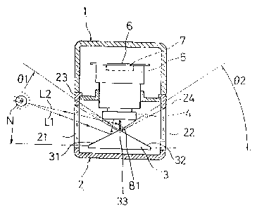
[First embodiment]
A first embodiment of the invention will now be described with reference to
Figs. 1-4.
In the figures, reference numeral I denotes a case, 2 a cover, 3 a mirror, 4 a
lens, 5 a lens mount, 6 a circuit board, 7 an image-sensing device, 8 a mirror
holder,
9 a fixing plate, 10 a packing, 11 and 12 vibroisolating rubber, 13 a filter,
14 a spacer,
and 15 a sub circuit board. Tlhese structural elements are described as
follows:
[0010]
The case 1 is formed of an opaque material and assembled to the cover 2 to
form a housing for the camera. A packing 10 is inserted between the case I and
the
cover 2 to form watertight construction.
[0011 ]
CA 02171987 2001-04-04
6a
The cover 2 is opaque except: for left and right windows 21 and 22. The cover
2 is
constructed by an appropriatE: process, for example, by insert-molding
CA 02171987 2000-11-07
the left and right windows 21 and 22 formed of a transparent acrylic resin
into an
opaque member, or by first forming the entire cover 2 of a transparent acrylic
resin and then applying a black pigment to the cover 2 with the left and right
windows 21 and 22 left unpainted.
The cover 2 has shields 23 and 24. The shields 23 and 24 are located
such that the lens 4 receives a part of each of black images of the shields 23
and
24, and the black images serve as a boundary line c between the left image a
and the right image b.
[0012]
The mirror 3 is molded of a synthetic resin and has triangular side
surfaces and two reflecting surfaces 31 and 32 on which aluminum is vapor-
deposited to form mirror surfaces thereon. The two reflecting surfaces 31 and
32
meet each other at an edge line 33.
[0013]
The lens 4 condenses the light reflected by the reflecting surfaces 31 and
32 of the mirror 3 and has a focal plane thereof on the surface of the later
described image-sensing device 7. The image-sensing device 7 is mounted on
the circuit board 6 and the lens 4 is mounted on the circuit board 6 by means
of
the lens mount 5. The lens mount 5 includes a spacer 14 and a filter 13 that
shields light having wavelengths other than visible light.
[0014]
The circuit board 6 carries a sub board 15 and terminals 61 as well as the
lens mount 5 supporting the lens 4. The terminals 61 outwardly extends through
holes 1 a in the case so that the circuit board 6 may be electrically
connected via
the terminals 61 to an AV (Audio Visual) apparatus, not shown, in the
passenger
space of the automobile. Between the circuit board 6 and the cover 2 are
inserted vibroisolating rubber members 11 and 12 which resiliently support the
circuit board 6.
[0015]
The image-sensing device 7 is a device for converting the light image
formed on the surface thereof into an electrical video signal. The image-
sensing
7
CA 02171987 2000-11-07
device takes the form of a CCD in this embodiment.
[0016]
The mirror holder 8 is formed of an opaque material in one piece with the
partitioning plate 81. The mirror holder 8 supports the mirror 3 and is fixed
to the
case 1 by means of a fixing plate 9. The partitioning plate 81 is provided
on the edge line 33 and extends toward the lens 4. The partitioning plate 81
optically isolates the two reflecting surfaces 31 and 32 one from the other so
that
light from one surface does not enter the light path through which light from
the
other surface enters. This construction eliminates a ghost image. Thus, the
light
incident through the left window 21 is reflected only by the left reflecting
surface
31 and does not enter the right reflecting surface 32. Likewise, the light
incident
through the right window 22 is reflected only by the right reflecting surface
32 and
does not enter the left reflecting surface 31.
[0017]
The multi-direction camera of the aforementioned construction is mounted
on the forward end portion of the automobile, for example, near the bumper.
The
lens is oriented to face a direction opposite to the direction of travel of
the
automobile. The left reflecting surface 31 is oriented to face a direction to
the left
of the automobile and the right reflecting surface 32 to face a direction to
the right
of the automobile. Orienting the lens to face a direction opposite to the
direction
of travel of the automobile, provides video images such that the images formed
on the surface of image sensing device 7 and displayed on the screen of the AV
apparatus are the same as what the driver sees by his eyes, i.e., the left
image
does not appear on the right in the displayed image and the right image does
not
appear on the left. This provides good visibility.
[0018]
The operation of the first embodiment will now be described. For
example, at night, when a light beam L1 enters through the left window 21 from
the light source N such as a head light of other vehicle to the left of the
automobile as shown in Fig. 1, the light beam L1 is reflected by the left
reflecting
surface 31 of the mirror 3 and the lens 4 receives the reflected light beam to
form
8
CA 02171987 2000-11-07
an image on the image sensing device 7. Thus, an image of the light source N
appears in the left image a as shown in Fig. 3. Since there is no light source
in
the direction to the right of the automobile, no image appears in the right
image b
in Fig. 3.
(0019)
The mirror 3 reflects light incident upon the reflecting surfaces 31 and 32
thereof from the directions to the left and right of the automobile, and the
angles
of view being 01 and 02, respectively. The lens 4 receives the light reflected
by
the mirror 3 to form images on the surface of the image sensing device 7. The
left image a is formed by the light incident through the left angle of view 01
and
the right image b by the light incident through the right angle of view 02 as
shown
in Fig. 4. The black images of the shields 23 and 24 received by the lens 4
are
also formed midway between the left image a and the right image b, serving as
the boundary line c. Since the shields 23 and 24 are away from the lens 4, the
images of the shields 23 and 24 are well focused to form a clear image of the
boundary line c.
[0020)
[Second embodiment)
Fig. 5 shows a second embodiment of the invention. The construction of
the second embodiment differs from the first embodiment in shields 25, 26, 27,
and 28. Here, only shields 25, 26, 27, and 28 are described and the
description
of the rest has been omitted. Although the shields 25 and 26 differ from the
shields 27 and 28 in type, they are shown in Fig. 5 together for convenience
of
explanation.
The shields 25 and 26 of one type are, for example, an opaque tape
sticked to the cover 2. The use of an opaque tape lends itself to, for
example,
improving existing products.
The shields 27 and 28 of the other type are in the form of a black plate
provided
within the cover 2. If the light entering the camera from outside is reflected
by the
surface of the shields 27 and 28, such reflection results in poor performance
of
the multi-direction camera. Therefore, the surfaces of the shields 27 and 28
are
9
CA 02171987 2000-11-07
preferably rough surfaces.
[0021 ]
[Advantages of the Invention]
The present invention provides a multi-direction camera in which a mirror
having a plurality of reflecting surfaces is disposed in front of a lens. The
mirror
reflects the light from a plurality of directions, and the lens receives the
reflected
light to form images on an image-sensing device. The camera is characterized
in
that a shield is provided at a location away from the lens such that part of
an
image of the shield serves as a boundary between the left and right images.
This
construction is advantageous in that a clear boundary line may be provided
between a plurality of video images without using electrical means.
Moreover, the present invention provides a multi-direction camera in which
the mirror is enclosed by an opaque cover, the cover has a transparent window
opposing each of the reflecting surfaces and a shield is provided. The shield
may
be formed by using a part of the frame of the window or by attaching a length
of
tape to one side of the frame which extends inwardly in such a direction as to
close the window, or by forming a shield in the proximity to the window within
the
cover. This facilitates formation of a clear boundary.
10