Language selection

Search

Patent 2172257 Summary

Third-party information liability

Some of the information on this Web page has been provided by external sources. The Government of Canada is not responsible for the accuracy, reliability or currency of the information supplied by external sources. Users wishing to rely upon this information should consult directly with the source of the information. Content provided by external sources is not subject to official languages, privacy and accessibility requirements.

Claims and Abstract availability

Any discrepancies in the text and image of the Claims and Abstract are due to differing posting times. Text of the Claims and Abstract are posted:

  • At the time the application is open to public inspection;
  • At the time of issue of the patent (grant).
(12) Patent: (11) CA 2172257
(54) English Title: CROSS BRACED VACUUM WASHER
(54) French Title: MACHINE A LAVER SOUS VIDE A MEMBRURES CROISEES
Status: Term Expired - Post Grant Beyond Limit
Bibliographic Data
(51) International Patent Classification (IPC):
  • B01D 33/067 (2006.01)
  • D21C 9/06 (2006.01)
(72) Inventors :
  • LEWIS, FREDERICK S. (United States of America)
(73) Owners :
  • INGERSOLL-RAND COMPANY
  • GL&V CANADA INC.
(71) Applicants :
  • INGERSOLL-RAND COMPANY (United States of America)
  • GL&V CANADA INC. (Canada)
(74) Agent: NORTON ROSE FULBRIGHT CANADA LLP/S.E.N.C.R.L., S.R.L.
(74) Associate agent:
(45) Issued: 2001-09-18
(86) PCT Filing Date: 1995-07-31
(87) Open to Public Inspection: 1996-02-15
Examination requested: 1997-09-18
Availability of licence: N/A
Dedicated to the Public: N/A
(25) Language of filing: English

Patent Cooperation Treaty (PCT): Yes
(86) PCT Filing Number: PCT/US1995/009615
(87) International Publication Number: WO 1996004061
(85) National Entry: 1996-03-20

(30) Application Priority Data:
Application No. Country/Territory Date
08/285,462 (United States of America) 1994-08-03

Abstracts

English Abstract


A washer drum is provided having a rotating cylinder (2) with unique cross bracing (15) which prevents twisting, reduces vortex
formation in radial inflow ports (6) formed between the outer head (11) and two adjacent radial ribs (21), and further provides support for
the decking (23) between closely spaced intermediate heads (11).


French Abstract

Machine à laver à tambour dont le tambour (2) comporte un systèmes de membrures transversales (15) spécial qui empêche les torsions, qui réduit la formation de tourbillons dans les orifices radiaux d'entrée de flux (6) ménagés entre la cloison extérieure (11) et deux nervures radiales contiguës (21) et qui sert de plus de support au couvercle (23) reliant deux cloisons intermédiaires (11) peu distantes.

Claims

Note: Claims are shown in the official language in which they were submitted.

Claims:
1. A washer drum of the type having generally longitudinal surface collection
channels delivering extracted liquid to radially formed channels interspaced
between
adjacent closely spaced heads disposed at one end of said drum, the
improvement
comprising:
a diagonal cross brace disposed in said radially formed channel between said
heads radially inward of said longitudinal surface collection channel and in
supporting contact therewith.
2. A washer drum according to claim 1, wherein:
said brace further serves to direct said liquid from said collection channels
to said
radially formed channels.
3. A washer drum according to claim 2, wherein:
said brace is attached to said adjacent spaced heads as a means for
transmitting
torque from one head to the other and said washer drum in either direction of
rotation.
4. A washer drum according to claim 2, wherein:
said brace is open to flow of said extracted liquid in a radially inward
direction.
5. A washer drum according to claim 4, wherein:
said brace further prevents vortex formation in said radially formed channel.

Description

Note: Descriptions are shown in the official language in which they were submitted.


'~ WO 96!04061 _ _ PCT/US95/09615
-1-
CROSS BRACED VACUUM WASHER
BACKGROUND OF T~iE INVENTION
This invention relates generally to vacuum washers and more
particularly to cross braced vacuum washers having a means for stiffening the
drum heads and preventing vortex formation of the filtrate in radial inflow
ports.
In the conventional end drainage washer the radial ports have little
resistance to relative rotation of the inner and outer head plates forming the
ports. The relative rotation allows twisting of the washer covering generally
comprised of a corrugated deck, winding wire and face wire. This results in
premature failure of the washer covering. In addition, vortexing of the
filtrate
in the radial ports allows gas to separate from the filtrate and hampers the
vacuum operation of the washer drum.
The foregoing illustrates limitations known to exist in present devices
and methods. Thus, it is apparent that it would be advantageous to provide an
alternative directed to overcoming one or more of the limitations set forth
above. Accordingly, a suitable alternative is provided including features more
fully disclosed hereinafter.
SUMMARY OF THE INVENTION
In one aspect of the present invention this is accomplished by providing
a cross braced vacuum washer including a washer drum of the type having
generally longitudinal surface collection channels delivering extracted liquid
to
radially formed channels interspaced between adjacent spaced heads, the
improvement comprising a brace disposed in the radially formed channel

CA 02172257 2000-10-03
2
between the heads radially inward of the longitudinal surface collection
channel and in supporting contact therewith.
According to a further broad aspect of the present invention there is
provided a washer drum of the type having generally longitudinal surface
collection channels delivering extracted liquid to radially formed channels
interspaced between adjacent closely spaced heads disposed at one end of the
drum. The improvement is comprised in that a diagonal cross brace is
disposed in the radially formed channel between the heads radially inward of
the longitudinal surface collection channel and in supporting contact
therewith.
The foregoing and other aspects will become apparent from the
following detailed description of the invention when considered in conjunction
with the accompanying drawing figures.
BRIEF DESCRIPTION OF THE DRAWING FIGURES
Figure 1 is an end cross section of a washer drum according to the
prior art taken through the end drainage portion of the drum;
Figure 2 is a partial longitudinal cross section of the drum showing
the filtrate flow path according to the prior art;
Figure 3 is a cross section of the end of a washer drum according to
the present invention taken through the end drainage portion of the drum;
Figure 4 is a partial longitudinal cross section of the drum showing
the cross braces of the present invention; and
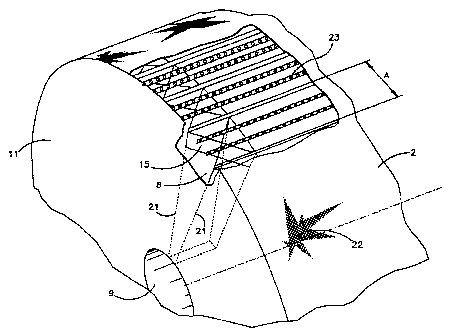
Figure 5 is a partial isometric depiction of a cross braced washer
drum according to the present invention.
DETAILED DESCRIPTION
A vacuum washer generally comprises a rotating cylinder usually
covered with a wire screen which is emersed in a pulp slurry contained in a
vat. The face of the cylinder is divided into longitudinal segments called
ports.
In operation, a differential pressure is applied across the face of the

217227
WO 96/04061 PCT/US95/09615
3
cylinder, which draws liquid out of the slurry through the ports leaving a
pulp
mat on the face of the cylinder. The differential pressure is created by
either
a drop leg or vacuum pump. A drop leg is a vertical column of liquid acting
as a siphon. Vacuum washers often use a pipe outside of the washer as a
drop leg to increase the available vacuum.
With the aid of a valve, the vacuum to some of the ports may be cut
off, allowing the pulp sheet to be removed more readily and to prevent
excessive air being sucked into the vacuum creating drop leg. A valueless
washer uses internal ports to create its own vacuum. The valueless washer
operates with a very low vacuum and generally does not require the use of a
valve.
Referring to Fig. 1 the end view of a vacuum washer according to the
prior art is shown and generally designated by the reference numeral 1. The
washer is comprised of a rotating cylinder 2 having a series of longitudinal
ports 4 for conducting filtrate collected on the surface of the drum to a
collection point such as the radial inflow ports 6 shown on Fig. 1. The radial
ports 6 conduct the collected filtrate to a central filtrate removal pipe 9,
as
best seen in Fig. 2.
The washer cylinder 2 is shown in Fig. 1 emersed in a vat 3 containing
a supply of pulp slurry 25 which is continuously provided to the vat at a
controlled rate. The pulp mat formed on the cylinder is shown being removed
by a doctor blade 5 and conducted to a fiber removal system 30.
As previously discussed, vacuum may be applied to the system as, for
example, in the sector, designated by the reference numeral 7, to aid in the

WO 96/04061 ~ PCT/US95109615
4
formation of the mat. The vacuum may be blanked off by a valve means in
1
the sector designated by the reference numeral 8. This assists in mat removal
and allows for the gentle initial mat formation on the submerging sectors of
the drum prior to vacuum application.
$ As shown in Figure 2, the surface of the drum is covered with a filter
screen or wire 22 which permits the recovered filtrate to pass through the mat
formation and screen wire into the longitudinal channels 4. The channels 4
direct the filtrate to the end of the drum where it enters the radial inflow
ports
6 formed between an outer head 11 and an inner head 12 in the end of the
drum 2. The radial ports 6 conduct the filtrate to a central discharge pipe 9
which in turn may be connected to a barometric vacuum leg or a vacuum
pump as the case may be (not shown).
Referring now to Figs. 3, 4, and 5, in a vacuum washer 10 according
to the present invention, a cross brace 15 is provided at the transition of
the
longitudinal port 4 and the radial port 12. The cross brace 15 is located at a
point radially inward of the longitudinal port 4 and being in supporting
contact
with the decking 23 (best seen in Fig. 5) which forms in fact the longitudinal
collecting channels. The radial inflow port 6 is formed between the outer
head 11 and the inner head 12 and two adjacent radial ribs 21, as best seen in
Fig. 5.
The cross brace 15 is open to flow in the radial direction so as to
receive the filtrate and permit its introduction into the radial inflow port
or
channel 6 for further conducting to the filtrate removal pipe 9. The cross
brace 15 is further connected to both the outside end plate 11 and the inside
end plate 12 thereby stiffening the end of the drum. This prevents relative

WO 96/04061 PCT/US95/09615
twisting between the inside end plate and the outside end plate as a result,
for
example, of the torque applied to the filtrate removal pipe which is used to
rotate the drum 2 in vat 3. In large drums with relatively thin plates, this
is
an important feature, particularly where high cost alloys are utilized due to
the
5 corrosive nature of the products being filtered.
In addition to the above benefit it has been observed in the prior art
that filtrate received in the radial inflow channels had a tendency to form a
vortex which promoted the separation of the filtrate and the entrained gas
therein. This substantially reduced the effectiveness of the vacuum as
compared to running the radial inflow channels in a slightly flooded fashion.
A further advantage of the cross bracing is the support provided to
the decking 23 suspended between the inner and the outer heads.
Thus, it is apparent that the cross bracing 15 provided according to
the present invention produces a threefold advantage of resisting torsional
twist between the inner and outer head, reducing the possibility of vortex
forming in the radial port and providing support to the decking bridged
between the inner and outer heads.

Representative Drawing
A single figure which represents the drawing illustrating the invention.
Administrative Status

2024-08-01:As part of the Next Generation Patents (NGP) transition, the Canadian Patents Database (CPD) now contains a more detailed Event History, which replicates the Event Log of our new back-office solution.

Please note that "Inactive:" events refers to events no longer in use in our new back-office solution.

For a clearer understanding of the status of the application/patent presented on this page, the site Disclaimer , as well as the definitions for Patent , Event History , Maintenance Fee  and Payment History  should be consulted.

Event History

Description Date
Inactive: Expired (new Act pat) 2015-07-31
Letter Sent 2014-12-29
Letter Sent 2009-06-19
Letter Sent 2003-10-10
Grant by Issuance 2001-09-18
Inactive: Cover page published 2001-09-17
Pre-grant 2001-06-07
Inactive: Final fee received 2001-06-07
Notice of Allowance is Issued 2001-01-09
Letter Sent 2001-01-09
Notice of Allowance is Issued 2001-01-09
Inactive: Approved for allowance (AFA) 2000-12-04
Inactive: First IPC assigned 2000-11-10
Letter Sent 2000-10-23
Amendment Received - Voluntary Amendment 2000-10-03
Reinstatement Requirements Deemed Compliant for All Abandonment Reasons 2000-10-03
Deemed Abandoned - Failure to Respond to Maintenance Fee Notice 2000-07-31
Inactive: Application prosecuted on TS as of Log entry date 1998-04-23
Inactive: RFE acknowledged - Prior art enquiry 1998-04-23
Inactive: Status info is complete as of Log entry date 1998-04-23
Letter Sent 1998-03-10
Letter Sent 1997-10-03
Reinstatement Requirements Deemed Compliant for All Abandonment Reasons 1997-09-25
Request for Examination Requirements Determined Compliant 1997-09-18
All Requirements for Examination Determined Compliant 1997-09-18
Deemed Abandoned - Failure to Respond to Maintenance Fee Notice 1997-07-31
Application Published (Open to Public Inspection) 1996-02-15

Abandonment History

Abandonment Date Reason Reinstatement Date
2000-07-31
1997-07-31

Maintenance Fee

The last payment was received on 2001-06-21

Note : If the full payment has not been received on or before the date indicated, a further fee may be required which may be one of the following

  • the reinstatement fee;
  • the late payment fee; or
  • additional fee to reverse deemed expiry.

Please refer to the CIPO Patent Fees web page to see all current fee amounts.

Owners on Record

Note: Records showing the ownership history in alphabetical order.

Current Owners on Record
INGERSOLL-RAND COMPANY
GL&V CANADA INC.
Past Owners on Record
FREDERICK S. LEWIS
Past Owners that do not appear in the "Owners on Record" listing will appear in other documentation within the application.
Documents

To view selected files, please enter reCAPTCHA code :


To view images, click a link in the Document Description column. To download the documents, select one or more checkboxes in the first column and then click the "Download Selected in PDF format (Zip Archive)" or the "Download Selected as Single PDF" button.

List of published and non-published patent-specific documents on the CPD .

If you have any difficulty accessing content, you can call the Client Service Centre at 1-866-997-1936 or send them an e-mail at CIPO Client Service Centre.


Document
Description 
Date
(yyyy-mm-dd) 
Number of pages   Size of Image (KB) 
Cover Page 1996-07-02 1 15
Abstract 1996-02-15 1 45
Claims 1996-02-15 1 32
Description 1996-02-15 5 181
Drawings 1996-02-15 3 92
Description 2000-10-03 5 193
Claims 2000-10-03 1 27
Cover Page 2001-08-27 1 41
Representative drawing 1997-06-16 1 15
Representative drawing 2005-10-19 1 18
Cover Page 2005-10-19 1 45
Courtesy - Abandonment Letter (Maintenance Fee) 1997-09-30 1 188
Notice of Reinstatement 1997-10-03 1 172
Courtesy - Certificate of registration (related document(s)) 1998-03-10 1 118
Acknowledgement of Request for Examination 1998-04-23 1 173
Courtesy - Abandonment Letter (Maintenance Fee) 2000-08-28 1 184
Notice of Reinstatement 2000-10-23 1 171
Commissioner's Notice - Application Found Allowable 2001-01-09 1 165
Courtesy - Certificate of registration (related document(s)) 2014-12-29 1 102
Correspondence 2001-06-07 1 62
Fees 2000-10-03 1 35
PCT 1996-03-20 3 95
Fees 1997-08-25 1 47