Note: Descriptions are shown in the official language in which they were submitted.
~1722~3
APPARATUS AND METHOD FOR ADJUSTING ROTOR BLADE TRACKIN~
TECHNICAL FIELD
This invention relates to helicopter rotors having 2
plurality of blades which move substantially in a common plane or
track and more particularly to means for adjusting individual
rotor blades to correct for lead/lag and flap track errors.
BACKGROUND
A helicopter rotor typically-includes two or more blades
which extend from a hub. For a particular type of rotor head such
as a bearingless main rotor (BMR), each blade typically has
associated with it a flexible spar which extends from the hub. As
disclosed in published European Patent Application, Publication
No. 0451082, the spar is used to connect the blade to the hub. A
torque tube surrounds the spar and has a control rod attached to
it which allows a pilot to change the blade pitch. As further
disclosed in published ~uropean Patent Application Pub. No.
451082, a pair of snubber dampers are disposed between the spar
and the torque tube to support the torque tube in proper
relationship with the spar. The snubber dampers transfer push rod
loads from the torque tube through the snubbers into the spar.
AMENO~D SHEET
~172283
As described and illustrated -in the afore-mentioned European
Patent Publication No. 451084, a snubber damper consists o~ a
series of spherical (snubber) and flat (damper) shims separated
by elastomeric layers. The two snubbers located above and below
the spar combine to form a spherical bearing which is used to
support and position the torque tube in a proper relationship to
the spar for limiting pitching and flapping motions. The damper
portions combine to provide sufficient damping of blade lead/lag
motion to maintain rotor stability.
As the rotor turns, the blades define a circular ~rack. ~ue
to the bolted attachment of the blades to the hub, or slight
differences in manufacturing tolerances, such as in the spring
rate of the snubbers, it is possible for tracking errors to
occur. Track errors may be exhibited by a change in spacing
between adjacent blades, i.e., a lead/lag error, or out of the
plane of the track, i.e. a flapping error. Even slight variations
at the hub can translate to large variations at the blade tips.
The result of these variations is that the rotor acts 2S an
unbalanced assembly with conseque~t vibration. It is beyond
present manufacturing capabilities to eliminate these variations.
~ 3~
WO 95/14608 ~ 1 7 ~ 2 ~ ~ PCT/US94/12057
SUMMARY OF INVENTION
It is an object of the present invention to provide means
for adjusting the position of each blade ext~n~ing from a rotor
hub to eliminate lead/lag tracking errors.
It is another object of the present invention to provide
means for adjusting the stiffness of each damper of a blade
assembly to reduce lead/lag and flap tracking errors.
These and other objects of the present invention are
achieved by a helicopter rotor having flexible spar means, hub
means retaining the spar means a plurality of blades extending
from the spar means, torque tube means associated with each blade
for adjusting blade pitch, snubber damper members disposed on
opposite sides of the flexible spar means for maintaining torque
tube position while transmitting pitch control changes to the
blade means from the torque tube means, and means for adjusting
the angular relationship of the spar means to the hub means to
correct lead/lag errors. In another embodiment of the invention,
the helicopter rotor includes means to adjust the stiffness of
the snubber damper members, to reduce lead/lag and flap tracking
errors.
In one embodiment, the torque tube has a lug fixed on an
upper surface thereof adjacent a top plate of a snubber damper.
The plate has a facing lug with a positioning screw disposed
therebetween, for adjusting the position of the upper plate of
the snubber relative to the torque tube to provide at least about
a 1/2 degree plus or minus adjustment of the blade lead/lag.
SUBSTITUTE SHEET ~RIJLE 26)
WO95114608 ~ 2 ~ 3 . PCT~$94/12057
Thus, the position of each blade could be adjusted to correct for
lead/lag errors and provide a rotor which is balanced to insure
correct spacing between blades under loaded conditions.
In another embodiment of the invention, the snubber damper
means comprise upper and lower dampers, each of which includes a
plurality of flat elastomeric plies with interleaved metal or
composite shims. The outermost elastomeric ply of one damper is
preferably of different stiffness than the outermost elastomeric
ply of the other damper. The outermost shim is disposed so as to
sandwich the outermost ply between the shim and a damper end
plate. Each outermost shim has an extending portion which
includes means for fixing to the end plate of the damper, to
essentially eliminate one elastomeric layer of the damper.
Each damper set thus has a range of stiffness adjustment to
correct lead/lag track errors. If the damper set is too soft,
the metal shim associated with one damper is attached to an end
plate. This restricts the movement of the sandwiched end ply
layer, making the damper stiffer. If this makes the damper too
stiff or too soft, alternatively, the other outermost shim of the
other damper with a different stiffness elastomeric ply is at-
tached to its corresponding end plate. In each instance, attach-
ment of the shim reduces the number of elastomeric plies avail-
able for damping, stiffing the damper set. Of course, both plies
can be eliminated to provide the stiffest assembly. Thus, there
is a range of adjustment possibilities that permits correcting
the stiffness of each blade for an entire rotor system. Each
SlJ~STlTUTE SHEET (RULE 26)
~7228~
WO9S/14608 PCT~S94/12057
blade can be individually tuned with the apparatus of the inven-
tion to remove tracking errors to minimize rotor assembly vibra-
tion.
BRIEF DESCRIPTION OF DRAWINGS
Figure 1 is a partial cross sectional side view showing a
helicopter flexbeam rotor.
Figure 2 is a view taken along line 2-2 of Fig. 1, showing
the adjustment apparatus of the invention.
Figure 3a shows a lead/lag track error; Fig. 3b shows a flap
track error.
Figures 4 is an enlarged view taken along line 4-4 of Fig.
2, showing the lead/lag adjustment apparatus of the invention.
Figures 5a and 5b are views showing an adjustable snubber
damper set according to the invention.
Figure 6a shows the adjustable snubber set at a first
stiffness setting, 6b at a second setting, 6c at a third setting,
and 6d at a fourth setting.
DETAILED DESCRIPTION OF THE INVENTION
Fig. 1 shows the pertinent portions of a helicopter flexbeam
rotor 1 which includes a drive shaft 2 which is driven in conven-
tional fashion by an engine 3, probably through reduction gearing
(not shown), for rotation about an axis of rotation 4. A rotor
hub 5 is mounted on the drive shaft 2 for rotation therewith
about axis 4, the hub supporting a series of blade assemblies,
~UBSTITUTE SHE~t (RULE 26)
WO95/14608 ~ 7 2 2 8 3 PCT~S94112057
one of which is shown as 6. The blade assembly 6 includes a
flexbeam spar 7 integrally connected to the rotor hub 5 by a set
of connecting bolts 8. The flexbeam is to be flexible about
pitch change axis 9. A torque tube lO envelopes the flexbeam spar
7 in spaced relation thereto, and is connected at its radially
outer end by connecting bolts ll, and is articulately connected
to the spar 7 through a snubber-damper mechanism which is de-
scribed hereafter. The torque tube lO is connected to an aerody-
namic blade member 12 by connecting bolts 13 so that, as the
drive shaft rotates about the axis of rotation 4, the flexbeam 7,
torque tube lO and blade member 12 rotate therewith.
While Fig. l shows a flexbeam spar member 7 supporting a
single blade member 12, this is because the particular construc-
tion illustrated is part of a helicopter rotor system having an
odd number of blades. If the helicopter had an even number of
blades, a single flexbeam member 7 could be utilized to support
diametrically opposed blade members.
Pitch change loads are imparted to the blade assembly 6 by
pitch control rods 14 which are pivotally connected at one end to
the outer periphery of the torque tube lO by conventional con-
necting means 15. The pitch control rod 14 is pivotally connect-
ed to a swashplate 16 through a connecting bolt 17. An outer
ring of the swashplate 16 is connected by a scissor arrangement
18 to the rotor hub 5 so as to rotate therewith. An inner
stationary ring of the swashplate 16 receives pitch control
inputs from actuator members l9 to cause the swashplate to tilt
SUBSTITUTE SHEET (RUEE 26~
WO95/14608 217 ~ 2 8 3 PCT~S94/12057
about point 20. A bearing (not shown) separates the inner and
outer ring.
In this fashion, pitch control commands imparted by the
swashplate actuators cause tilting of the swashplate so as to
impart pitch change loads to the torque tube through the pitch
control rod 14, resulting in a pitch change motion of the torque
tube about the pitch change axis 9. This pitch change load will
be imparted to the flexbeam 7 and blade 12 through the torque
tube 10 and supported by the snubber-damper mechanism. When the
swashplate translates along the axis 4, it imparts a collective
pitch change to the blade assemblies 6, and when it tilts about
point 20, it imparts a cyclic pitch change to the blade assem-
blies.
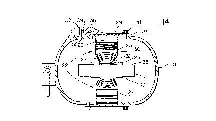
Referring to Fig. 2, the blade assembly has a snubber
damper set 22 which includes an upper snubber damper portion 23
and a lower snubber damper portion 24 which are located between
the spar surfaces 25 and 26 and the top and bottom surfaces of
the torque tube 10. The snubber damper set is of the elastomer
type and serves to support the torque tube in a proper relation-
ship with respect to the spar 7. The snubber damper set trans-
fers pitch control rod loads from the torque tube through the
snubbers and into the spar. The snubber damper set also controls
pitch flap coupling which occurs when the spar moves in a flap-
ping motion.
Each snubber-damper 23, 24 is preferably circular in cross-
section, and comprises a spherical elastomer bearing portion 27
SUBSTITUTE SHEET (RULE 26)
WO 9S/1~608 2 ~ 7 2 2 8 3 pCr/US9J/12057
,,,, , ,, - - , . ...
which is concentric about and supports the flexbeam 7 in posi-
tion. The outer portion of the snubber-damper is a flat elasto-
meric damper 28. Both portions consists of alternate elastomer
and non-extensible material laminates such that the end elastomer
laminates of flat elastomeric damper 28 are bonded to an end
plate 29 and race member 30, respectively, and the end elastomer
laminates of the spherical portion 27 are bonded to the race
member 30 and an inner support member 31, respectively~ This
bonding takes place during manufacture of each snubber-damper.
Referring to Fig. 3a, a lead/lag track error is illustrated,
for a four blade rotor la. Of course, the same concept can be
extended to rotors having other than four blades. As the blades
rotate under loaded conditions, minor differences in manufactur-
ing tolerances may result in a following blade 131 being at less
than or more than a right angle for a four bladed rotor to a
leading blade 32. This is illustrated by the phantom lines and
arrows. This change in blade spacing alters the weight distri-
bution of the assembly which may cause aircraft vibration. Of
course, a slight angular difference at the hub is magnified to a
large error at the blade tip.
Referring to Fig. 3b, a flap track error is illustrated.
Again, the four blade rotor la is shown, taken along line 3b-3b
of Fig. 3a. Preferably the blades move in a common plane 33.
However, due to differences in the stiffness of the damper compo-
nents supporting the blades, the blades may move off track (flap)in either an upper or lower direction relative to the rotor plane
SUBSTI~UTE SHEET (RULE 26) AI~IE~IDED S',~EFr
-
WO95/14608 21 7 2 2 g ~ PCT~S94/12057
causing a flapping error. This is illustrated by the phantom
lines and arrows. Such an error results in an unbalancing of the
rotor assembly which causes vibrations which are transmitted to
the aircraft.
Referring to Fig. 4, the torque tube 10 has the end plate 29
of a damper bolted to a top surface 34 thereof. The end plate of
the upper damper has a plurality of slotted holes 35 and has an
end lug 36. A lug 37 is located on the torque tube top surface
adjacent to the lug 36. A screw 38 extends between the lugs 36
and 37. The screw has lock nuts 39 associated with it for fixing
the spacing between the two lugs and thus the position of the
damper relative to the torque tube. The screw 38 operates in
conjunction with the slotted holes in the end plate to allow
adjusting the snubber position relative to an axis 40 of the
torque tube. Generally, an adjustment of +/- 1/2 degree should
be provided with this apparatus, to correct lead/lag errors,
though greater or lesser ranges of adjustment are possible.
Referring again to Fig. 2, a bolt 41 passes through the
slotted hole 35 to attach the end plate 29 to the torque tube 10.
To adjust a blade attached to the flexible spar 7, the bolts 41
are loosened and the spacing between the lugs 36 and 37 adjusted
using screw 38 to make the blade true with the axis of the spar
through the hub. Once the blade is adjusted to the proper
angular relationship with the hub, the screw is locked with the
nuts 39 and the bolts 41 are tightened to fix the blade in that
position.
SUBSTITUTE SHEET (RULE 26
WO95/14608 ~17 2 2 ~ 3 PCT~S94/12057
While a manual screw adjustment device is shown, it is
possible to utilize an actuator between the torque tube and end
plate to adjust the blade spacing remotely. For example, an
electrical, pneumatic or hydraulic actuator could be used to
dynamically adjust the blade spacing during rotation of the rotor
blades. These actuators could be computer controlled and respond
to position sensors mounted on the blades.
Referring to Fig. 5a, an adjustable damper set for reducing
damper stiffness variation is shown. The flexible æpar 7 is
located between an upper snubber damper 42 and a lower snubber
damper 43. The upper snubber damper has the end plate 44 for
attachment to the torque tube 10 by bolts 45. The lower snubber
damper also has an end plate 46 which is held by bolts 47 on the
torque tube 10. Each damper includes a plurality of elastomeric
plies 48 and a plurality of non-extensible shims 49, made of
metal or composite, located between the plies. Each damper also
has an enlarged shim, 49a and 49b respectively, located adjacent
to a respective end elastomeric ply, 48a and 48b respectively.
Ext~n~;ng portions 50a and 50b of each shim have through holes 51
for attachment of the shim by bolts 52 to the end plate, best
seen in Figs. 4 and 5b. Each end plate also includes corre-
sponding holes for allowing passage of the bolts 52 therethrough.
Thus, each snubber damper includes an end plate for attach-
ment to the torque tube and an extended shim which may be at-
tached to the end plate for removing the motion of the end
SUBSTITUTE SHEET ~RUEE 2~)
WO95/14608 ~ 7 2 2 g 3 PCT~S94112057
11elastomer ply from the damper to thereby increase the stiffness
of the assembly.
Preferably, each damper has an end laminate ply of desig-
nated stiffness, with the laminate ply of one damper preferably
being different in stiffness from the laminate ply of the other
damper. This can be accommodated by varying the thickness of the
plys, or by the choice of different elastomeric materials, i.e.
by substituting a synthetic rubber or silicon layer for a natural
rubber layer. For example, a relatively thin elastomer layer can
be incorporated in the upper damper to provide, for example, a 5
percent increase in stiffness if this elastomer layer were
functionally eliminated. For the lower snubber damper, a thicker
elastomer layer could be incorporated, with the removal of this
layer producing an approximate 8 percent increase in stiffness.
Each layer could be selected to provide a 2 to 10% stiffness
increase for a total range of 4 to 20% per set. Consequently, if
both layers were functionally eliminated, the damper assembly
would have an increased stiffness of about 13 percent.
Referring to Fig. 6a-d, the four different adjustment levels
for the damper are shown. In the first embodiment, neither of
the non-extensible shims is attached to an end plate and thus the
damper operates with all the elastomer plys and therefore it is
in its softest condition (Fig. 6a). If an increase in stiffness
is necessary, the upper shim is attached to the end plate and
thus the stiffness of the assembly is increased by 5 percent
(Fig. 6b). If this is considered inadequate, after testing or
SUBSTITUTE SHEET (RULE 26)
-
WO95/14608 ~ 228 ~ PCT~S9~/120S7
other evaluation, the bolts can be removed from the upper shim
and used instead to bolt the lower shim to the end plate thereby
creating an 8 percent increase in stiffness (Fig. 6c). If this
is still inadequate, bolts can be used to attach both the upper
and lower shims to the end plates, to produce a net increase of
13 percent in the stiffness of the assembly (Fig. 6d). Conse-
quently, each blade can be adjusted to eliminate or at least to
reduce the tracking error. Of course, these are illustrative
values, and other variations in the percentage increase in
stiffness can be accommodated according to the present invention.
Since the dampers may become softer with time in service,
this system allows post-operation adjustment to return each rotor
blade assembly to its initial stiffness, as an alternative to
replacing the dampers entirely.
Utilizing the apparatus of the present invention, the rotor
can be balanced to correct lead/lag and flap track errors through
adjustments in the position of the blades relative to the hub and
through the adjustment of the stiffness of the snubber dampers.
This minimizes vibration and also provides more effective air-
craft control, since such errors may inhibit effective transmis-
sion of pitch control changes to the blades.
While preferred embodiments of the present invention have
been shown and described, it will be understood by those skilled
in the art that various modifications and changes could be made
without varying from the scope of the present invention.
We claim:
SUB~TITUTE SHEET (RULE 2~)