Note: Descriptions are shown in the official language in which they were submitted.
-
~ WO 96/05438 2 ~ 7 2 2 9 2 PCT/CA95/00462
--1--
BLEED VALVE
Technical Field
The technical field to which this invention pertains is gas turbine
engines, particularly handling bleed valves for gas turbine engines.
Backqround of the Invention
In gas turbine engines for use in powering aircraft, air is
directed through multiple stage co"~pressors as it flows axially or
axially and radially through the engine to a combuster. As the air
passes through each s~lccessive co,npressor stage, the pressure of
the air is increased. Under certain conditions, such as when the
10 engine is operating at off design conditions, interstage bleed is
required to match the co,npressor stages. If this compressor matching
is not acheived an engine surge or blow-out may occur, endangering
the operation of the engine and the associ~ted aircraft.
To mitigate against these conditions, such gas turbine engines
15 have incorporated bleed valves in the engine casing forward of the
burner which, when an engine surge is imminent, open to rematch the
compressor stages. These bleed valves have taken many forms from
simple ports in the compressor casing which open via a movable valve
element to devices which separate ~dj~cent segments of the engine
20 casing thereby creating an opening there between.
However, these valves, although useful, present problems
where the air bleed off is directed into a secondary air flow, in lieu of
being dumped overboard. In the design of these prior art bleed valves
all of the criteria which must be met such as, simple maintenance of
25 the valve, maintenance of a smooth fluid flow through the bypass flow
path and quick response time are not all addressed in any single prior
art valve.
Therefore, what is necess~ry in this art is a bleed valve that is
simple to service, minimizes the disturbance to the secondary air flow
and offers quick response to the pressure changes which lead to the
engine operating problems.
CA 02172292 1998-08-24
Brief Description of the Invention
In accordance with the present invention there is provided a bleed valve for
use in a gas turbine engine, said engine having a bypass fluid flow path and a
primary fluid flow path downstream from an engine inlet of said engine, said
5 paths separated by a barrier and said bypass fluid flow path having an outer
perimeter, said bleed valve comprising; a housing positioned on said outer
perimeter of said bypass fluid flow path, and a piston having a first end which is
fitted into said housing, said piston extending across said bypass fluid flow
path; and said piston having a second end opposite said first end, said second
10 end sealably fitted into an opening in said barrier separating said primary fluid
flow path from said bypass fluid flow path; and wherein said piston is slidably
movable to open and close said opening in response to a pressure differential
between fluid pressures at two locations in said primary fluid flow path.
15 In accordance with another aspect of the present invention there is provided a
bleed valve for use in a bypass gas turbine engine, said engine having an
engine inlet, a first fluid flow path downstream from said engine inlet formed by
a compressor shroud positioned about one or more compressor stages through
which air from said engine inlet is compressed and directed to a burner section
20 of said engine where said compressed air is mixed with fuel and ignited, and a
second bypass fluid flow path downstream from said engine inlet formed by an
outer shroud of the engine and said compressor shroud through which bypass
air from said engine inlet is directed past said compressor shroud, said bleed
valve comprising; (a) a housing positioned within an opening within the outer
25 shroud, said housing forming a chamber, wherein said chamber is in flow
communication with said first fluid flow path at a first location; and (b) a piston
positioned to move within the chamber along a guide path, said guide path
extending from the outer shroud through the housing across the bypass flow
path to an opening in the compressor shroud which permits flow
30 communication between the first fluid flow path and the bypass flow path at a
CA 02172292 1998-08-24
-2a-
second location wherein said first location is downstream from said second
location in said first fluid flow path; (c) said piston having a first end moving
within the housing chamber and a second end positioned opposite the first
end, said second end formed to create a seal against the opening in the
5 compressor shroud; and (d) wherein the piston moves along said guide path
between an open position and a closed position thereby unsealing or sealing
the opening in the compressor shroud in response to the pressure differential
between the first and the second locations in the first fluid flow path.
10 In accordance with a further aspect of the present invention there is provided a
bleed valve for use in a bypass gas turbine engine, said engine having an
engine inlet, a first fluid flow path downstream from said engine inlet formed by
a compressor shroud positioned about one or more compressor stages through
which air from said engine inlet is compressed and directed to a burner section
15 of said engine where said compressed air is mixed with fuel and ignited, and a
second bypass fluid flow path downstream from said engine inlet formed by an
outer shroud of the engine and said compressor shroud through which bypass
air from said engine inlet is directed past said compressor shroud, said bleed
valve comprising; (a) a housing positioned within an opening within the outer
20 shroud, said housing forming a chamber, wherein said chamber is in flow
communication with said first fluid flow path at a first location; and (b) a piston
positioned to move within the chamber along a guide path, said guide path
extending from the outer shroud through the housing across the bypass flow
path to an opening in the compressor shroud which permits flow
25 communication between the first fluid flow path and the bypass flow path at asecond location wherein said first location is downstream from said second
location in said first fluid flow path; (c) said piston having a first end moving
within the housing chamber and a second end positioned opposite the first
end, said second end formed to create a seal against the opening in the
30 compressor shroud; (d) said piston, between said first and second ends, being
CA 02172292 1998-08-24
- 2b -
aerodynamically formed having a leading edge and a trailing edge, said
leading edge is facing upstream of said bypass flow path and being fitted into aslot in a strut member, said strut member having an upstream and a
downstream side, said slot being in said downstream side of said strut
5 member; and (e) wherein the piston moves along said guide path between an
open position and a closed position thereby unsealing or sealing the opening in
the compressor shroud in response to the pressure differential between the
first and the second locations in the first fluid flow path.
This invention will permit the use of a bypass valve which will respond to
prevent surges in the engine and will be easily serviced without disassembly of
the engine due to its positioning across the by pass flow path and having the
housing on the perimeter of the by pass flow path.
Brief Description of the Drawings
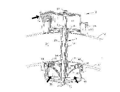
Figure 1 is a view of one embodiment of the valve of the present invention
indicating its location in a gas turbine engine.
Figure 2 is a breakaway view of one embodiment of the valve of the
present invention depicting the valve in the closed position.
Figure 3 is a breakaway view of one embodiment of the valve of the
present invention depicting the valve in the open position.
~5 Figure 4 is a cross sectional view of one embodiment of a valve of the
present invention positioned in a gas turbine engine in the open
position.
Figure 4A is a cross sectional view of the valve showing the pressure
control means.
-
~ WO 96/05438 2 1 7 2 ~ 9 2 PCT/CA95/00462
--3--
Figure 5 is a cross sectional view of one embodiment of a valve of
the present invention positioned in a gas turbine engine
in the closed position.
Figure 6 is a cross sectional view of taken along line 6~ of Figure
2 of the piston central portion and strut member.
Best Mode for Carryinq Out the Invention
The bleed valve of the present invention will be described
herein with reference to Figures ~. The description and the
drawings are intended to be exemplary and not limiting.
Rerer, iny now to the Figures in which the bleed valve of the
present invention is shown. The bleed valve 2 comprises a piston 4
having a first end 6 and a second end 8 connected by a center portion
10. The first end 6 is fitted into a chamber 12 inside a housing 14.
The housing 14 is fitted into an opening 16 in the outer perimeter of
15 the by bypass flow path, in this case the outer shroud 18 of the engine
20. The chamber 12 of the housing 14 is in flow or pressure
communication with one location within a primary flow path 22 of
compressed gas passing through the engine 20. Via an opening 24 in
the housing 14 a controlling pressure is introduced to schedule the
o valve opening.
In the present des~ iplion the housing 14 is formed of a single
unit which is attached to the outer shroud 18 by a number of bolts 26
and which is seated onto a flange 28 on the perimeter of the opening
16. The piston 4 is slidably mounted onto a rod or similar means 29
25 which passes longitudinally through sul ~s~ ,lially the center of the
piston 4.
The second end 8 is formed such that it will seat in and seal an
opening 30 in a barrier sepal-aling the bypass flow path 34 from the
primary flow path 22, in the present embodiment this is the inner
30 shroud 32, and thereby prevent any of the ~rir"aly fluid flow 22 to
pass to the bypass fluid flow path 34 through said opening 30 when
the piston 4 is in the closed position. This may be achieved in any
number of designs.
~ 1 7 2 2 9 2 PCT/CA9S/00462
WO 96/05438
--4--
The present embodiment depicts an aerodynamic design for the
second end 8 in which the top 35 of the second end 8 is sm ool h and
forms a smooth plane with the surface of the inner shroud 32 when the
valve 2 is in the closed position as shown in Figures 2 and 5.
However, that portion of the second end 8 which is below the inner
shroud 32 when the valve 2 is in the closed position, the bottom 36 of
the second end 8, is downwardly inwardly frustoconically tapered.
Although it is not necessary that the bottom 36 be formed in such a
manner, it is preferred that it be formed in such a shape so as to permit
an even transition zone for the fluid to flow from the primary flow path
22 into the bypass flow path 34, and to control the rate of opening and
closing of the valve.
In addition, a portion of the bottom 36 which is facing upstream
of the bypass fluid flow path 34, is in the form of an arcuate apron 38
extending around the leading edge 40 of the circumference 42 of the
second end 8, from about one side 44 of the second end 8 of the
piston to the opposite side 46 of the second end 8 of the piston and
crossing the plane perpendicular to the bypass flow path 34. The
apron 38 further extends from just under the top of the second end 8 to
just below the inner shroud 32 when the valve 2 is in the open position
(See Figure 3). This apron 38 prevents bleed flow exit in the upstream
direction of the by-pass flow. Such a flow will disturb the fan by
arrecli,)g its stability, reducing surge margin and increasing noise level.
As depicted in Figure 4 and 5 the opening 30 in the inner
shroud 32 houses the structural framework 48 to support the rod 29 on
which the piston 4 is slidably fitted. The rod 29 is removably
connected to the structural framework 48 by a nut 50 threaded onto
the end 52 of the rod 29 and the other end of the rod 29 is removably
~ixed in the same manner to an opening in the housing 14 by a nut 57.
~ushings 54 are introduced between the rod 29 and the piston 4 to
ensure free sliding movement of the piston 4. A col"pression spring
56 is fitted on to rod 29 at the end 52 between the structural framework
48 and piston end 8 to ensure that with no pressures acting on the
piston 4, the piston 4 will remain in a partly open condition. This valve
position will enhance engine starting.
2 1 7 ~ 2 9 ~ PCT/CAg510046~
WO 96/OS438
--5--
Additionally the upstream surface 58 of the piston having
central portion 10 may be fitted with a slot 60 which slides over a key
61 which is attached to housing 14. The upsl,ea", surface 58 of the
piston central portion 10 may be designed in the form of an
5 aerodynamic shape in combination with the strut 64 as shown in
Figure 6, thereby reducing the disturbance in the bypass flow path 34.
The key 61 and the slot 60 provide an cinlilola~ion means to ensure
alignment of the strut 64 and the piston central portion 10. This also
acts as an antirotation feature to insure alignment of the apron 38 and
lO piston central portion 10.
The bleed valve responds to a preset pressure differential
between a first location in the primary fluid flow path 22 and a second
location in the primary flow path 22 such that as the pressure in the
second location, which is in pressure communication with the chamber
12 in the housing 14 in which the first end 6 of the piston 4 is fitted, is
greater than the pressure at the first location, which is in pressure and
flow communication with the pri" ,ai y fluid flow path 22, the valve 4
remains in the closed position and none of the fluid of the ~rir"a",/ fluid
flow path 22 is permitted to pass from the ~, i" ,a, y fluid flow path 22 to
the bypass fluid flow path 34. However, in the event that the pressure
at the first location is greater than the second location by a
predetermined amount, then the pressure in the chamber 12 of the
housi~g 14 is less than that at the opening 30 of the inner shroud 32
and the piston 4 is slidably moved up the rod 29 thereby moving the
second end 8 of the piston 4 into a position where it no longer seals
the opening 30 in the inner shroud 32 and therebypermitting a portion
of the primary fluid flow 22 to pass through the opening 30 in the inner
shroud 32 to the bypass fluid flow path 34.
As may be seen by viewing Figure 4A the pressure from the first
location is upstream from the maximum co" ,~,ressor outlet for the
primary flow path 22, while the second location is downstream from the
maximum coi"pressor outlet and is in flow communication via a tube
(partially indicated at 66). The tube is fitted with an orifice 68 (this may
be an adjustible valve i.e. needle valve or a simple hole of a
~ 35 predetermined size) and connects with a second tube 70 forming a Tor Y having one end connected to the housing at opening 24 and the
other end 72 vented to alll~ospl ~ere through an orifice 73. In addition,
WO 96/05438 2 t 7 2 2 9 2 PCTICA95/00462
a regulating means 74 is fitted between the orifices 68 and 73 to
control the valve opening to a certain co",pressor speed. The
pressure created at opening 24 will be such that the valve will have a
predetermined position as a function of co",5~ressor rotational speed
5 thereby bleeding as required and hence preventing surge.
The present invention offers a bleed valve for use in bypass
engines having unique and beneficial advar,lages not seen in the prior
art. The present invention discloses a bleed valve which is releasably
mounted on the exterior of the engine to permit easy removal and
o maintenance without the disassembly of the engine as necessitated by
prior designs. In addition the valve offers a minimum disturbance to
the flow path of the bypass flow and therefore lessens any loss of
efficiency due to the placement of such a device across the flow path
of the bypass fluid.
While the particular invention has been described with
reference to illustrated embodiments this description is not meant to
be construed as limiting. It is understood that although the present
invention has been described in a prefer,ed embodiment various
modifications of the illustrated embodiments as well as additional
20 embodiments of the invention will be apparent to persons of ordinary
skill in this art without departing from the spirit of this invention. It is
therefore co"le,n~lated that the appended claims