Language selection

Search

Patent 2172707 Summary

Third-party information liability

Some of the information on this Web page has been provided by external sources. The Government of Canada is not responsible for the accuracy, reliability or currency of the information supplied by external sources. Users wishing to rely upon this information should consult directly with the source of the information. Content provided by external sources is not subject to official languages, privacy and accessibility requirements.

Claims and Abstract availability

Any discrepancies in the text and image of the Claims and Abstract are due to differing posting times. Text of the Claims and Abstract are posted:

  • At the time the application is open to public inspection;
  • At the time of issue of the patent (grant).
(12) Patent: (11) CA 2172707
(54) English Title: APPARATUS FOR CONTROLLING OPERATION OF A RAILCAR DISCHARGE GATE ASSEMBLY
(54) French Title: APPAREIL COMMANDANT LE FONCTIONNEMENT D'UN ENSEMBLE BARRIERE DE DECHARGE DE WAGON-TREMIE
Status: Expired and beyond the Period of Reversal
Bibliographic Data
(51) International Patent Classification (IPC):
  • B61D 7/26 (2006.01)
(72) Inventors :
  • DOHR, JEREMY J. (United States of America)
  • FISCHER, ROBERT T. (United States of America)
  • TOMS, ROBERT S. (United States of America)
(73) Owners :
  • MINER ENTERPRISES, INC.
(71) Applicants :
  • MINER ENTERPRISES, INC. (United States of America)
(74) Agent: MCCARTHY TETRAULT LLP
(74) Associate agent:
(45) Issued: 2001-02-20
(86) PCT Filing Date: 1994-06-09
(87) Open to Public Inspection: 1995-04-13
Examination requested: 1998-05-05
Availability of licence: N/A
Dedicated to the Public: N/A
(25) Language of filing: English

Patent Cooperation Treaty (PCT): Yes
(86) PCT Filing Number: PCT/US1994/006498
(87) International Publication Number: WO 1995009753
(85) National Entry: 1996-03-26

(30) Application Priority Data:
Application No. Country/Territory Date
08/130,250 (United States of America) 1993-10-01

Abstracts

English Abstract


An apparatus for controlling operation of a railcar discharge gate assembly including a frame (14) defining a discharge opening (16)
with a gate (18) slidably arranged on the frame (14) for movement along a predetermined path of travel between open and closed positions.
The apparatus of the present invention includes an operating shaft (34) rotatably supported on the frame (14) for selectively moving the gate
(18) between open and closed positions in response to rotation of the shaft (34). A lock assembly (36) is carried on the frame (14) and is
operably coupled to the operating shaft (34). The lock assembly (36) includes a displaceable stop member (50) which when the gate (18)
is closed, extends into the path of travel of the gate (18) to prevent movement of the gate (18) relative the frame (14), and which moves in
timed relation relative to movement of the gate (18) such that upon rotation of the operating shaft (34) to move the gate 118) to an open
position, the stop member (50) is automatically removed from the path of travel of the gate (18) prior to movement of the gate (18).


French Abstract

Appareil commandant le fonctionnement d'un ensemble barrière de décharge de wagon-trémie, et comprenant un châssis (14) définissant une ouverture de décharge (16), une barrière (18) étant disposée coulissante sur le châssis (14) afin de se déplacer le long d'une trajectoire prédéterminée entre des positions ouverte et fermée. L'appareil, selon la présente invention, comprend un axe d'actionnement (34) monté rotatif sur le châssis (14) afin de déplacer sélectivement la barrière (18) entre des positions ouverte et fermée en réponse à la rotation de l'axe (34). Un ensemble verrou (36), porté par le châssis (14), est accouplé de manière fonctionnelle à l'axe d'actionnement (34). Cet ensemble verrou (36) comprend une butée mobile (50) qui, lorsque la barrière (18) est fermée, s'étend dans la trajectoire de déplacement de la barrière (18) afin d'en empêcher le déplacement par rapport au châssis (14). La butée se déplace de manière synchronisée par rapport à la barrière (18) de sorte que, lors de la rotation de l'axe (34) permettent de déplacer la barrière (18) vers une position ouverte, la butée (50) est automatiquement éloignée de la trajectoire de la barrière (18) avant le déplacement de cette dernière (18).

Claims

Note: Claims are shown in the official language in which they were submitted.


WE CLAIM:
1. A gate control apparatus and railway hopper car discharge gate
assembly including a frame defining a generally rectangular discharge
opening with a generally rectangular discharge gate mounted on said frame
for movement between open and closed positions along a predetermined path
of travel, said apparatus comprising:
an operating shaft rotatably supported on said frame adjacent a rear
end of said gate, said operating shaft being connected to said gate whereby
said gate slidably moves forwardly and rearwardly between the open and
closed positions in response to rotation of said operating shaft;
a lock assembly carried on said frame and including a displaceable
stop member which, when said gate is in its closed position, extends into the
predetermined path of travel to positively engage an edge of said gate thereby
preventing movement of the gate relative to said frame; and
wherein a drive is provided between said lock assembly stop member
and said operating shaft for positively displacing said stop member from said
path of travel of said gate upon rotation of said operating shaft prior to
movement of the gate toward the open position.
2. The gate control apparatus and railway hopper car discharge gate
assembly according to claim 1 wherein said operating shaft is connected to
said gate through pinion gears arranged upon said operating shaft and which
intermesh with racks fitted to an underside of said gate.
3. The gate control apparatus and railway hopper car discharge gate
assembly according to claim 1 wherein said stop member is pivotally mounted
on said frame for vertical movement about a fixed generally horizontal axis
extending generally parallel to said operating shaft.
4. The gate control apparatus and railway hopper car discharge gate
assembly according to claim 1 wherein said drive includes a cam mounted on

said operating shaft for positively displacing said stop member from the path
of travel of said gate upon rotation of said operating shaft.
5. The gate control apparatus and railway hopper car discharge gate
assembly according to claim 1 wherein said stop member is resiliently urged
by a spring toward an engaging position with said gate.
6. The gate control apparatus and railway hopper car discharge gate
assembly according to claim 1 wherein said stop member is provided with a
counterweight for naturally causing said stop member to be urged toward
engagement with said gate.
7. The gate control apparatus and railway hopper car discharge gate
assembly according to claim 1 wherein said drive includes a lost motion
mechanism for permitting a predetermined range of free rotation of the
operating shaft prior to movement of said gate toward the open position.
8. A gate control apparatus and railway hopper car discharge gate
assembly including a frame defining a discharge opening with a discharge
gate slidably arranged on said frame for movement along a predetermined
plane of travel between open and closed positions, said apparatus comprising:
an operating shaft supported for rotation by said frame and operable
to selectively move the gate between the open and closed positions in
response to rotation of said shaft; and
a lock assembly carried on said frame and operably coupled to said
operating shaft, said lock assembly including a stop member which, when the
gate is in the closed position, extends into said plane of travel to prevent
movement of the gate relative to the frame, and wherein said stop member is
driven in timed relation relative to movement of said gate such that upon
rotation of said operating shaft to move said gate to the open position said
stop member is automatically removed from the plane of travel of the gate
prior to movement of the gate toward the open position.

9. The gate control apparatus and railway hopper car discharge gate
assembly according to claim 8 wherein said operating shaft is coupled to said
gate through a rack and pinion drive mechanism arranged beneath the
predetermined plane of travel of said gate.
10. The gate control apparatus and railway hopper car discharge gate
assembly according to claim 9 where a lost motion mechanism is provided
between said operating shaft and said rack and pinion drive mechanism for
permitting rotation of said operating shaft through a predetermined range of
rotation prior to imparting an opening movement to said gate.
11. The gate control apparatus and railway hopper car discharge gate
assembly according to claim 8 wherein said stop member is mounted on said
frame for generally vertical movement relative to the plane of travel of said
gate.
12. The gate control apparatus and railway hopper car discharge gate
assembly according to claim 8 wherein said stop member of said locking
assembly is biased into the plane of travel of said gate.
13. The gate control apparatus and railway hopper car discharge gate
assembly according to claim 8 further including an actuator rotatable with and
in response to rotation of said operating shaft for positively removing said
stop member from the plane of travel of the gate.
14. A gate control apparatus and railway car discharge gate assembly
including a frame defining a generally rectangular discharge opening with a
generally rectangular discharge gate mounted on said frame for movement
along a predetermined path of travel extending between a forward closed
position and a rearward open position, said apparatus comprising:
an operator controlled actuation assembly for moving said gate along
its predetermined path of travel between the open and closed positions, said
actuation assembly including an operating shaft mounted on said frame for

rotation about a fixed axis extending generally parallel to a rear edge of
said
gate and wherein said operating shaft is operably coupled to said gate;
a lock assembly carried on said frame, said lock assembly including
a stop member which, when said gate is in its forward closed position, is
positioned to wedge against an edge of the gate thereby preventing movement
of the gate relative to the frame and which is displaceable to a released
position to permit said gate to move relative to said frame toward the open
position; and
wherein a drive including a lost motion mechanism is arranged
between said operating shaft and said stop member for automatically
effecting, in sequential order and in response to rotation of said operating
shaft, displacement of said stop member from the path of travel of said gate
and movement of said gate toward the open position.
15. The gate control apparatus and railway hopper car discharge gate
assembly according to claim 14 wherein said actuation assembly further
includes a rack and pinion drive assembly comprised of a pair of laterally
spaced pinion gears mounted on said operating shaft for engagement with a
pair of laterally spaced racks fixed to an undersurface of said gate.
16. The gate control apparatus and railway hopper car discharge gate
assembly according to claim 14 wherein said stop member of said lock
assembly includes a lever pivotally mounted on the frame for rocking
movement about an axis extending generally parallel to said operating shaft,
with one end of said lever being adapted to positively engage and wedge
against said gate edge.
17. The gate control apparatus and railway hopper car discharge gate
assembly according to claim 16 wherein said lock assembly further includes
a spring member for resiliently urging said lever into engagement with said
gate.

18. The gate control apparatus and railway hopper car discharge gate
assembly according to claim 16 wherein said drive further includes a cam
mounted on and for rotation with said operating shaft for engaging said lever
in a manner positively displacing the lever to a released position in response
to rotation of said operating shaft.
19. The gate control apparatus and railway hopper car discharge gate
assembly according to claim 14 wherein said operating shaft is operably
coupled to said gate through a rack and pinion assembly, and wherein said
lost motion mechanism includes a specifically configured slot defined by
pinions of said rack and pinion assembly for allowing said operating shaft to
rotate through a predetermined angle of rotation prior to imparting motion to
said pinions and thereby movement of the gate.
20. The gate control apparatus and railway hopper car discharge gate
assembly according to claim 19 wherein said lost motion mechanism
incorporates a dwell period during which a cam member carried on the
operating shaft is rotated into engagement with the stop member and an
actuating period during which the cam member is rotated to positively move
the stop member to a released position prior to movement of the gate toward
the open position.
21. A gate control apparatus and railway hopper car discharge gate
assembly including a frame defining a generally rectangular discharge
opening with a generally rectangular discharge gate mounted on said frame
for movement between open and closed positions along a predetermined path
of travel, said apparatus comprising:
an operating shaft rotatably supported on said frame adjacent an end
of said opening, said operating shaft being connected to said gate whereby
said gate slidably moves between the open and closed positions in response
to rotation of said operating shaft;

a lock assembly including a displaceable stop member which, when
said gate is in its closed position, prevents movement of the gate relative to
said frame; and
wherein a drive is provided between said lock assembly stop member
and said operating shaft for positively displacing said stop member prior to
movement of the gate.
22. The gate control apparatus and railway hopper car discharge gate
assembly according to claim 21 wherein said operating shaft is connected to
said gate through pinion gears arranged upon said operating shaft and which
intermesh with racks fitted to an underside of said gate.
23. The gate control apparatus and railway hopper car discharge gate
assembly according to claim 21 wherein said stop member is pivotally
mounted for vertical movement about a fixed generally horizontal axis
extending generally parallel to said operating shaft.
24. The gate control apparatus and railway hopper car discharge gate
assembly according to claim 21 wherein said drive includes a cam mounted
on said operating shaft for positively displacing said stop member upon
rotation of said operating shaft.
25. The gate control apparatus and railway hopper car discharge gate
assembly according to claim 21 wherein said lock assembly further comprises
a spring for resiliently urging said stop member into a position to prevent
movement of said gate.
26. The gate control apparatus and railway hopper car discharge gate
assembly according to claim 21 wherein said drive includes a lost motion
mechanism for permitting a predetermined range of free rotation of the
operating shaft prior to movement of said gate.

27. A gate control apparatus and railway hopper car discharge gate
assembly including a frame defining a discharge opening with a discharge
gate slidably arranged on said frame for movement along a predetermined
plane of travel between open and closed positions, said apparatus comprising:
an operating shaft supported for rotation by said frame and operable
to selectively move the gate between the open and closed positions in
response to rotation of said shaft; and
a lock assembly operably coupled to said operating shaft, said lock
assembly including a stop member which, when the gate is in the closed
position, prevents movement of the gate relative to the frame, and wherein
said stop member is driven in timed relation relative to movement of said
gate such that upon rotation of said operating shaft to move said gate to the
open position said stop member is automatically displaced from the plane of
travel of the gate prior to movement of the gate.
28. The gate control apparatus and railway hopper car discharge gate
assembly according to claim 27 wherein said operating shaft is coupled to
said gate through a rack and pinion drive mechanism arranged beneath the
predetermined plane of travel of said gate.
29. The gate control apparatus and railway hopper car discharge gate
assembly according to claim 28 where a lost motion mechanism is provided
between said operating shaft and said rack and pinion drive mechanism for
permitting rotation of said operating shaft through a predetermined range of
rotation prior to imparting an opening movement to said gate.
30. The gate control apparatus and railway hopper car discharge gate
assembly according to claim 27 wherein said stop member is mounted for
generally vertical movement.
31. The gate control apparatus and railway hopper car discharge gate
assembly according to claim 27 wherein said lock assembly further includes

a spring for resiliently urging said stop member into a position to prevent
movement of said gate.
32. The gate control apparatus and railway hopper car discharge gate
assembly according to claim 27 further including an actuator rotatable with
and in response to rotation of said operating shaft for effecting automatic
displacement of the stop member prior to movement of the gate.
33. A gate control apparatus and railway hopper car discharge gate
assembly including a frame defining a generally rectangular discharge
opening with a generally rectangular discharge opening with a generally
rectangular discharge gate mounted on said frame for movement along a
predetermined path of travel extending between a closed position and an open
position, said apparatus comprising:
an operator controlled actuation assembly for moving said gate along
its predetermined path of travel between the open and closed positions, said
actuation assembly including an operating shaft mounted on said frame for
rotation about a fixed axis extending generally parallel to an edge of said
gate
and wherein said operating shaft is operably coupled to said gate;
a lock assembly including a stop member which, when said gate is in
its closed position, is positioned to prevent movement of the gate relative to
the frame and which is displaceable to a released position to permit said gate
to move relative to said frame toward the open position; and
wherein a drive including a lost motion mechanism is arranged
between said operating shaft and said stop member for automatically
effecting, in sequential order and in response to rotation of said operating
shaft, displacement of said stop member and movement of said gate.
34. The gate control apparatus and railway hopper car discharge gate
assembly according to claim 33 wherein said actuation assembly further
includes a rack and pinion drive assembly comprised of a pair of laterally
spaced pinion gears mounted on said operating shaft for engagement with a
pair of laterally spaced racks operably fixed to an undersurface of said gate.

35. The gate control apparatus and railway hopper car discharge gate
assembly according to claim 33 wherein said stop member of said lock
assembly includes a lever pivotally mounted for rocking movement about an
axis extending generally parallel to said operating shaft.
36. The gate control apparatus and railway hopper car discharge gate
assembly according to claim 35 wherein said lock assembly further includes
a spring for resiliently urging said lever into a position to prevent movement
of said gate.
37. The gate control apparatus and railway hopper car discharge gate
assembly according to claim 35 wherein said drive further includes a cam
mounted on and for rotation with said operating shaft for engaging said lever
in a manner positively displacing the lever to a released position in response
to rotation of said operating shaft.
38. The gate control apparatus and railway hopper car discharge gate
assembly according to claim 33 wherein said operating shaft is operably
coupled to said gate through a rack and pinion assembly, and wherein said
lost motion mechanism includes a specifically configured slot defined by
pinions of said rack and pinion assembly for allowing said operating shaft to
rotate through a predetermined angle of rotation prior to imparting motion to
said pinions and thereby movement of the gate.
39. The gate control apparatus and railway hopper car discharge gate
assembly according to claim 38 wherein said lost motion mechanism
incorporates a dwell period during which a cam member carried on the
operating shaft is rotated into engagement with the stop member and an
actuating period during which the cam member is rotated to positively move
the stop member to a released position prior to movement of the gate.
40. A gate control apparatus and railway hopper car discharge gate
assembly including a frame defining a generally rectangular discharge

opening with a generally rectangular discharge gate mounted on said frame
for movement between open and closed positions along a predetermined path
of travel, said apparatus comprising:
an operating shaft assembly rotatably supported on said frame adjacent
an end of said opening, said operating shaft assembly being connected to said
gate whereby said gate slidably moves between the open and closed positions
in response to rotation of said operating shaft assembly, said operating shaft
assembly including capstans at opposite ends of a shaft;
a lock assembly carried on said frame and including a displaceable
stop member which, when said gate is in its closed position, extends into the
predetermined path of travel to positively engage an edge of said gate thereby
preventing movement of the gate relative to said frame; and
wherein a drive is provided between said lock assembly stop member
and said operating shaft assembly for positively displacing said stop member
from said path of travel of said gate upon rotation of one of said capstans of
said operating shaft assembly prior to movement of the gate toward the open
position.
41. The gate control apparatus and railway hopper car discharge gate
assembly according to claim 40 wherein said operating shaft assembly is
connected to said gate through pinion gears arranged upon said operating
shaft assembly and which intermesh with racks fitted to an underside of said
gate.
42. The gate control apparatus and railway hopper car discharge gate
assembly according to claim 40 wherein said stop member is pivotally
mounted on said frame for vertical movement about a fixed generally
horizontal axis extending generally parallel to said operating shaft assembly.
43. The gate control apparatus and railway hopper car discharge gate
assembly according to claim 40 wherein said drive includes a cam mounted
on said operating shaft assembly for positively displacing said stop member

from the path of travel of said gate upon rotation of a portion of said
operating shaft.
44. The gate control apparatus and railway hopper car discharge gate
assembly according to claim 40 wherein said stop member is resiliently urged
by a spring toward an engaging position with said gate.
45. The gate control apparatus and railway hopper car discharge gate
assembly according to claim 40 wherein said drive includes a lost motion
mechanism for permitting a predetermined range of free rotation of one of
said capstans of the operating shaft assembly prior to movement of said gate
toward the open position.
46. A gate control apparatus and railway hopper car discharge gate
assembly including a frame defining a discharge opening with a discharge
gate slidably arranged on said frame for movement along a predetermined
plane of travel between open and closed positions, said apparatus comprising:
an operating shaft assembly supported for rotation by said frame and
operable to selectively move the gate between the open and closed positions
in response to rotation of said operating shaft assembly, said operating shaft
assembly including capstans at opposite ends of a shaft; and
a lock assembly carried on said frame and operably coupled to said
operating shaft assembly, said lock assembly including a stop member which
when the gate is in its closed position, extends into said plane of travel to
prevent movement of the gate relative to the frame, and wherein said stop
member is driven in timed relation relative to movement of said gate such
that upon rotation of one of said capstans of said operating shaft assembly to
move said gate to the open position said stop member is automatically
removed from the plane of travel of the gate prior to movement of the gate
toward the open position.
47. The gate control apparatus and railway hopper car discharge gate
assembly according to claim 46 wherein said operating shaft assembly is

coupled to said gate through a rack and pinion drive mechanism arranged
beneath the predetermined plane of travel of said gate.
48. The gate control apparatus and railway hopper car discharge gate
assembly according to claim 47 where a lost motion mechanism is provided
between said operating shaft assembly and said rack and pinion drive
mechanism for permitting rotation of one of said capstans of said operating
shaft assembly through a predetermined range of rotation prior to imparting
an opening movement to said gate.
49. The gate control apparatus and railway hopper car discharge gate
assembly according to claim 46 wherein said stop member is mounted on
said frame for generally vertical movement relative to the plane of travel of
said gate.
50. The gate control apparatus and railway hopper car discharge gate
assembly according to claim 46 wherein said stop member of said locking
assembly is biased into the plane of travel of said gate.
51. The gate control apparatus and railway hopper car discharge gate
assembly according to claim 46 further including an actuator rotata.ble with
and in response to rotation of a portion of said operating shaft assembly for
positively removing said stop member from the plane of movement of the
gate.
52. The gate control apparatus and railway hopper car discharge gate
assembly including a frame defining a generally rectangular discharge
opening with a generally rectangular discharge gate mounted on said frame
for movement along a predetermined path of travel extending between a
closed position and an open position, said apparatus comprising:
an operator controlled actuation assembly for moving said gate along
its predetermined path of travel between the open and closed positions, said

actuation assembly including an operating shaft and capstans connected to
opposite ends of the operating shaft for rotation about a fixed axis extending
generally parallel to an edge of said gate and wherein said actuation assembly
is operably coupled to said gate;
a lock assembly carried on said frame, said lock assembly including
a stop member which, when said gate is in the closed position, is positioned
to wedge against an edge of the gate thereby preventing movement of the gate
relative to the frame and which is displaceable to a released position to
permit
said gate to move relative to said frame toward the open position; and
wherein a drive including a lost motion mechanism is arranged
between said actuation assembly and said stop member for automatically
effecting in sequential order and in response to rotation of one of said
capstans of said actuation assembly, displacement of said stop member from
the path of travel of said gate and movement of said gate toward the open
position.
53. The gate control apparatus and railway hopper car discharge gate
assembly according to claim 52 wherein said actuation assembly further
includes a rack and pinion drive assembly comprised of a pair of laterally
spaced pinion gears mounted on said operating shaft for engagement with a
pair of laterally spaced racks operably fixed to an undersurface of said gate.
54. The gate control apparatus and railway hopper car discharge gate
assembly according to claim 52 wherein said stop member of said lock
assembly includes a lever pivotally mounted on the frame for rocking
movement about an axis extending generally parallel to said operating shaft,
with one end of said lever being adapted to positively engage and wedge
against said gate edge.
55. The gate control apparatus and railway hopper car discharge gate
assembly according to claim 54 wherein said lock assembly further includes

a spring member for resiliently urging said lever into engagement with said
gate.
56. The gate control apparatus and railway hopper car discharge gate
assembly according to claim 54 wherein said drive further includes a cam
mounted on and for rotation with said operating shaft for engaging said lever
in a manner positively displacing the lever to a released position in response
to rotation of a portion of said actuation assembly.
57. The gate control apparatus and railway hopper car discharge gate
assembly according to claim 52 wherein said operating shaft is operably
coupled to said gate through a rack and pinion assembly, and wherein said
lost motion mechanism includes a specifically configured slot defined by
pinions of said rack and pinion assembly for allowing one of said capstans
of said actuation assembly to rotate through a predetermined angle of
rotation prior to imparting motion to said pinions and thereby movement of
the gate.
58. The gate control apparatus and railway hopper car discharge gate
assembly according to claim 57 wherein said lost motion mechanism
incorporates a dwell period during which a cam member carried on the
operating shaft is rotated into engagement with the stop member and an
actuating period during which the cam member is rotated to positively move
the stop member to a released position prior to movement of the gate toward
the open position.
59. A gate control apparatus and railway hopper car discharge gate
assembly including a frame defining a generally rectangular discharge
opening with a generally rectangular discharge gate mounted on said frame
for movement between open and closed positions along a predetermined path
of travel, said apparatus comprising:

an operating shaft assembly rotatably supported on said frame adjacent
an end of said opening, said operating shaft assembly being connected to said
gate whereby said gate slidably moves between the open and closed positions
in response to rotation of said operating shaft assembly, said operating shaft
assembly including capstans at opposite ends of a shaft;
a lock assembly including a displaceable stop member which, when
said gate is in its closed position, prevents movement of the gate relative to
said frame; and
wherein a drive is provided between said lock assembly stop member
and said operating shaft assembly for positively displacing said stop member
prior to movement of the gate.
60. The gate control apparatus and railway hopper car discharge gate
assembly according to claim 59 wherein said operating shaft assembly is
connected to said gate through pinion gears arranged upon said operating
shaft assembly and which intermesh with racks fitted to an underside of said
gate.
61. The gate control apparatus and railway hopper car discharge gate
assembly according to claim 59 wherein said stop member is pivotally
mounted for vertical movement about a fixed generally horizontal axis
extending generally parallel to said operating shaft assembly.
62. The gate control apparatus and railway hopper car discharge gate
assembly according to claim 59 wherein said drive includes a cam mounted
on said operating shaft assembly for positively displacing said stop member
upon rotation of said operating shaft assembly.
63. The gate control apparatus and railway hopper car discharge gate
assembly according to claim 59 wherein said lock assembly further
comprises a spring for resiliently urging said stop member into a position to
prevent movement of said gate.

64. The gate control apparatus and railway hopper car discharge gate
assembly according to claim 59 wherein said drive includes a lost motion
mechanism for permitting a predetermined range of free rotation of one of
said capstans of the operating shaft assembly prior to movement of said gate.
65. A gate control apparatus and railway hopper car discharge gate
assembly including a frame defining a discharge opening with a discharge
gate slidably arranged on said frame for movement along a predetermined
plane of travel between open and closed positions, said apparatus
comprising:
an operating shaft assembly supported for rotation by said frame and
operable to selectively move the gate between the open and closed positions
in response to rotation of said operating shaft assembly, said operating shaft
assembly including capstans at opposite ends of a shaft; and
a lock assembly operably coupled to said operating shaft assembly,
said lock assembly including a stop member which, when the gate is in the
closed position, prevents movement of the gate relative to the frame, and
wherein said stop member is driven in timed relation relative to movement
of said gate such that upon rotation of one of said capstans of said operating
shaft assembly to move said gate to the open position said stop member is
automatically displaced from the plane of travel of the gate prior to
movement of the gate.
66. The gate control apparatus and railway hopper car discharge gate
assembly according to claim 65 wherein said operating shaft assembly is
coupled to said gate through a rack and pinion drive mechanism arranged
beneath the predetermined plane of travel of said gate.
67. The gate control apparatus and railway hopper car discharge gate
assembly according to claim 65 wherein a lost motion mechanism is provided
between said operating shaft assembly and said rack and pinion drive
mechanism for permitting rotation of one of said capstans of said operating

shaft assembly through a predetermined range of rotation prior to imparting
an opening movement to said gate.
68. The gate control apparatus and railway hopper car discharge gate
assembly according to claim 65 wherein said stop member is mounted for
generally vertical movement.
69. The gate control apparatus and railway hopper car discharge gate
assembly according to claim 65 wherein said lock assembly further includes
a spring for resiliently urging said stop member into a position to prevent
movement of said gate.
70. The gate control apparatus and railway hopper car discharge gate
assembly according to claim 65 further including an actuator rotatably with
and in response to rotation of said operating shaft assembly for effecting
automatic displacement of the stop member prior to movement of the gate.
71. A gate control apparatus and railway hopper car discharge gate
assembly including a frame defining a generally rectangular discharge
opening with a generally rectangular discharge gate mounted on said frame
for movement along a predtermined path of travel extending between a
closed position and an open position, said apparatus comprising:
an operator controlled actuation assembly for moving said gate along
its predetermined path of travel between the open and closed positions, said
actuation assembly including an operating shaft and capstans connected to
opposite ends of the operating shaft for rotation about a fixed axis extending
generally parallel to an edge of said gate and wherein said actuation assembly
is operably coupled to said gate;
a lock assembly including a stop member which, when said gate is in
its closed position, is positioned to prevent movement of the gate relative to
the frame and which is displaceable to a released position to permit said gate
to move relative to said frame toward the open position; and

wherein a drive including a lost motion mechanism is arranged
between said actuation assembly and said stop member for automatically
effecting, in sequential order and in response to rotation of one of said
capstans of said actuation assembly, displacement of said stop member and
movement of said gate.
72. The gate control apparatus and railway hopper car discharge gate
assembly according to claim 71 wherein said actuation assembly further
includes a rack and pinion drive assembly comprised of a pair of laterally
spaced pinion gears mounted on said operating shaft for engagement with a
pair of laterally spaced racks operably fixed to an undersurface of said gate.
73. The gate control apparatus and railway hopper car discharge gate
assembly according to claim 71 wherein said stop member of said lock
assembly includes a lever pivotally mounted for rocking movement about an
axis extending generally parallel to said operating shaft.
74. The gate control apparatus and railway hopper car discharge gate
assembly according to claim 73 wherein said lock assembly further includes
a spring for resiliently urging said lever into a position to prevent movement
of said gate.
75. The gate control apparatus and railway hopper car discharge gate
assembly according to claim 73 wherein said drive further includes a cam
mounted on and for rotation with said operating shaft for engaging said lever
in a manner positively displacing the lever to a released position in response
to rotation of said actuation assembly.
76. The gate control apparatus and railway hopper car discharge gate
assembly according to claim 71 wherein said operating shaft is operably
coupled to said gate through a rack and pinion assembly, and wherein said
lost motion mechanism includes a specifically configured slot defined by

pinions of said rack and pinion assembly for allowing one of said capstans
of said actuation assembly to rotate through a predetermined angle of
rotation prior to imparting motion to said pinions and thereby movement of
the gate.
77. The gate control apparatus and railway hopper car discharge gate
assembly according to claim 75 wherein said lost motion mechanism
incorporates a dwell period during which a cam member carried on the
operating shaft is rotated into engagement with the stop member and an
actuating period during which the cam member is rotated to positively move
the stop member to a released position prior to movement of the gate.

Description

Note: Descriptions are shown in the official language in which they were submitted.


~ wo ss/os7s3 ~ 1 7 210 7 PCT/US94/06498
APPARATUS FOR CONTROLLING OPERATION
OF A RAILCAR DISCHARGE GATE ASSEl\~BLY
FIELD OF THE INVENTION
The present invention generally relates to discharge gate assemblies for railway hopper
cars and, more particularly, to an a~paralus for controlling operation of a discharge gate
assembly between open and closed positions.
BACKGROUND OF THE INVENTION
Railway hopper cars typically include one or more discharge openings through which
lading within the car is adapted to be discharged by gravity. A discharge gate assembly
including a frame is fitted to the hopper car and defines a discharge opening through which
the lading within the car is exh~ te~ A gate is slidably mounted on the frame for
movement between open and closed positions to control the discharge of the lading from the
hopper car. The gate is typically moved between positions through a rack and pinion system,
including two rows of racks welded to an underside of the gate and two pinions which are
arranged on a rotatable operating shaft rotatably mounted on the frame of the gate assembly.
As will be appreciated, it is important to plev~nL inadvellel,L opening of the gate.
Railway cars are subjected, however, to numerous impact forces, some of which can be quite
severe. When a railway car moves down a hump in a classification yard, it likely will impact
with other cars on the same track. A filled railway car weighs several tons and has a
tendency to gather substantial momentum as it moves along the track. Thus, the impact with
a stationary railway car to which it is to be coupled can be exreetlingly forceful. While
shock absorbers are built into the coupling units on the cars, severe shock loads remain
within the body of the car and its contents. Such shock loads can affect the position of the

wo 95/09753 ~ 7 ~7 PCT/US94/06498
gate. Of course, if a partially opened gate is not recognized, a substantial amount of lading
can gravitationally pass through the gate as the cars move from one shipping location to
another.
Accordingly, each gate assembly is typically provided with some form of locking
mech~ni.cm for holding the gate in a closed position. The heretofore known locking
mrr.h~ni.~m.~ for holding the gate closed have a myriad of designs. R~ic.~lly, however, such
locking mech~ni~m~ include some form of m~ch~nir.~l Iocking members which are effective
to lock the gate in a closed position, but they require both manual opening and manual
closing to be effective.
For several reasons, the heretofore known m~ml~lly operated locking mech~ni~m.c are
constantly being destroyed when the gates are opened. The opel~t~lg condition of the locking
mech~ni~m is often overlooked when lading is to be discharged from the hopper car. T imitecl
visual access, inconvenient physical access, human error and the increasing rlem~ntl to
quickly unload the rail cars all contribute to the m~ml~lly operated locking mech~ni~m.c being
either substantially damaged or completely destroyed. Moreover, high-powered torque
drivers are often used to open the gates and result in inad\,~lLellL destruction of the locking
mech~ni~m~ .
Thus, there is a need and a desire for a rail car discharge gate assembly including a
lock mechanism which securely m~int~in~ the gate in a closed position even under severe
impact loading conditions and yet which opens autom~tir~lly to avoid damage and destruction
of the lock mech~ni.cm.

wo 95/097S3 2 1 7 2 7 O ~ PCT/U$94106498
SUM~ARY OF THE INVENTION
In view of the above, and in accordance with the present invention, there is provided
an a~araLus for controlling operation of a railway car discharge gate assembly including a
frame defining a discharge opening with a discharge gate slidably arranged on the frame.
The al~al~Lus of the present invention includes an operating shaft supported onthe frame for
selectively moving the gate between open and closed positions in response to rotation of the
shaft. A lock assembly is carried on the frame and is operably coupled to the opel~Lillg
shaft. The lock assembly includes a displacable stop member which, when the gate is in its
closed position, extends into the path of travel of the gate to pl~vellL movement of the gate
relative to the frame, and which is driven in timed relation relative to movement of the gate
such that upon rotation of the operating shaft to move the gate to an open position the stop
member is autom~tir~lly removed from the path of movement of the gate prior to movement
of the gate toward its open position.
In a ~ler~ ,d form of the invention, the ~elaLillg shaft is operably coupled to the
gate through a rack and pinion drive mech~ni.~m The drive mechanism includes a pair of
laterally spaced pinion gears mounted on the operating shaft and which engage laterally
spaced rows of racks welded or otherwise affixed to an underside of the gate.
The stop member of the lock assembly is mounted on the frame for generally vertical
movement into and out of t_e path of travel of t_e gate. In the most pler.,lled form of the
invention, t_e stop member is pivotally mounted for movement about an axis ex~n-ling
generally parallel to the axis of rotation of the operating shaft. When the gate is in a closed
position, the stop member is urged into wedging relation with an edge of the gate thereby
plevellLillg displacement of the gate relative to the frame.

wo 95/09753 ~ ~ ~ 2 7 ~ 7 PCT/US94/06498
The stop member of the lock assembly is biased into engagement with the gate thus
inhibiting inadvertent movement of the stop member upon impact loading of the rail car. In
one form of the invention, a spring re~iliently urges the stop member into the path of
movement of and preferably into engagement with the gate. In an alternative embodiment,
the stop member is configured with a coullL~ ight for naturally causing the stop member
to be urged toward eng~gem~n~ with the gate.
The present invention further includes a drive which is responsive to rotation of the
operating shaft for positively removing the stop member from the path of movement of the
gate. In a preferred form of the invention, the drive includes an actuator mounted on the
operating shaft for positively displacing the stop member from the path of travel of the gate
upon rotation of the operaLillg shaft. In a most pler~"~d form of the invention, the actuator
includes a cam having a series of lobes peripherally arranged thereabout.
A salient feature of the present invention concerns the ability to autom~ti~lly remove
the stop member of the lock assembly from the path of movement of the gate prior to
movement of the gate toward its open position. To accomplish these ends, the drive includes
a lost motion m~ch~nicm interposed between the operating shaft and the stop member for
autom~tic~lly effecting in sequential order and in response to rotation of the operating shaft
displacement of the stop member from the path of gate travel followed by rnovement of the
gate toward an open position. In a most pler~ d form of the invention, the lost motion
mech~ni~m permits the operating shaft to be rotated through a predetermin~cl angle of free
rotation without causing linear displacement of the door toward its open position. The lost
motion mech~ni~m preferably incorporates a delay before the pinions are coupled to the shaft
while allowing the stop member to be immP~ tely responsive to rotation of the shaft.

wo 9~/09753 2 i ~ 2 7 0 7 PCT/US94/06498
Preferably, an initial dwell embodied in the lost motion mech~ni~m prevents rack and pinion
backlash from prematurely diseng~ing the stop member of the lock assembly.
A major advantage of the present invention involves its simplistic operation. The stop
member of the lock assembly is biased into the path of movement of the gate thereby
preventing inadvelL~llL displ~ nt of the gate relative to the frame and thus ensuring that
the gate is m~int~inP~ in a closed position noLwi~ iL~ ing the impact loads which tend to
urge the gate toward an open position. When the operating shaft is purposefully rotated to
open the gate, the stop member of the lock assembly is autom~tir~lly displaced prior to
movement of the gate. After the operating shaft is rotated through a predetermined angle of
rotation, the gate is moved toward an open position without concern for damage to the lock
assembly. Upon return of the gate to the closed position, the stop member of the lock
assembly is autom~tir~lly retmn~ to a position wherein it lies in the path of movement of
the gate thereby ~l~vellLing inadv~lLellL displacement of the gate.
Numerous other features and advantages of the present invention will be come readily
apparent from the following detailed description, the accompanying drawings, and the
appended claims.
BRIEF DESCRIPTION OF THE DRAWINGS
FIGURE 1 is a rear elevational view of a railway hopper car discharge gate assembly
embodying features of the present invention;
FIGURE 2 is a side elevational view of the discharge gate assembly illustrated in
FIGURE l;
FIGURE 3 is a sectional view taken along line 3-3 of FIGURE l;

WO 95/09753 PCT/US94tO6498
~172707
FIGURE 4 is an enlarged fr~gment~ry plan view of a lock assembly associated with
the present invention;
FIGURE 5 is a sectional view taken along line 5-5 of FIGURE 3 in showing the lock
assembly in a locked position;
FIGURE 6 is a view similar to FIGURE 5 showing the lock assembly of the present
invention in a released position;
FIGURE 7 is a s~h~m~tic elevational view of a pinion gear forming part of the present
invention; and
FIGURE 8 is a view similar to FIGURE 5 but showing an alL~ Liv~ embodiment of
a lock assembly according to the present invention.
DETAILED DESCRIPIION OF THE INVENTION
While the present invention is susceptible of embotlim~nt~ in various forms, there is
shown in the drawings two plefelled embo~1i",r"l~ hereinafter described with the
underst~n-ling that the present disclosure is to be considered as exemplifications of the
invention, and are not intended to limit the invention to the specific embo~im~nt~ illustrated.
Referring now to the drawings, wherein like l~r~.ellce numerals refer to like parts
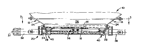
throughout the several views, there is schem~tir~lly illustrated in FIGURES 1 and 2 a railway
car hopper outlet generally in~lic~tetl by reference numeral 10. It will be understood by those
skilled in the art that a railway hopper car may have more than one outlet provided thereon.
Since the outlets are substantially similar, however, only one outlet is shown for purposes of
this description. Suffice it to say, the outlet 10 is arranged at the lower end of a conventional
hopper section of a railroad hopper car.

wo 95/09753 2 ~. 7 2 7 0 7 PCT~US94/06498
To control the discharge of lading from the outlet 10, a discharge gate assembly 12
is arrange~ in combination with each outlet. The gate assembly 12 includes a frame 14
defining a discharge opening 16 with a door or gate 18 mounted on the frame 14 for
movement between open and closed positions. Operation of the gate 18is controlled by an
a~alalus 20 which is the subject of this invention.
As shown in FIGURE 3, frame 14 preferably has a rectangular configuration including
a front frame section 22, side frame sections 24, and a rear frame section 26. In the
ctr~t~l1 embotlim~nt~ the sections 22, 24 and 26 of frame 14 define coplanar channels (not
shown) which slidably accommodate peripheral edges of the gate 18 and define a path of
travel for the gate between open and closed positions thereof. In the illll~tr~t~1 embo-1im~nt
the gate 18 has a generally horizontal and rectangular configuration which is slidable across
the discharge opening 16 to close same and is movable to a second or open position away
from the discharge opening 16.
Projecting away from the side frame sections 24 in parallel relation are e~t~n~ion
assemblies 28 which support the gate 18 when it is moved to an opened position. The rear
ends of the extension assemblies 28 are preferably interconn~ct~-l by a suitable transverse
support 30.
Returning to FIGURES 1 and 2, the a~pardLus 20 for controlling operation of the
gate 18 between open and closed position generally includes an operating shaft 34 and a lock
assembly 36 operably coupled to the operating shaft 34. In the illustrated embodiment, the
dLillg shaft 34 transversely extends across a rear end of and beneath the gate 18. The
operating shaft is rotatable about a fixed axis 37 and is supported on opposite sides by the

;~ ~ 7 ~ 7 ~ ~ PCT/US94/06498 ~1
extension assemblies 28. Operating shaft 34 has a capstan 38 at both ends to receive a
conventional opening bar used to rotate the shaft 34.
The operating shaft 34 moves the gate 18 fol ~aldly and ~eal ~ardly between open and
closed positions through an operable coupling including a rack and pinion drive mech~ni~m
generally inrlir~te-l by rer~,lcilce numeral 40. As shown in FIGURE 4, the rack and pinion
drive mech~ni~m 40 includes a pair of laterally spaced rack members 42 which are fixed to
an underside 44 (FIGURE 5) of gate 18. A pair of pinion gears 46 are slidably received
about the opeldLillg shaft 34 and have a mP~hing engagement with the rack members 42.
Thus, the racks 42 are ~imlllt~n~ously moved in timed relation relative to each other by the
pinion gears 46.
The lock assembly 36 is carried on the frame 14 and includes a stop member 50. As
shown in FIGURE 5, when gate 18 is in a forward or closed position, the stop member 50
extends into the predetermined path of travel to positively engage an edge 52 of the gate 18
thereby ple~elllillg movement of the gate 18 relative to the frame 14. In the illustrated
embo(liment, the stop member 50 includes a displacable lever 54 which IS mounted to the
frame 14 for generally vertical movement relative to the path of travel of the gate 18. As
shown, a forward end of the lever 54 is preferably configured with a lip or projection 56.
The lip or projection 56 on lever 54 is configured to engage the undersurface 44 of gate 18
thereby limiting vertical travel of the lever 54 relative to the gate while ensuring that the stop
member 50 is positioned to engage or wedge against edge 52 of the gate 18.
As shown in FIGURES 4 and 5, a support brace 58 transversely extends beneath the
gate 18 and between the side frame sections 24 (FIGURE 1) of the frame 14 to add strength
and stability to the frame 14. A generally U-shaped lock bracket 60 is secured as by welding

~ woss/os7s3 ~172 ~ ~ 7 PCT/US94/06498
or the like interrn~ te the ends of the brace 58. As shown, bracket 60 includes a pair of
parallel and generally vertical arms 62 and 64 which extend ~ aldly from the brace 58 and
are joined to each other by a transverse arm 65.
In a most pl~erellcd form of the invention, lever 54 of stop member 50 is pivotally
mounted to the lock bracket 60 to rock about an axis 66 (FIGURE 4) extending generally
parallel to the rotational axis 37 of the operating shaft 34. A pair of axially aligned pintles
68 extend uutwalllly from opposite sides of the lever 54 and are rotatably captured within
axially aligned apertures 70 defined by the vertical arms 62 and 64 of lock bracket 60.
In that form of the invention illustrated in FIGURE 5, a spring 72 resiliently urges
the stop member 50 vertically into wedging engagement with edge 52 of gate 18 thereby
preventing linear movement of the gate 18 relative to the frame 14. As shown in FIGURE
5, spring 72 has a generally U-shaped configuration which fits about another support brace
74 transversely extending beneath the gate 18 between side frame sections 24 of the
frame 14. One leg 76 of the spring 72 is suitably fastened to arm 65 of the lock bracket 60,
while the opposite leg 78 of spring 74 engages an underside of the lever 54 in a llla~ el
urging the stop member 50 of the lock assembly 36 into the wedging engagement with the
gate 18.
In the illustrated form of the invention, the gate 18 defines a generally rectangular
opening or aperture 80. The edge 52 which is engaged by the stop member 50 defines a
peripheral edge of the aperture 80. It will be appreciated, however, that it is well within the
spirit and scope of the present invention that the stop member 50 engage any suitable edge
of the gate 18 so as to prevent movement of the gate 18 relative to the frame 14.

wo 9s/os7s3 ~17 2 7{~ PCT/US94/06498
To affect operation of the lock assembly 36 in timed relation to rotation of the
opcldLing shaft 34, the present invention further comprises a drive including an actuator 82
for positively removing the stop member 50 from the path of movement of the gate 18. In
the illustrated embodiment, the actuator 82 is in the form of a cam 84 which rotates with the
operating shaft 34. In the illustrated embodiment, cam 84 has four lobes symmetrically
arranged about the periphery thereof. Only one lobe of the cam is actually accountable for
positively removing the stop member 50 from the path of movement of the gate 18. As
shown in FIGURE 6, the cam 84 coacts with a suitable c~llllllillg surface 86 on the lever 54
thereby removing the lever 54 from the path of movement of the gate assembly.
The drive for autom~ti~lly positioning the stop member 50 relative to the gate 18
further embodies a lost motion mechanism which allows the operating shaft 34 to be rotated
through a predetermined angle of free rotation. As used herein, the term "free rotation"
means that rotation of the operating shaft suitable to ~i~eng~ge the lock assembly 36 prior to
effecting linear displ~rem~nt of the gate 18 toward an open position. I Notably, in the
illustrated embodiment, shaft 34 has a generally square cross-sectional configuration. In the
~ler~lled embodiment, the lost motion mechanism involves providing each of the pinion gears
46 of the rack and pinion drive mech~ni~m 40 with a slot 86 which transversely passes
through each pinion gear 46 and which has a configuration specifically related to the cross-
sectional configuration of the opeld~ g shaft 34.
As shown in FIGURE 7, slot 86 has a duodecimal surface configuration which is
preferably centered upon the axis 37 of the operating shaft 34 and defines a rotary path for
the Op~ldlillg shaft 34 relative to each pinion gear 46. Each slot 86 preferably includes four
recesses 88 which are joined to each other and which are equally disposed about the axis 37

~ wo 95~0g7s3 2 1 7 2 7 a 7 PCTIUS94/06498
of the operating shaft 34. Each recess 88 is defined by first, second, and third walls or
surfaces 90, 92 and 94, respectively. As will be appreciated, if the cross-sectional
configuration of the operating shaft 34 were other than square, the configuration of the slot
86 may likewise be altered to accommodate a predetermined angle of free rotation of the
operating shaft 34.
When the gate 18 is in a closed position and the stop member 50 of the lock assembly
36 is in engagement with the gate 18, the operating shaft 34 is disposed as shown in dotted
lines in FIGURE 7 within the slot 86 of each pinion gear 46. As such, the outer surface of
the operating shaft 34 extends generally parallel to and likely engages the walls or surfaces
90 of the recesses 88. The wall or surface 92 of each recess 88 preferably has a curvilinear
configuration and has a radius equal to one-half the ~ t~nre between diametrically opposed
corners of the operating shaft 34. Wall or surface 94 of each recess 88 defines the limit of
free rotational travel of the u~eldlillg shaft 34.
At the limit of its free rotational travel, the outer surface of the opelatillg shaft 34 is
disposed as shown in dot and dash lines in FIGURE 7 within the slot 86 of each pinion gear
46. As such, the outer surface of the ope,~ g shaft 34 extends generally parallel to and
likely engages walls or surfaces 94 of the recesses 88. As will be appreciated, further
rotation of the operating shaft 34 from the dot and dash phantom line position illustrated in
FIGURE 7 will result in rotation of the pinion gears 46 and, thus, movement of the gate 18
toward an open position. It is important to note, however, that the opelal"lg shaft 34 is
allowed a predetermined angle of free rotation extending between surfaces 90 and 94 of each
recess 88 before turning movement will be hll~alled to the pinion gears 46. In the illustrated
embodiment, the predetermined angle of free rotation of the opeldlillg shaft 34 equals about

2172707
WO 9S/09753 . PCT/US94/06498
a 45 delay before the operating shaft 34 is coupled to the pinion gears 46. It should be
appreciated, however, that alternative delays of varying degrees can likewise be incoryorated
into the lost motion mech~ni.~m without departing from the spirit and scope of the present
invention.
Notably, the drive actuator 82 rotates with the operating shaft 34. In the illustrated
embodiment, the cam 84 for the lock assembly 36 has an initial dwell period of about 25 of
operating shaft rotation before a lobe on the cam 84 contacts surface 86 on the lever 54. An
additional 20 of operating shaft rotation permits complete ~ enE~gement of the stop member
50 from the gate 18. As will be appreciated, the initial dwell period prevents the rack and
pinion drive mech~ni~m 40 from prematurely diseng~ging the stop member 50.
An allel.dtive ayyalaLus for controlling operation of the gate 18 is illustrated in
FIGURE 8. The a~yaldLus shown in FIGURE 8 is subst~nti~lly similar to that ~ cussed
above. In the embodiment illustrated in FIGURE 8, the stop member 50 is biased into an
engaged position with the gate 18 under the influence of a cuul-L~. ~v~ight 98. As shown, the
ccullLel~veight 98 is formed as part of the lever 54 and is configured to extend about the
operating shaft 34. In the embodiment shown in FIGURE 8, the CoullLe~veight 98 tends to
naturally bias the stop member 50 upwardly into engagement with the edge 52 of the gate 18
thereby yl~v~llLh~g movement of the gate 18 relative to the frame 14.
During transport, and as shown in FIGURE 5, the gate 18 is in a closed position
thereby inhibiting the discharge of lading through the discharge opening 16 of the gate
assembly. When the gate 18 is in a closed position, the stop member 50 is arranged in the
path of movement of the gate thereby preventing movement of the gate 18 relative to the
frame 14. Preferably, the lever 54 of stop member 50 is wedged against the edge 52 of the

woss/0~7s3 ~17 2~ 0~ PCTlUSg4106498
gate 18. In the illustrated embodiment, either the influence of spring 72 or the
cuu~lle~.lveight 98 tends to urge the lever 54 upwardly through the opening 80 into
engagement with the edge 52. Thus, even the substantial impact loads commomy imparted
to the railway cars will not effect movement of the gate 18 toward an open position.
A salient feature of the present invention is the ability to ~lltQm~ti~lly remove the
stop member 50 from the path of movement of the gate 18 upon turning movement of the
operating shaft 34. With the present invention, the stop member 50 is positively removed
or driven from the path of movement of gate 18 prior to gate 18 being moved to its open
position.
As (1i.ccu~.~e~ above, the actuator 82 rotates with the operating shaft 34. Thus, when
the operator desires to open the gate 18, the operating shaft 34 is rotated in a clockwise
direction as seen in FIG~JRE 5. The rotation of operating shaft 34 causes a lobe on the
cam 84 to engage surface 86 of the lever 54 thereby pivoting the lever out of the path of
movement of the gate 18. In the illustrated embodiment, the operating shaft 34 has a
predetermined angle of free rotation prior to movement of the gate 18 toward an open
position. When the operating shaft 34 is rotated to open the gate 18, the lost motion
m~ch~ni~m prevents immedi~te opening of tne gate 18 and provides a predetermined gate
opening delay following initial turning movement of the u~eldli~g shaft 34. In the illustrated
embo-liment, the lost motion mech~ni~m allows both pinion gears 46 to slip ~imlllt~n~ously
relative to the rotating operating shaft 34 due to the circular path traversed by the outer
extremity of the operating shaft within the slot 86. Embodying the lost motion mech~ni~m
as a specifically designed slot in each pinion gear ensures that the pinion gears 46 remain in
timed relation relative to each other. During the predele,~ ed angle of free rotation of the
13

wo 95tos753 Z 17 ~ 7 ~J = PCT/US94/06498
operating shaft 34, however, the actuator 82 of the lock assembly 36 positively removes the
stop member 50 from the path of the gate 18. Preferably, the operating cam 84 requires 25
of shaft rotation before a lobe on the cam 84 contacts surface 86 and an additional 20 of
shaft rotation to completely disengage the lever 54 from the gate. As mentioned above, the
angle of free rotation is defined by the angular distance separ~ g smf~.es 90 and 94 of the
recesses 88 defined by the slot 86 in the pinion gears 46.
After the operating shaft 34 has been rotated through its free angle of rotation, the
outer surfaces on the operating shaft 34 engage the surfaces 94 on the recesses 88 of slot 86
defined by the pinion gears 46. Continued rotation of the opela~ g shaft 34 causes the pinion
gears 46 to rotate resllltin~: in movement of the gate 18 toward an open position. As will be
appreci~t~, the provision of two rows of conjointly driven rack members 42 ensures that the
gate 18 opens squarely as it moves along its predete~ path of travel between its extreme
positions and does not gouge the sides of the frame or the channels along which it moves.
To effect closure of the gate 18, the rotation of the op~lati~g shaft 34 is reversed.
As the gate 18 closes, the operating cam 84 rotates the lever 54 up and down about its
rotational axis 66 until the gate is completely closed. Upon closure of thè gate 18, the stop
member 50 engages the edge 52 of the gate under the inflll~nr.e of either the spring 72 or the
coul~ eight 98.
The present invention embodies a relatively simple solution to a long st~nfling problem
in the railcar industry. Desi~ning the lock assembly actuator as a cam preferably having four
equally spaced lobes facilitates assembly of the cam to the operating shaft in that the cam is
always properly disposed about the rotational axis of the operating shaft. Moreover, the arms
62 and 64 of the lock bracket 60 can be de~ign~cl to capture the drive actuator of the lock
14

WO 95/09753 PCT/US94/06498
~172707
assembly therebetween thus reducing the number of fasteners and the like required to secure
the cam to the operating shaft. Similarly, the pinions 46 may be conn~ct~fi to the operating
shaft as with a sliding fit. Thus, the present invention is relatively easy to m~m-f~tllre, is
durable, and has a ~ . number of parts thereby re(l~l~ing its cost without detracting
from the effectiveness thereof.
From the foregoing, it will be observed that numerous morlifi~ti~ ns and variations
can be effected without departing from the true spirit and scope of the novel concept of the
present invention. It will be appreciated that the present disclosure is int~nrlet1 as an
exemplification of the invention, and is not intended to limit the invention to the specific
embodiment illustrated. The disclosure is inten-letl to cover by the appended claims all such
modifications as fall within the scope of the claims.

Representative Drawing
A single figure which represents the drawing illustrating the invention.
Administrative Status

2024-08-01:As part of the Next Generation Patents (NGP) transition, the Canadian Patents Database (CPD) now contains a more detailed Event History, which replicates the Event Log of our new back-office solution.

Please note that "Inactive:" events refers to events no longer in use in our new back-office solution.

For a clearer understanding of the status of the application/patent presented on this page, the site Disclaimer , as well as the definitions for Patent , Event History , Maintenance Fee  and Payment History  should be consulted.

Event History

Description Date
Time Limit for Reversal Expired 2014-06-10
Letter Sent 2013-06-10
Grant by Issuance 2001-02-20
Inactive: Cover page published 2001-02-19
Letter Sent 2000-12-05
Pre-grant 2000-11-27
Inactive: Final fee received 2000-11-27
Inactive: Single transfer 2000-10-26
Letter Sent 2000-05-29
Notice of Allowance is Issued 2000-05-29
Inactive: Approved for allowance (AFA) 2000-05-03
Inactive: RFE acknowledged - Prior art enquiry 1998-07-22
Inactive: Status info is complete as of Log entry date 1998-07-21
Inactive: Application prosecuted on TS as of Log entry date 1998-07-21
All Requirements for Examination Determined Compliant 1998-05-05
Request for Examination Requirements Determined Compliant 1998-05-05
Application Published (Open to Public Inspection) 1995-04-13

Abandonment History

There is no abandonment history.

Maintenance Fee

The last payment was received on 2000-05-24

Note : If the full payment has not been received on or before the date indicated, a further fee may be required which may be one of the following

  • the reinstatement fee;
  • the late payment fee; or
  • additional fee to reverse deemed expiry.

Please refer to the CIPO Patent Fees web page to see all current fee amounts.

Owners on Record

Note: Records showing the ownership history in alphabetical order.

Current Owners on Record
MINER ENTERPRISES, INC.
Past Owners on Record
JEREMY J. DOHR
ROBERT S. TOMS
ROBERT T. FISCHER
Past Owners that do not appear in the "Owners on Record" listing will appear in other documentation within the application.
Documents

To view selected files, please enter reCAPTCHA code :


To view images, click a link in the Document Description column. To download the documents, select one or more checkboxes in the first column and then click the "Download Selected in PDF format (Zip Archive)" or the "Download Selected as Single PDF" button.

List of published and non-published patent-specific documents on the CPD .

If you have any difficulty accessing content, you can call the Client Service Centre at 1-866-997-1936 or send them an e-mail at CIPO Client Service Centre.


Document
Description 
Date
(yyyy-mm-dd) 
Number of pages   Size of Image (KB) 
Cover Page 1996-07-10 1 17
Description 1995-04-13 15 671
Abstract 1995-04-13 1 63
Cover Page 2001-01-25 2 77
Claims 1995-04-13 6 203
Drawings 1995-04-13 4 148
Claims 1998-08-20 19 831
Representative drawing 1997-06-16 1 16
Representative drawing 2001-01-25 1 10
Acknowledgement of Request for Examination 1998-07-22 1 177
Commissioner's Notice - Application Found Allowable 2000-05-29 1 163
Courtesy - Certificate of registration (related document(s)) 2000-12-05 1 113
Maintenance Fee Notice 2013-07-22 1 171
Fees 2003-05-29 1 25
Correspondence 2000-11-27 1 32
Fees 2000-05-24 1 36
Fees 1998-04-29 1 41
Fees 2001-04-24 1 35
PCT 1996-03-26 12 445
Correspondence 1996-10-17 1 19
Fees 2002-04-29 1 37
Fees 1999-05-19 1 37
Fees 2004-05-10 1 31
Fees 2005-06-06 1 26
Fees 2006-06-05 1 25
Fees 2007-05-28 1 53
Fees 2008-05-27 1 59
Fees 2009-04-14 1 59
Fees 2010-04-13 1 65
Fees 2011-05-18 1 63
Fees 2012-04-30 1 61
Fees 1997-03-19 1 51
Fees 1996-03-26 1 51