Note: Descriptions are shown in the official language in which they were submitted.
WO 95/09263 ~~~ PCT/EP94/03211
A paste container and dispenser
Field of the Invention
This invention relates to a paste container arid
dispenser which is particularly suitable for dispensing
pseudoplastic pastes, more particularly highly viscous
detergent pastes of the type used in inst'itutionai -
laundries.
Background of the Invention
Paste-form detergents are used in particular in
institutional laundries where they have the advantages of
powder-form detergents, more particularly a high active-
substance content, and none of the disadvantages of
liquid detergents, more particularly the water or solvent
content. Disadvantages of paste-form detergents can lie
in packaging and dispensing problems.
German patent application DE-A-37 19 906 describes
a detergent container and dispenser. The storage con-
tainer for the paste-form detergent is a container with
rigid outer walls and a circular or square cross-section
which is equipped on one side with a displaceable,
tightly closing plate (follower plate). Under the effect
of its weight, the follower plate applies pressure to the
surface of the paste and enables the detergent paste to
be withdrawn via the dispenser which may be formed by a
simple pipe and pump. As the amount of paste decreases,
the follower plate slowly follows the paste level down-
wards. The container and dispenser described in DE-A-37
19 906 may also be equipped with a mixing unit which
mixes water simultaneously introduced into the dispenser
with the detergent paste and thus forms a water-contain-
ing liquid concentrate which can be delivered to the
individual washing machines.
' German patent application DE-A-38 26 110 also
describes a detergent container and dispenser for paste-
form detergents. In this case, the detergent container
~ ~2? 9
WO 95/09263 2 PCT/EP94/03211
is cylindrical with an opening at both ends. One opening
is closed by a plate which is arranged in the container
and designed for displacement axially thereof. The
container opening situated opposite this displaceable
plate carries a releasable connecting element with which
it can be fixed or coupled to the dispenser. The connec-
ted dispenser comprises a plunger which acts on the:
displaceable plate of the paste container and causes it
to advance as the paste is removed.
Unfortunately, the dispensing systems described
above are only suitable for pastes with relatively low
viscosities, more particularly in the range from about
75,000 mPa~s to 90,000 mPa~s. Pastes with higher vis-
cosities in the range from about 150, 000 mPa~ s to 250, 000
mPa~s are difficult or even totally impossible to pump
with conventional dispensing systems, for example of the
type described above, with the result that complete
emptying is not possible in the removal of high-viscosity
pastes.
Summary of the Invention
Accordingly, the problem addressed by the present
invention was to provide a paste container and dispenser
which would even enable pastes with high viscosities
under normal conditions to be continuously removed by a
dispensing and transporting system and, at the same time,
would achieve a high degree of residual emptying of the
paste container.
The present invention relates to a paste container
and dispenser consisting of a cylinder (7) open at one
end, a displaceable tightly closing follower plate (2)
arranged at the open end of the cylinder and a dispenser
(1) for removing and transporting the paste,
A. the follower plate (2) supporting a motor and trans-
mission system (3), on the shaft of which - project-
ing centrally through the follower plate (2) - a
multiple-blade stirring propeller (4) is arranged in
1 CA 02172797 2004-12-20
WO 95/092 3 pCT/Ep94/03211
such a way that it is able to rotate freely in the
paste just below the follower plate~(2) and
B. the dispenser (1) being connected to the follower'
plate (2) outside the center thereof and above the
area covered by the stirring propeller (4) and
transporting the paste - optionally through~~a
metering unit - to its point of use.
Brief Description of the Figure
In the drawings which illustrate embodiments ~ of the
invention:
Figure l is a diagrammatic representation in cross-section ,.
of a dispenser of the invention.
Detailed Description of the Invention
The paste container and dispenser according to the
invention is particularly suitable for pseudoplastic
pastes of high viscosity_ Pseudoplastic pastes have the
property whereby they become liquid on exposure to
mechanical forces, for example during stirring, shaking
or ultrasonication, but solidify again after removal of
the mechanical force. This means that the viscosity of w
these pastes decreases under the effect of increasing
shear stress or shear rate. Particularly suitable pastes
are those of which the viscosity, as measured for example
with a Brookfield~ DV-II or DV-IIplus rotational viscosi-
meter, spindle No. 7, at 25~C and~with minimal shearing,
is above 100,000 mPa~s and, more particularly, in the
range from 150,000 mPa~s to 500,000 mPa~s at 5 revolu
tions per minute and below 100,000 mPa~s and, more
particularly, in the range from 10,000 mPa~s to 90,000
mPa~s at high shear rates, for example of 50 revolutions
per minute.
Accordingly, a paste
container according to the invention is preferably used
for tratnsporting and dispensing corresponding pseudoplas-
tic detergent pastes.
According to the invention, the cylindrical paste
container is closed at its open end by a displaceable,
tightly closing plate which is designed for displacement
in axial direction of the container. The displaceable plate
272797
WO 95/09263 4 PCT/EP94/03211
is intended to seal off the container wall according to
the particular paste level to such an extent that the
paste is unable to escape in this zone, i.e. the plate
best rubs gently against the container wall during its
displacement. The plate is normally flat. At the same
time, the sealing effect is improved by designing the
plate so that it fits exactly in the container. To
prevent the displaceable plate from tilting, its edge is
best bent upwards in the shape of a collar, i.e. the
plate is in the form of a flat piston. The plate is
preferably provided with a plastic seal at its edges.
Disposed in the middle of the plate on the outside
of the container is a motor and transmission system on
whose shaft, which best coincides with axis of the
cylindrical container, a multiple-blade stirring propel
ler is arranged beneath the plate towards the middle of
the container. This stirring propeller is arranged in
such a way that it is able to rotate freely just below
the follower plate. The distance of the stirring propel-
ler from the follower plate is preferably as small as
possible because the underneath of the plate can be
simultaneously freed from paste, i.e. cleaned, by the
propeller blades, which results in a reduction of unwan-
ted residues on the plate. An excessive distance would
mean that the motor would need an unnecessarily large
amount of energy to shear the paste. In addition, when
the stirring propeller arrives at the bottom of the
cylindrical container, there would still be detergent
paste above the stirring propeller which would no longer
be removed from the container on account of the excessive
distance of the dispenser. The distance of the stirring
propeller from the plate is preferably 0.8 to 5 mm and
more preferably 1 mm to 3 mm.
The stirring propeller has at least two blades. The
blades of the stirring propeller may be equal or dif-
2a~~797
WO 95/09263 5 PCT/EP94/03211
ferent in length. The stirring propeller preferably has
four blades, the opposite blades preferably being equal
in length. One preferred embodiment uses a four-blade
stirring propeller which has two opposite blades of which
the length is such that they cover the entire diameter of
the cylindrical container. By contrast, the other two
blades are only so long that the ends extend up to the
dispenser likewise disposed on the plate. An embodiment
such as this is of particular advantage where pseudoplas-
tic pastes are used because it enables the two long
blades to shear and hence liquefy the highly viscous
paste while the two short blades are able to transport
the paste towards the pump.
The blades of the stirring propeller normally assume
the form of a flat rectangular slat or round bar. They
are normally arranged parallel to the plate. In one
possible embodiment, the blades are arranged at an angle
of 90° to 60° to the propeller axis. This angle is
preferably 89° to 65°. There is no need for all the
blades to be arranged at the same angle to the displace-
able plate. Where they are formed by slat-like elements,
the propeller blades may even be slightly pitched. The
angle of pitch is preferably between 5 and 45°.
In one preferred embodiment, the boss of the stir
ring propeller is shaped in such a way that it terminates
the shaft of the stirring propeller at its lower end in
the form of a projection. An arrangement such as this
has the advantage that this projection can be used as a
central spacer relative to the bottom of the container so
that no excessive friction occurs when the propeller is
at the bottom of the container.
The motor and transmission system used serves to
drive the stirring propeller. The power of the motor is
determined by the required speed of the stirring propel-
ler and by the viscosity of the pseudoplastic paste used.
2172797
WO 95/09263 6 PCT/EP94/03211
The rotational speed of the stirring propeller is normal-
ly in the range from 5 to 180 r.p.m., preferably in the
range from 15 to 180 r.p.m. and more preferably in range
from 45 to 90 r.p.m. An excessive rotational speed is a
disadvantage because the paste would then become exces-
sively liquid and could escape at the edges of the plate.
If the rotational speed is too low, the paste would not
be sufficiently liquefied and continuous removal would be
impaired.
As the paste is removed from the container, the
plate sinks slowly according to the paste level. When
the boss of the stirring propeller reaches the bottom of
the container, the stirring propeller can continue to
rotate for a while because, through the movement of the
blades, the paste flows more easily from the edges of the
container towards the middle and can be removed. The
container can readily be emptied to residues of less than
1% by the dispenser according to the invention.
The dispenser is connected to the follower plate
outside the middle thereof. The dispenser is preferably
formed by an eccentric screw pump, gear pump, flow
inducer or injector. Through the dispenser, the paste
can be directly put to its use in basically known manner
by way of corresponding consumption-controlled distribu
tors.
The container together with the plate and the dis-
penser are best made of a corrosion-resistant material,
such as plastic, metal or glass. In the interests of a
sufficiently accurate fit, the container should remain
substantially dimensionally stable in use. Although the
size of the container is not critical, the contents
should best last for several hours to minimize packaging
and servicing costs. Corresponding paste containers
normally have a volume of at least 0.2 1. Where they are
used as paste containers for institutional detergents,
z a ~z~9~
WO 95/09263 7 PCT/EP94/03211
the containers normally have a capacity of the order of
200 1.
One possible embodiment of the paste container and
dispenser according to the invention is illustrated in
the accompanying drawing.
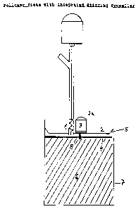
The highly viscous paste 6 is accommodated in a
cylindrical container 7 open at its upper end. The open
end of the cylinder 7 is closed by the round plate 2
arranged in the container 7. The plate 2 is bent out-
wards in the shape of a collar and sealed by a plastic
seal 5. The plate 2 lies on the paste and follows the
paste downwards as it is removed. Disposed in the middle
of the follower plate 2 is a motor 3a and transmission
system 3 on the shaft of which a multiple-blade stirring
propeller 4 is arranged. The shaft terminates in a boss
8 which projects slightly downwards. In the embodiment
illustrated, all the blades are of equal length and
extend over the entire diameter of the cylinder. These
long blades also strip the paste from the cylinder wall,
i.e. residues of paste on the container wall are mini-
mized. The stirring propeller 4 is able to rotate freely
under the follower plate 2. If pseudoplastic pastes of
such high viscosity that the dispenser is unable to
transport them without shearing are used, the propeller
blades shear the upper layer of paste sa that the vis-
cosity of the paste is reduced to such an extent that it
becomes dispensable. A dispenser 1 in the form of an
eccentric screw pump is arranged outside the middle of
the plate 2. The sheared and viscosity-reduced paste is
put to its use, for example in an institutional washing
machine, by this pump, optionally via corresponding
distributing and/or metering elements.
~l l2i'9~
WO 95/09263 8 PCT/EP94/03211
List of reference numerals
1 Dispenser
2 Follower plate
3 Transmission
3a Motor
4 Stirring blades
Seal
6 Paste
7 Paste container
8 Boss
r