Language selection

Search

Patent 2172864 Summary

Third-party information liability

Some of the information on this Web page has been provided by external sources. The Government of Canada is not responsible for the accuracy, reliability or currency of the information supplied by external sources. Users wishing to rely upon this information should consult directly with the source of the information. Content provided by external sources is not subject to official languages, privacy and accessibility requirements.

Claims and Abstract availability

Any discrepancies in the text and image of the Claims and Abstract are due to differing posting times. Text of the Claims and Abstract are posted:

  • At the time the application is open to public inspection;
  • At the time of issue of the patent (grant).
(12) Patent Application: (11) CA 2172864
(54) English Title: COMBINATION STEPLADDER/HANDTRUCK APPARATUS
(54) French Title: ESCABEAU/CHARIOT MANUEL
Status: Dead
Bibliographic Data
Abstracts

English Abstract


A stepladder/handtruck combination is used as a
stepladder in a first position and as a handtruck in a
second configuration. A plurality of steps are positioned
to move between horizontal positions in the stepladder
configuration and positions substantially parallel to the
frame when the combination is being used in the handtruck
configuration. A pair of wheels provides for convenient
transport and a support plate used in the handtruck
configuration is pivotal about a frame member and assumes a
position parallel thereto when the combination is stored.
Links connect the steps to the frame and provide for
displacement of the steps when the combination is moved
between the stepladder and handtruck configurations.


French Abstract

Combinaison d'un escabeau et d'un chariot manuel. L'invention peut être utilisée comme escabeau dans la première position et comme chariot manuel dans la deuxième position. Plusieurs échelons peuvent passer des positions horizontales lorsque l'invention est utilisée comme escabeau à des positions relativement parallèles par rapport au cadre lorsque l'invention est utilisée comme chariot manuel. Deux roues rendent l'invention idéale pour le transport. Une plaque de soutien, qui est utilisée lorsque l'invention est dans la deuxième position, peut être tournée par rapport au cadre et se mettre dans une position parallèle lorsque l'invention est remisée. Des liens unissent les échelons et le cadre et permettent le déplacement de ces échelons lorsque l'invention passe de la première à la deuxième position.

Claims

Note: Claims are shown in the official language in which they were submitted.


- 7 -
I CLAIM:

1. A handtruck/stepladder combination comprising a
first frame, wheels attached to said first frame at a
position adjacent the lowermost position of said first
frame, handles attached to said first frame near the
uppermost location of said first frame, a second frame
pivotally connected to said first frame at a position
adjacent said handles and defining a stepladder in a first
position when said second frame extends outwardly from said
first frame and defining a handtruck when said second frame
extends inwardly and is adjacent too said first frame, a
support plate pivotally connected to said second frame at a
position adjacent the lowermost position of said second
frame, at least two steps pivotally connected to said first
and second frames and extending therebetween when said
second frame is in said first position and being
substantially parallel to said first frame when said second
frame is in said second position.

2. Stepladder/handtruck combination as in claim 1 wherein
said steps are pivotally connected at one end to said first
frame and by links extending between each of said steps and
said second frame.

3. Stepladder/handtruck combination as in claim 2 and
further comprising a third step, said link of said second
step extending between said second step and said third step
and said link of said third step extending between said
second step and said second frame.

- 8 -
4. Stepladder/handtruck combination as in claim 3 and
further comprising reinforcing members extending between
said opposite sides of said second frame.

5. Stepladder/handtruck combination as in claim 4 wherein
said support plate is movable between a first position
wherein it contacts said second frame in its lowermost or
support configuration to restrict further movement of said
support plate and a second position wherein said support
plate is pivotally moved upwardly and assumes a position
parallel to said second frame.

Description

Note: Descriptions are shown in the official language in which they were submitted.


217286~

COMBINATION STEPLADDER/HANDTRUCK APPARATUS
INTRODUCTION

This invention relates to a combination stepl ~ r and
handtruck apparatus and, more particularly, to a combination
steplA~r/handtruck apparatus for home and light duty
industrial uses.

BACKGROUND OF THE INVENTION

Step~ rs are used around the home for many purposes.
They are small and convenient to use. Following such usage,
they are easy to store out of sight. Handtrucks, however,
are used much more infrequently. They are not used around
the home often enough to justify the purchase and they are
generally stored in a remote location where access is not
convenient.

However, handtrucks could be used much more often if
they were convenient and could be used for other purposes to
offset their relatively limited use in the home. A
combination of a handtruck and a portable stepl ~A~r offers
many conveniences including very little addition room for
storage, ease of transport of the steplA~or~ ready
availability for-the handtruck and not a great additional
cost to the consumer.

SUMMARY OF THE INVENTION

According to one aspect of the invention, there is
provided a handtruck/stepl~ r combination comprising a

2:~728B4

-- 2
first frame, wheels attAch~ to said first frame at a
position adjacent the lowermost position of said first
frame, handles attAche~ to said first frame near the
uppermost location of said first frame, a second frame
pivotally connected to said first frame at a position
adjacent said handles and defining a steplA~r in a first
position when said second frame extends outwardly from said
first frame and defining a handtruck when said second frame
extends inwardly and is adjacent too said first frame, a
support plate pivotally ro~n~ted to said second frame at a
position adjacent the lowermost position of said second
frame, at least two steps pivotally connected to said first
and second frames and exten~;ng therebetween when said
second frame is in said first position and being
substantially parallel to said first frame when said second
frame is in said second position.

BRIEF DESCRIPTION OF THE SEVER~L VIEWS OF THE DRAWINGS

A specific embodiment of the invention will now be
described, by way of example only, with the use of drawings
in which:

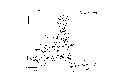
Figure 1 illustrates a steplA~ /handtruck combination
according to the present invention with the frame members
ext~n~ so as to form a stepl A~

Figure 2 is a view from the right of Figure 1 along
II-II but with the apparatus in its closed position;


2:~7~8~4


Figure 3 is a view similar to Figure 2 but taken from
the left along III-III, again with the apparatus in its
closed position; and

Figure 4 is a view s;m; 1 Ar to Figure 1 but illustrating
the steplA~A~r/handtruck combination in its closed position
and operable to be primarily used as a handtruck.

DESCRIPTION OF SPECIFIC EMBODIMENT
Referring now to the drawings, a steplA~A~r/handtruck
co~bination according to the present invention is generally
illustrated at 10 in Figure 1.

It comprises a first frame 11 made from tubular steel
formed into a U-shape as best seen in Figure 3. A pair of
brackets 12 are welded to the frame 11 at a position near
the lowermost point of the frame 11. A rod 13 extends
across the distance between the two brackets 12 and is
perpendicular to the longit~; nAl axis of the first frame
11. Two wheels 14 are mounted on the rod 13 with
appropriate washers and cotter pins (not shown). A pair of
handles 20 in the shape of U-m~mhers are also connected to
the first frame 11 by welding to provide easy h~nAholds for
the operator.

A second frame 21 is pivotally connected to the first
frame 11 at axes 22 at two locations, one on each side of
the first frame 11. Second frame 21 is movable between two
locations, the first or open location being illustrated in

2172~4
-- 4 --
Figure 1 wherein the stepl~AA~r/handtruck combination 10 is
generally used as a steplAAA~r, and a second or closed
position being illustrated in Figure 4 wherein the
steplA~A~r/handtruck combination 10 is generally used as a
handtruck.

A support plate 23 is pivotally connected to the second
frame 21 about axes 24. The support plate 23 abuts the
frame 21 in the downward position as best seen in Figure 2
so that the maximum downward position is that illustrated in
Figures 1 and 3. Support plate 23 is rotatable upwardly and
may assume a position parallel and adjacent to second frame
21 when it is collapsed and when the steplA~A~r/handtruck
combination 10 is being stored or transported.
Three steps 30, 31, 32 are pivotally attAch~A to first
frame 11 about axes 33, 34, 35, respectively. Each step 30,
31, 32 is adapted to extend substantially horizontally when
the steplA~A~r/handtruck combination is used in its
stepl ~AA,~r configuration as illustrated in Figure 1.

Links 40 are pivotally mounted between second frame 21
and first step 30. Links 41, 42 are mounted between s~conA
step 31, third step 32 and c~o~A frame 21 as is illustrated
in Figure 1. The links 40, 41, 42 allow the steps to move
between a first position where the steps 30, 31, 32 are
substantially horizontal in a steplA~A~r configuration and a
s~on~ position where the steps 30, 31, 32 are substantially
parallel with the first frame 11 such as when the
stepl~AA~r/handtruck combination is used in the handtruck

21728~


configuration as illustrated in Figures 3 and 4.

A pair of cross-reinforcing m~mhers 43, 44 are mounted
between the m~mhers of second frame 21 to provide additional
strength and integrity to the steplAAA~r/handtruck apparatus
10 .

OPERATION

In operation, it will initially be assumed that the
steplA~Ae~/handtruck combination 10 is in the storage
position illustrated in Figure 4 except that the support
plate 23 will have originally been in the position
illustrated in phantom in Figure 4. The support plate 23
will be rotated downwardly and the steplAAA~/handtruck
combination 10 will be available for use as a handtruck,
with the wheels 14 contacting the ground and the handles 20
available for ease of hAnAl; ng by an operator. It may be
transported to a desired location, the support plate 23 will
be positioned for supporting a load intenA~A to be conveyed
and, thereafter, the load will be transported all of which
is readily known.

In its alternative configuration as a steplAAA~ the
combination 10 will appear as is illustrated in Figure 1.
In this position, the wheels 14 will be out of contact with
the ground or floor and the first and second frames 11, 21
will assume the position illustrated therein with the steps
30, 31, 32 assl i ng a substantially horizontal configuration
and the second frame being supported on the ground or floor

~17286g
-- 6 --
at its lowermost end 50. The user may conveniently climb up
the steps again as is readily known.

A convenience in the stepl A~ configuration is that
the steplA~ /handtruck combination can be easily
transported by the wheels 14 inten~ primarily for the
handtruck configuration whereas with an ordinary stepl A~
the stepl A~ must be manually carried from the storage
location to the location of use.
Although a specific embodiment of the invention has
been described, such description is by way of example only
and should not be construed as limiting the scope of the
invention as defined in accordance with the accompanying
~1 A;mc,


Representative Drawing
A single figure which represents the drawing illustrating the invention.
Administrative Status

For a clearer understanding of the status of the application/patent presented on this page, the site Disclaimer , as well as the definitions for Patent , Administrative Status , Maintenance Fee  and Payment History  should be consulted.

Administrative Status

Title Date
Forecasted Issue Date Unavailable
(22) Filed 1996-03-28
(41) Open to Public Inspection 1997-09-29
Examination Requested 2003-02-10
Dead Application 2006-03-28

Abandonment History

Abandonment Date Reason Reinstatement Date
2005-03-29 FAILURE TO PAY APPLICATION MAINTENANCE FEE

Payment History

Fee Type Anniversary Year Due Date Amount Paid Paid Date
Application Fee $0.00 1996-03-28
Registration of a document - section 124 $0.00 1996-09-26
Maintenance Fee - Application - New Act 2 1998-03-30 $100.00 1997-12-18
Maintenance Fee - Application - New Act 3 1999-03-29 $100.00 1999-03-09
Maintenance Fee - Application - New Act 4 2000-03-28 $50.00 2000-03-28
Maintenance Fee - Application - New Act 5 2001-03-28 $75.00 2001-02-01
Maintenance Fee - Application - New Act 6 2002-03-28 $150.00 2002-03-13
Maintenance Fee - Application - New Act 7 2003-03-28 $150.00 2003-01-20
Request for Examination $400.00 2003-02-10
Maintenance Fee - Application - New Act 8 2004-03-29 $200.00 2004-02-13
Owners on Record

Note: Records showing the ownership history in alphabetical order.

Current Owners on Record
QUALITY CRAFT IMPORTERS LTD.
Past Owners on Record
BRICE, JOHN NIGEL
Past Owners that do not appear in the "Owners on Record" listing will appear in other documentation within the application.
Documents

To view selected files, please enter reCAPTCHA code :


To view images, click a link in the Document Description column. To download the documents, select one or more checkboxes in the first column and then click the "Download Selected in PDF format (Zip Archive)" or the "Download Selected as Single PDF" button.

List of published and non-published patent-specific documents on the CPD .

If you have any difficulty accessing content, you can call the Client Service Centre at 1-866-997-1936 or send them an e-mail at CIPO Client Service Centre.


Document
Description 
Date
(yyyy-mm-dd) 
Number of pages   Size of Image (KB) 
Claims 1996-03-28 2 50
Representative Drawing 1997-10-29 1 8
Representative Drawing 2000-12-11 1 8
Cover Page 1997-10-29 1 48
Description 1996-03-28 6 186
Drawings 1996-03-28 4 42
Cover Page 1996-03-28 1 16
Abstract 1996-03-28 1 20
Cover Page 2000-12-11 1 48
Fees 2000-03-28 1 35
Correspondence 2000-03-28 1 28
Fees 2003-01-20 1 25
Assignment 1996-03-28 10 418
Prosecution-Amendment 2003-02-10 1 69
Fees 1999-03-09 2 60
Fees 2002-03-13 2 71
Fees 1997-12-18 2 60
Fees 1998-01-26 1 40
Fees 1999-04-21 7 283
Fees 2001-02-01 1 37
Fees 2004-02-13 1 27