Note: Descriptions are shown in the official language in which they were submitted.
f~ ~ ~ ,
HEADGEAR ACCESSORY
FIELD OF THE INVENTION
The present invention relates generally to hats, caps, hooded
garments, and other headgear,. and more specifically to an accessory
therefor which provides for the securing of the long hair of the
wearer of such headgear through a hole in the upper back of the
headgear. The accessory is sewn or otherwise secured over a hole
in the headgear, and includes a plurality of radial slots therein .
which serve to grasp the hair securely to provide security for the
. headgear, as well as providing an attractive closure for the hole
in the headgear.
BACKGROUND OF THE INVENTION
Longer hair which is tied, braided, or otherwise secured in
one or more elongate extensions or "tails" to the back of the head,.
has long been popular among women, and in fact is seen from time to
time among men also. Generally, such hair is gathered toward the
upper back of the scalp, above the location of the rear portion of
the band of a hat or cap, if such is worn.
The result is that the gathering of the hair near the scalp,
which by its nature forms a protruding bundle at that point, must
be stuffed under the hat or cap, with the remainder of the hair
extending outwardly and downwardly below the rear edge or band of
the hat or cap. With closely fitting caps (e.g., billed Or
visored "baseball " style caps, etc.) such a configuration can be
somewhat uncomfortable for the wearer of the headgear. Passing the
hair through the opening above the usual adjustment band of such
1
ww.:.:
h:' ,
caps provides little additional comfort, as it is generally still
too low for optimum positioning relative to the gathered hair at
the upper back of the scalp. In.the case of hats or caps having a
specific) non-adjustable size, there is no such rear opening, which
further exacerbates the situation.
Moreover, many men and women with longer hair also engage in
various vigorous activities (e.g., jogging, etc.). Typically, a
cap or hat is worn in colder conditions during such activities, and
the hair is captured thereunder. This is especially true when a
hooded windbreaker or the like is worn. The result is often that
the longer hair absorbs perspiration due to the activity of the
person, and becomes damp and uncomfortable as a result. Yet,. there
is generally no convenient alternative to allow the longer hair to
remain free during such activities. While one solution would be
simply to cut a hole in the upper back of hats or hoods to be worn,
such a hole would be unsightly and would be uncomfortable for use
when the hair is not tied back~or braided to form a single bundled
extension.
Accordingly) a need will be seen for a headgear accessory
which provides a neat, and attractive passage at the upper back
portion of a hat, cap, hood, or other headgear, for the passage of
the hair of a longer hairstyle therethrough. The accessory must be
easily installable on such headgear, after forming an appropriately
sized hole in the headgear, and should be sufficiently flexible to
provide substantial closure of the opening when it is not needed.
By forming plural slots in the accessory, the flaps of material
defined by the slots will be pushed outwardly and will provide at
least some resilient gripping of the hair passed therethrough, to
provide security both for the hair and for the headgear.
2
.: _._.._._.~._w..._
R
DESCRIPTION OF THE PRIOR ART
U. S. Patent No. 2,864,383 issued to Elizabeth A. Jacks et al.
on December 16, 1958 describes a Holder And Cap Device For A Lady's ,
Pony-Tail Hair-Do comprising a nearly flat, semi-conical outer rim
with a semicylindrical central portion extending outwardly
therefrom. The assembly is open approximately one quarter of its
circumference in the relaxed condition, and is adapted to be
wrapped around a pony tail or other bundled hair fashion by means
of a tie. The device provides no automatic closure or gripping of
10' the hair, as provided by the slotted, resilient material of the
present accessory, and no means of securing the Jacks et al. device
to a hat, cap, or other headgear is disclosed.
U. S. Patent No. 3,041,628 issued to Alvin K. Fish et al. on
July 3) 1962 describes a Novelty Cap formed of.a flat sheet of
material. A gap is provided at the rear thereof, which forms an
opening when the extensions to each side thereof are secured
W together. However, the opening is a fixed part of the cap, rather
than being a part of an accessory therefor; and cannot close or
grip the wearer's hair which passes therethrough, as provided by
20 the slotted and resilient nature of the present accessory.
U. S. Patent No. 4,998,544 issued to Stephen D. Obergfell on
March 12, 1991 describes a Combination Headband And Ponytail
Holder, comprising a tubular component secured to a headband. The
hair is passed through the tubular component and the headband is
secured about the head of the wearer. The device cannot be used in
combination with any other headgear, as provided by the present
accessory, and extends away from the head of the user, unlike the
relatively thin, flat, and planar configuration of the present
accessory.
3
U. S. Patent No. 5,156,171 issued to Joyce E. Goodman on
October 20, 1992 describes a Method Of Adorning A Pony Tail And
Pony Tail Holder. The holder comprises a generally flat, toroid
shaped sheet with an elastic~draw string secured about the inner
opening. The drawstring must be tightened to secure the device
about the hair of the wearer, unlike the present accessory.
U. S. Patent No. 5,170,509 issued to Lynnabeth Leopold on
December 15) 1992 describes a Cap With Decorative Hair Attachment.
The attachment is a ruffled band which is separable,from the cap,
and which may be secured about the hair of the wearer in the manner .
of other conventional hair bands and the like. The device may
include an artificial ponytail or the like, if desired, but.is not
adaptable to a specialized hair passage opening in the cap or
headgear, as provided by the present accessory.
U. S. Patent No. 5,301,696 issued to Rommy H. Revson on April
12, 1999 describes a Decorative Pony Tail Holder And Method Of
Using. The holder comprises a'ruffled band having an elastic
opening therein, through which the hair of the wearer may be
passed. The opening cannot provide full closure when it is not
needed, nor is the device adaptable to application to an opening in
an existing cap or other headgear, as provided by the present
invention. '
U. S. Patent No. 5,321,854,issued to Robert A. Rronenberger on
June 21, 1994 describes a Headwear Piece With Opening To
Accommodate Wearer's Hair. The headwear piece is a relatively
tight fitting, visored or billed cap ("baseball" type cap), through
which a supplemental hole .has been formed in the upper rear
thereof. Rronenberger has recognized part of the problem with the
location of the hole in the cap as a response thereto, but requires
4
2173063 ,
a specialized cap with no closure means for the opening therein,
rather than adapting a more attractive and general solution
applicable to virtually any headgear, as with the present
invention. Moreover, the present accessory provides automatic
closure of the opening due to the slotted configuration, as well as
some gripping of the hair passing therethrough due to the resilient
nature of the material, neither of which advantages are provided by
Rronenberger.
U. S. Patent No. 5,359,733 issued to Garry A. Brannon et al.
on November 1, 1994 describes Patch Attachment For Hats, comprising
mating hook and loop fastening elements respectively permanently
secured to a baseball type billed cap and to display patches
removably securable thereto. No holes through either the cap or
the display patches are disclosed to provide for passage of the,
hair of a wearer of the cap, therethrough.
U. S. Patent No. D-173,620 issued to Rose Rrieger et al. on
December 7, 1954 describes a design for a Hat including an
apparently elastically gathered opening in the crown thereof. The
opening cannot be closed and is not adaptable to different
headgear, as with the present accessory.
U. S. Patent No. D-343,274 issued to Concetta M. Paterek on
January 18) 1994 describes a design for a Jug Handle Hat. The same
points made immediately above concerning the lack of complete
closure and adaptability, are also noted here.
Finally, Canadian Patent No. 506,725 issued to Victor T.
Hoeflich on October 26, 1954 describes a Paper Hat formed of a flat
sheet having a crenelated edge. The sheet is rolled to form a
cylinder, and the crenelated edge is drawn closed to form the crown
of the hat. A closed patch is placed over the crown. The crown
5
C P
closure provides no opening for hair or other purposes, as
provided by the present accessory, is not adaptable to use with
other types of headgear due to its integral formation from a
specifically configured flat sheet, and moreover cannot be
moved to a location other than the center of the crown in any
case.
None of the above noted patents, taken either singly or
in combination, are seen to disclose the specific arrangement
of concepts disclosed by the present invention.
SUH~IARY OF THE INVENTION
By the present invention, an improved headgear accessory
is disclosed.
In accordance with an embodiment of the present invention
there is provided a headgear accessory adapted for installation
to a headgear article having a hole in the upper rear portion
thereof for the passage therethrough of the hair of a wearer
of the headgear, the headgear accessory comprising: a generally
flat, planar, flexible, and resilient sheet of material having
a periphery, a center, and a plurality of slots radiating from
the center outwardly across the sheet toward the periphery: the
slots defining a plurality of radially disposed segments in the
sheet, with the segments being resiliently distensible to
resiliently grip and conform to the hair of a wearer of the
headgear accessory as the hair is passed therethrough; and each
of the segments has edges adjacent to corresponding the slots,
and the edges of the segments include stitching therealong
providing additional strength and finish: whereby the headgear
accessory may be passed over the hair of a wearer thereof by
means of resiliently distending the segments to open the slots,
and the segments may flexibly and resiliently close about the
hair passing therebetween to secure the headgear accessory to
the hair of a wearer of the headgear accessory.
6
xt;..
In accordance with another embodiment of the present
invention there is provided an article of headgear comprising:
a headgear article having an upper rear portion, with the upper
rear portion including a hole therethrough adapted for the
passage therethrough of the hair of a wearer of the headgear
article: a headgear accessory secured concentrically across the
hole through the headgear article, with the headgear accessory
comprising a generally flat, planar, flexible, and resilient
sheet of material having a periphery, a center, and a plurality
of slots radiating from the center outwardly across the sheet
toward the periphery: the slots defining a plurality of
radially disposed segments in the sheet, with the segments
being resiliently distensible to resiliently grip and conform
to the hair of a wearer of the headgear accessory as the hair
is passed therethrough: and each of the segments of the
headgear accessory has edges adjacent to corresponding the
slots, and the edges of the segments include stitching
therealong providing additional strength and finish: whereby
the headgear article and the headgear accessory secured thereto
may be passed over the hair of a wearer thereof by means of
resiliently distending the segments of the headgear accessory
to open the slots and passing the hair through the hole in the
headgear article and the slots of the headgear accessory, with
the segments of the headgear accessory flexibly and resiliently
closing about the hair passing therebetween to secure the
headgear article to the hair of a wearer of the headgear
article.
With these and other features in view which will more
readily appear as the nature of the invention is better
understood, the invention consists in the novel combination and
arrangement of parts hereinafter more fully described,
illustrated and claimed with reference being made to the
attached drawings.
7
,i
BRIEF DESCRIPTION OF THE DRAWINGS
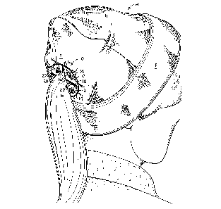
Figure 1 is a perspective view of a hat or cap showing the
present headgear accessory installed thereon, and the features
and function thereof:
Figure 2 is a top and rear perspective view of the present
headgear accessory having an alternative peripheral shape, and
installed on a closely fitting visored, baseball style cap;
Figure 3 is a right side and rear perspective view of
another embodiment of the present headgear accessory having
another peripheral configuration, and installed in the back of
a hooded garment:
Figure 4 is a plan view of the headgear accessory of
Figure 2, more clearly showing its features in greater detail:
Figure 5 is a plan view of an alternative configuration
of the present headgear accessory:
Figure 6 is a plan view of another alternative
configuration showing three equally spaced slots therein: and
Figure 7 is a plan view of yet another configuration,
showing a different peripheral shape.
Similar reference characters denote corresponding features
consistently throughout the several figures of the attached
drawings.
DETAILED DESCRIPTION OF THE PREFERRED EMBODIMENTS
Referring now particularly to Figure 1 of the drawings,
the present invention will be seen to relate to a headgear
accessory 10, which is attachable to an article of headgear
such as the hat or cap H of Figure 1. The upper, rear portion
R of such headgear includes a hole or passage O therethrough
(shown in broken lines in Figure 1), adapted to allow the
passage of the longer hair L therethrough, so the hat H (a knit
stocking or other style cap or hat, which may have a brim B or
alternatively, brimless construction, etc.) may be worn
comfortably back on the head.
8
V.r. :~ :... I
t
The present headgear accessory 10 is secured across
(either outside or inside) the hole O in the headgear, to
provide for the hair length L (ponytail, braid, etc.) passing
there through. The accessory 10 may be secured to the hat or
cap by means of stitching, iron-on or other adhesives, etc.,
as desired. The accessory 10 includes a plurality of slots 12
extending thereacross, from a center point radially outward to
end near the periphery 20 of the device. (The plan views of
various embodiments of the present accessory, as shown in
Figures 4 through 7, provide a clearer disclosure of the
arrangement of the slots.) The slots divide the accessory into
a plurality of flaps or segments 14, which segments 14 spread
and distend as the length of hair L is passed through the hole
O in the hat or cap H, and further through the slots 12 of the
headgear accessory 10 secured thereto.
The present headgear accessory 10 is formed of a flat,
planar, flexible, and preferably resilient sheet of material,
in order to provide the required flexibility of the flaps or
segments 14 to conform to the hair length L which is passed
therebetween when the headgear H is placed upon the wearer's
head. A neoprene sheet material has been found to work very
well for the purpose, although other materials may be
substituted therefor if desired. The neoprene provides the
required flexibility, and further is resilient to urge the
closure of the segments 14 about the hair length L passing
therebetween, to provide some grasping of the hair length L for
greater security of the headgear H on the wearer's head. Yet,
the flexible nature of the material allows the accessory 10,
and any headgear H to which it is secured, to be donned and
removed readily without undue difficulty.
9
~~ ~,
. For greater durability, as well as to provide a more
attractive a
ppearance, the neoprene sheet may be overlaid with a .
fabric (preferably synthetic) material 16 (e.g., nylon) as~ .
indicated by the woven pattern on the surface of~the accessories
disclosed in the various drawing figures. This fabric overlay 16
increases the strength of the.composite sheet assembly, and may be
provided in matching or contrasting colors to the headgear to. which
the accessory is secured, as desired. Further structural strength
for the accessory 10 may be provided by stitching 18 around the
periphery 20 thereof, and additional stitching 22 along the edges
of the flaps or segments 14, as desired. A "buttonhole" type
stitch has been found to work well for securing the edges of~ the
flaps or segments 14, and a similar stitch, or alternatively a more
.decorative embroidery or other design, may be used for the
peripheral stitching 18. As in the case of the fabric overlay, the
,' stitching 18 and/or 22 may be provided in either matching or
contrasting colors to the headgear and/or the fabric overlay
material of the accessory 10, as desired.
Figure 2 discloses an upper rear perspective view of a closely
fitting cap C having a bill or visor V, and having an embodiment
l0a of the present headgear accessory installed therein. As in the
case of the hat H of Figure 1, the baseball style cap C of
Figure 2 also includes a hole or opening 02 in the upper rear
portion R2 thereof. (It will be seen that the various
embodiments of the present accessory are adaptable to virtually
.any type of hat or cap, including caps C as in Figure 2 which
have rearwardly disposed adjustment bands, not shown, or are
of a specific size.)
While the headgear accessory 10 of Figure 1 incorporates
a circular periphery 20, the periphery 20a of Figure 2 will be
seen to be formed of a plurality of relatively short and
regular convex curves, in a "rosette" pattern R2. A plan view
of this embodiment is shown in its entirety and in detail in
Figure 4 of the drawings. The function and structure of the
accessory 10a of Figures 2 and 5 are identical to those of the
accessory 10 of Figure 1, with accessory 10a having a plurality
of radially disposed slots 12a extending from the center 24
thereof (shown in Figure 4), which slots 12a define an equal
number of segments 14a. The base material may include a fabric
overlay 16a, and peripheral and segment edge stitching or
embroidery 18a and 22a. The hair length L passes through the
hole or opening 02 in the cap C, and further through the opened
slots 12a between the deflected and distended flaps or segments
14a, as described in the embodiment of Figure 1. It will be
understood that any of the embodiments of the headgear
accessories of the present invention are adaptable to virtually
any type of headgear, and are not limited to specific headgear
and accessory combinations as shown in the drawing figures.
Figure 3 discloses yet another adaptation of the present
invention, wherein a headgear accessory lOc is provided in the
upper rear portion R3 of the hood D of a hooded garment (e. g.,
windbreaker, jacket, etc.). The accessory 10c is again secured
over (or alternatively, immediately within) a hole or opening
03 formed in the upper rear portion R3 of the hood D of the
garment, as in the openings O and 02 shown in the hats and caps
H and C of Figures 1 and 2, respectively: the principle is the
same in each case.
The specific configuration of the headgear accessory lOc
of Figure 3 is more clearly shown in its entirety in the plan
view of Figure 5, so the reference characters denoting the
details of the embodiment of Figures 3 and 5 are noted only in
Figure 5, in order to provide clarity in Figure 3 of the
11
's~ ~h :n~'~' .;~ g
drawings. The accessory lOc of Figures 3 and 5 will be seen
to have a square or rectangular periphery 20c, with the sheet
of material divided by four slots 12c radiating from a central
point 24a. While the slots 12c are shown diagonally disposed,
it will be understood that an orthogonal slot arrangement is
also possible. The diagonal arrangement provides longer slots
than an orthogonal arrangement, if such longer slots are
desired. The slots 12c separate a corresponding number of
flaps or segments 14c. A fabric overlay 16c may be provided
over the underlying base material sheet, with peripheral and
segment edge stitching or embroidery 18c and 22c, respectively,
being provided, as desired. It will be noted that the headgear
accessory embodiment lOc of Figures 3 and 5 is identical in
both Figures, but that it is shown installed diagonally on the
upper rear portion R3 of the hood D in Figure 3. The
configuration is the same in both Figures, however, as noted.
Figures 6 and 7 disclose still further configurations of
the present headgear accessory, respectively described as
accessories lOd and 10e. These accessories lOd and l0e are
basically similarly configured to the headgear accessories 10a
through 10c discussed above, in that they are formed of a flat,
flexible sheet of material having a plurality of slots 12d/12e
extending radially from a center point 24b/24c. The slots
24b/24c serve to divide the area of the respective headgear
accessories lOd/l0e into a plurality of equal flaps or segments
14d/14e, which segments each include a fabric overlay 16d/16e.
Stitching or embroidery 18d/18e may be provided about the
respective peripheries 20d/20e of the respective accessories
10d/10e, and further stitching 22d/22e along the edges of the
flaps or segments 14d/14e, similarly to the earlier discussed
embodiments. However, the embodiment 10d of Figure 6 will be
seen to have a hexagonal configuration, with only three slots
12d dividing a corresponding three segments 14d. Other numbers
of slots and segments may be provided as desired. The
12
i
embodiment 10e of Figure 7 will be seen to be similar to the
embodiments 10 through 10c, in that four slots 12e divide the
sheet into four equally sized segments 14e in a cruciform
configuration. Only the shape of the periphery is different,
with the periphery 20e of the embodiment l0e of Figure 7 having
an octagonal shape. Again, other peripheral shapes may be used
as desired, with differing numbers of slots and corresponding
numbers of segments or flaps provided, as desired.
In summary, the present headgear accessory in its various
embodiments, will be seen to provide a neat, orderly, and
attractive means of allowing the hairdo of a person having
relatively long hair, to flow from a hat, cap, or other
headgear without being trapped beneath the headgear or within
an outer garment. By providing the selected hat, cap, hood,
etc. with a suitable hole or opening in the upper rear portion
thereof, the present headgear accessory may be secured (sewn,
glued, etc.) thereover, to conceal the relatively unsightly
hole in the headgear. While only one hole and a corresponding
one headgear accessory has been shown in each example, it will
be seen that more than one accessory may be installed in any
given headgear article, e.g., for plural braids, etc., if
desired.
13
'~'. ,~ . .~,
The resilient nature of the preferred neoprene' material
.results in the flaps or segments of the accessory folding to a
flat, planar and substantiall closed
Y position when not biased open
by gathered hair passing therethrough. As the flaps or segments
are pushed to .a relative outwardly disposition, if the hair is
pulled back through the accessory (and headgear to which it~is
secured), the edges of the flaps or segments will tend to be drawn
back toward their normally relaxed and closed disposition, thereby
providing some additional gripping of the hair to provide greater
security to retain the headgear on the head of the wearer thereof.
The peripheral and segment edge stitching provides not only .
additional structural strength for the present headgear accessory,
but also provides decoration in matching or contrasting colors to
the fabric overlay material and/or to the headgear to which the
accessory is secured. Thus, the present accessory will be seen to
provide an attractive solution for.a problem which has existed for
.some time, i.e., the arrangement of longer hair beneath or
outside of a hat or other headgear, and in addition the
retention of the headgear on the head of the wearer.
. It is to be understood that the present invention is not
limited to the sole embodiments described above, but encompasses
any and all embodiments within the scope of the following claims.
' 14
et'