Note: Descriptions are shown in the official language in which they were submitted.
2 1 7308 1
_
PaCent Appli~ation
DockeC #Z~771. 00150
~PP~ T~,'; . FOE~ NG ~F~ v~: A~T~ ~12F~
~nrn~ 0~ NV ~r- 1 1 0
el ~ o~ ~ t~v~t~ nn
The pre~ent invention per~ain-q to ga~-liquid
conta~ting towe~ and, more particularly, to an i~proved
downcome~-tray a~e~bly incorpora~ing an acti~e bridge
~etween adj~cent downcomers, an a~tive support ring
wi~hin the tower, and active wa~her~ ~ecured ehereto for
increasing the effecti~e acti~e ~rea of the tray.
~tory of t~h~ Prtor l~t
Dl~tillation column~ are u~ilized to separate
selected ~p~nent~ ~rom a m~lticomponent strea~.
Generally, such ga~-liquid contact columns ~tilize either
~ray~, packing or co~ination~ of each. In recent years
~he ~rend ha~ been to replace the ~o-called ~bubble cap~"
Iew~:q 973g .1
2 1 7308 1
-
Patent Application
Doc~et #27~71.00150
by sieve and ~alve ~ray~ in mo~t tray column design~.
Addi~ionally, rando~ ~du~ped) or ~tructured packing~ have
bee~ utl~ized in combination with ~he tray~ in o~der to
effect improved 6eparation of the c~ nt~ in the
~tream.
Succes~ful fractionation in the column i3 ~ n~Pnt
upon intimate contact between liquid and vapor phase~.
So~e vapor and liquid ~tar~ de~ice~, such as tr~y~, are
characterized by rel~tively high pre~ure drop and
relatively high li~uid hold-up. Another type of ~apor
and liquid contact apparat~, namely structured high
efficiency packing, ha~ al~o become popular for certain
applicatio~. Such packing i-~ energy efficient becau~e
i~ ha~ low preseure drop and low liquid hold-up.
: However, the~e very propertie~ at time~ make colu~n~
e~li~pe~ with ~tructured pa~king dif~icult to opera~e in
a ~table, con~istent m~nn~r Moreover, many appll~ations
Rimply ~eq~ire the u~e of trays.
~ractionation ~olumn trays generally come in one of
two configu~ation~: cros-flow and counter flow. The
tray~ generally consist of a ~olid ~ray or deck h~ing a
pluFality of aperture~ and are in5talled on ~upport ring~
within rhe to~er. In cro~fi-~low tray~, vapor ascend5
through the aper~ure~ and co~tacts ~he liquid moving
across the tray; through ~he ~aetive~ area thereof In
the ~cti~e area, l~quid and vapo~ mix and fra~tlonation
occur~. The liquid i~ directed onto the ~ray by mean~ of
a vertical ~h~nn~l f~om the tray a~ove. Thi~ ~.h~n~l iB
~: 49739. 1
21 73081
-
Patent Application
Docket #27771 00150
referred to as the Inlet Do~ncomer. The liquid ~ove~
acros~ the tray and exits thr~u~h a similar ~h~nn~l
referred ~o as ~he Exit ~owncomer. The 1ocaeion of the
downcomer~ determine the ~low p~ttern of the liquid. If
there are two Inlet Downcomers and the liquid i~ ~plit
into two ~treams o~er each tray, it i~ called a two pas~
tray. If there is only one Inlet and one O~tlet Downcomer
on opposite ~ide~ of the tr~y, it i5 called a ~ingle pa~s
tray. For two or more pa~se~, the tray i8 of~en referred
~o a~ a Multipas~ Tray. The nu~be~ of pa~6es generally
increa~es a~ the required (de~ign) liquid rate increa~e~.
It i~ the active area of the tray, however, which i6 of
critical concern.
Not all areas of a tray are active for ~apor-liquid
contact For example, the area~ a~ng the perimeter of
the tray and ~nder the Inlet Downcomer are generally
~olid region~. To atte~pt to gain more area of the tray
for v~por~liquid contact, downcomer~ are of~en ~loped
The maxirn~m vapor/liquid handli~g capacity of the tray
generally increases with an increa3e in the active or
Bubbling Area. There i~, however, a limit a~ to ho~ ~ar
one can ~lope the downcomer (~ in order 'co increa~ae the
~ubbling Area otherwise the ch~nn~l will beco~e too
small. Thi~ ~an restric~ the flow of the liquid and~or
re~trict the diEengagement of vapor retained in the
liquid, cau~e liquia to back up in the downcomer, and
thus pre~aturely limit the normal ~Yi~ vapor/liquid
handling ~apacity of the t~y
IPtll~L: 49739. 1
2 1 7308t
Patent Application
Docket ~27771.00150
A ~ariation ~or increasin~ the Bubbling Area and
hence vapor/liquid handling çapacity i~ a ~ul~iple
downcome~ tray. There are usually ~any box shaped
vertical rh~nnels in~talled in a ~ymmetri~al pattern
acros~ the tray to direct liquid on~o and off of the
tray The downcomer~ do not extend all the way to the
~ray ~elo~ but ~top ~hort of the tray by a predetermined
diG~ance which i3 li~ited by a sufficient ~pace to per~it
disengagement o~ any vapor retained in the liquid
entering the Exit ~owncomer. The down~omer pattern ~ay
be rotated go or 180 degree~ be~ween ~ccee~ive tray~
The bottom o~ the boxe~ i~ solid except for slot~ ~hat
di~ect the liquid onto the tray belo~. Such tray~ fall
into the c~tegory of Multipas~ Trays whi~h are usually
u8ed for high liquid rateEi. A critic;~l fea~cure in ~uch
tray~ is ~he a~ailable active area of the tray. De3ign~
~or increasing thi~ active area a~e thu~ of major import
in tray fabrication.
~ariou~ techniques have ~een de~eloped for
~0 increasing t~e tray active area in proces~ colu~n
design~. For example, U.S, Patent No 4,956,127,
a~signed to the a~ignee of the present invention,
illu~trates a tray de~ign with a rai~ed active area
di~posed beneath the downcomer inlet for increa~ing the
2~ active area of the tray. U S Patent No. 5,164,12~, also
a3~igned to the a~ignee of the pre~ent inve~ion, again
addresse~ a do~ço~ ray a~embly fo~ ~apor liquid
contac~ ~owers featuring imp~ov~d downcomer and tray
IPDAL: 49739. 1
2l7308l
Patent ~pplication
Docket #277~1.00150
de~igns for ~h~ncing the ac~i~e area of the ~ray a~ well
a~ the balance of liquid flo~ th~reon. ~he balance of
llquid flow i~ of primary ~i~nifisance in ~uch tray~
set forth in U.S. Patent ~o. 5,192,~66, al~o aesigned to
the aQ~ignee of the pre~ent invention, method~ of and
apparatu~ for ~low promotion and effecti~e ~alance of
flow upon a cray i8 an impor~ant de~ign feature. When
flow i~ uneven o~ stagnated, the efficiency of the
chemical process column i~ drastically reduced Fo~ this
rea~on, these and other innovations in the downcomer-tray
area have received con~idera~le attention.
In addieion to the abo~e, the technology of gaC_
liq~id contact addresse~ many other performance i~ues.
Exa~ple~ are ~een in ~everal prior ar~ patent~, which
include U.S. Patent No. 3,959,419, 4,604,247 and
4,597,916, each assigned to the a~ignee of the present
invention and U.S. Patent No. 4,603,022 issued to
Mits~blshi Jukogyo Kab~h;~; ~ai~ha o Tokyo, Japan. A
particularly rele~ant re~ence i8 seen in U.S. Patent
~o. 4,499,035 a~signed to Union Carbide corporation that
tPA~he~ a ga~-liquid contacti~g tray with improved inlet
bubbling me~ns. A cros~-flo~ tray of the type de~cribed
above i9 t~erein ~hown with i~ ed means for initiating
bubble ~cti~ity at the tray inlet ~...pLi~ing spaced
apart, imperforate ~all memberu extending subs~aneia~ly
ve~tlcally upwardly and ~ransver~e to ~he liqu~d flow
path. The ~tructural configuration i~ ~aid eo promo~e
activity o~er a larger tray s~rface than that afforded by
97 :~ 9
21 73081
Patent Application
Docket #27771.00150
~i~ple perforated tray asse~blies. ~hi~ i8 accomplished
in part by p~oviding a rai~ed re~ion adjacent the
downcomer area for facilitating vapor ascen~ion
therethrough.
U.S. Paten~ No. 4,~50,000 ae~igned to Shell Oil
r~ny tea~h~ apparatus for contacting a liquid with a
ga~ in a relationship between vertically ~tacked ~rays in
a tower. The aperture~ in a given tray are provided fo~
the passage of ga~ in a ~nner le~s hampered by liq~id
coming fro~ a discharge mean~ of the nex~ upper tray.
Thi~ is provided ~y perforated hou~ings mounted to the
top of the tray deck beneath the downco~ers fox breaking
up the de~cending li~uid flow Such advances i~prove
tray efficiency within the confine~ of prior art
s~ructure~. ~ikewi~e, U ~. Patent No. 4,543,219 a~igned
to Nippon Kayaku Kabushiki Kaisha of To~yo, ~apan teache~
a ~affle tray to~er. The operational parameters of high
gas-liquid contact efficiency and the need fo~ low
pre~sure loss ~re ~et orth. such reference~ are u~efu~
in illu~trating the need for high efficiency vapor liquid
contact in t~ay p~oce~ tower~. U.S Patent
~o. 4,504,426 issued to Carl T. Chuang et. al and
as~igned to ~tomic Ener~y of C~n~ Limited i~ yet
another example o ga~-liquid contacting apparatus. ~hi~
reference li~ewi6e teaehes the multit~de of advantageQ in
i~proving efficiency in fr~ctionation and modifications
in downco~er-tray de~igns The perforated are~ of the
rpD~ 9739.1
2 1 7308 ~
Patent Appli~atio~
Docket #27771.00150
tray i~ ex~ended beneath the do~ncomer with between 0 to
25~ les~ perforation are~.
Yet ano~her reference is 5een in U.S. Pa~ent
No. 3,410,540 i~sued to W. Brucke~t in 196a. A do~ncomer
o~tlet baffle i8 there~n ~hown ~o control the discharge
of liquid therefrom. The baffle may include either a
static seal or dynamic ~eal. In t~i~ rega~d the or~nin~s
from the downcomer are su~ficiently ~mall to control
di~charge and may be larger than the tray per~oration6
o and of cir~ular or rectangular ~hape. The ~ran~ient
force~ which ~ay di~rupt the operatio~ of a downcomer are
al~o more fully elaborated ~herein. The~e ~orce~ and
related vapor-liquid flow pro~lem~ mu~t be con~idered for
each application in which a dow~o~r feeds an underlyin~
__ tray.
Yet a further reference addres~ing downcomer tray
assemblie~ and methods of ~ixing vapor with liquid from
a di~charge area of a ~ e . - r i~ Bet ~orth a~d chown in
U.S. Patent No. 4,956,127 (the '127 Patent) a~igned to
the a~signee of the p~e6ent invention. ~n the '127
Patent, a rai~ed acti~e inlet area a~ ~et ~orth and
shown, which inlet area is provided for the venting of
~apo~ from ~he tray therebeneath. The raised inlet area
reduces fluid press~re of the ~apor to facilitate the
flo~ of a~r~n~ing vapor therethrou~h. A ~erie~ of
louvers disposed on the rai~ed active inlet area
~electively direct~ the upward flo~ of vapor in~o ~e
liquid region below the ~owncomer to generate more
Ie~L: ~.9739 .1
2 1 7308 1
-
Patent Application
Docket #~7771. 00150
ef f icient vapor llquid contact and r~duced back mixing
acrose the tray. The di6cl~a~ge of liquid ~rom the
downcomer onto the raised active inlet area, tho~gh
ef ~ecti~ue, ha~ been ~hown to re~ult in weeping a~ ~che
S di~charged liqu~d from the downcome~ pa~se~ through the
~per~ure~ of the active inlet area. Additionally, th~
liquid ~p~ hing outwardly from the down~omer increase~
the frothinen~ thereof and ~AIlR~ llquid drop~ to be ~ore
easily su~pended.
As set foreh above, the effectivenes~ of downcomer-
tray operation i~ directly related to ~luld flow
conf igu~ation~ . When dowr~cr~mF~r weirs and other
stxuctural ~pect~ of the tray inhibit either vapor or
liqllid flo~, to~rer efficiency is reduced. In multiple
; downco~er tray assemblie~ ~ the tray decks are literally
divided by the downcomer Th~s tray divi~ion can re~ul~
in unequal flow on oppo~ite ~ide~ of the downco~er.
Likewi~e, ~tructural member~, such a6 support beam~
di~poQed under tray areas, can interfere with asoPn~in~
v~por flow. Other structural member~ ~uch a~ tray hold
down and securen~ent de~i~es o~ten dispo~ed on tray
perimeter~ may likewi~e present solid, non-active tray
area~ which preven~ vapor flo~. such inactive, ~olid
area6 reduce tray e~ficiency as descxibed above. It
zs would ~e an ad~antage therefore to provide a tray
aQsembly addre~ing the problem~ of both ~iguid and ~apor
flow uniformity in a configuratlon which maximize~ the
~Pl~ 49739. 1
2 1 7308 1
._
Patent Application
Do~ket #27771.00150
active area o~ the tray and simpli~iee certain ~tructural
aspect~ ~herein to maximize ~he efficiency.
Such a downcomer-tray a~sembly is provided ~y the
pre~ent in~ention ~erein a perforated column ~upport
rlng and perforated wa8hero are ~ecu~ed along the tray
peri~eter to increase the active area of the tray.
Addi~io~ally, a structural baffle ~y~tem m~y be ~ed to
~upport the downcomers, po~itioning them a~o~e a ~ray
area incorporating venting ch~mhrr~ upst~ on the
lo tra~ deck therebelow and active ~bridges~ therebetween.
The abeence of 5tructural ~upport beams beneath the tray
deck in conjunction with the active ~ridges and tray
perime~er impro~e the efficiency of the ~olumn. The
ba~le support may be further conetructed in multiple
downcomer configuration~ to permit liquid flow
thereacros~ for flow equalization ~pon the t~ay.
.~y of th~ T~vPnt;on
The pre~e~t invention pertains to downcomer tray
~sem~lies for che~ical process colu~n~ More
particularly, one ~spe~t of the invention includes a
downcomer-tray a~Yem~ly for a proces~ column of the type
wherein liguid flo~s do~nwardly from a fir~t tray throu~h
a fir~t downcomer onto a se~ond ~ray and acro~s the
acti~e area~ thereo~. Across the~e acti~e tray areas
vapo~ flowa up~ardly fo~ ineeraction and ma~s transfer
with the liquid The liquid then pa~e~ from the second
tray ~hrough another dow~com?r. The pre~ent invention
~PWU,:n97~9 1
- 21~3~1
Patent Application
Docket ~27771.00150
co~pri~e~ an actîve ~ o~- ring underlying the perimeter
of the trays and an acti~e washer in secureme~t thereto.
In another a~pect o~ the invention, ba~fle~ are connected
to the downcomer~ for the support thexeof by a p}urality
of angulated support member~ ~ecured one end to the
baffle and ~t a ~econd end to the tray-downcomer ~egion.
I~ another aspect, the invention ~elate~ to a
~ultiple downc~r?r tray aQse~bly for a chemical pxoces8
column of the type wherein liquid flow~ down~ardly and
~apor flows upwa~dly ln in~eraction therewith and wherein
liquid flow~ upon a fir~t tray and downwardly from the
fir~t tray ~hrough a first series of downco~er~ disposed
therein onto a second tray and thereupon adjacent a
~econd 6erie~ of downcomer~ disposed thexein. The
- invention compri~es an active ~upport ring around the
perimeter of the trays for the outward ~upport thereof
and a plurality o~ support baf~les extending along at
lea~t some of the do~n~om~rG for the intermediate suppo~t
thereof. A plurality of mounting membe~ secure the
downcomer~ to the support baffle~ and at least two
downcomer~ are dispo~ed in ~paced, end to end
relation~hip within one of the ~rays facilitating an
active tray bridge 8e~tion diupo~ed between the end~
thereof Thi~ construction permit~ a~cending vapor flow
thxouyh the bridgc, which in conjunction with the active
6upport ring incre~ee the tray active area.
~r~Pf D~r;~tio~ of ~h~ nr~ngq
97:~9 . 1
- 2 1 7308 1
-
Paten~- Application
Docket #27771.00150
Por a more complete ~nder~n~ing of the pre~ent
invention and for further objects and ad~antage~ thereof,
reference may now be had to the follo~in~ description
taken in co~junction with the ao~o~r~ying dra~ing6 in
5whi~h:
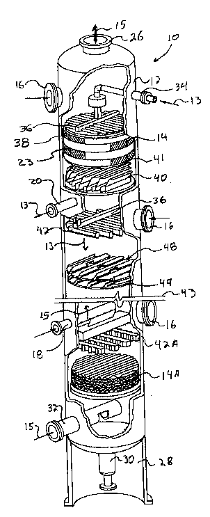
FIG. 1 is a per~pe~ive view of a packed column with
various sections ~ut away for illu~t~ating a variecy of
tower internals and one embo~ nt of a ~ownco~er tray
a~embly constructed in accordance with the princip~e~ of
10the present in~ention di~po~ed therein;
FIG. 2 i~ a per~pective view of a down~o~er-tray
as~embly con~tructed in acoo~dance with ehe principles of
the pre6ent invention;
FIG. 3 is a diagram~atic, cros~-~ectional view of
the improved downcomer ~ay ~ssembly o~ FIG. 2, taken
along lines 3-3 thereof;
FIG 4 is an enlarged, 6ide eleva~ional view of the
down~omer of FIG 3 taken along line~ 4-g thereof
F~G. 5 i~ an enlarged top plan view of the
20downcomer-tray a~embly of FIG. z;
FIG. 6 i~- an enlarged, fragmentary, per~pective view
of ~he acti~e tray 9u~0t L ring of ~IG. 2;
FIG~ 7 is an enlarged, ~ide elevational, cr~ss
~eccional view of the support ring mounting of FIG. 6,
25taken along line~ 7-7 thereof;
FIG. 8 i~ an enlarged, top plan view of the active
wa~her o~ FIG. 7; and
IPD~: ~9739.1
2 1 730~ ~
P~tent bpplication
Docket #27771.00150
PIG. 9 i~ a top plan view of an alternative
emh~iment of a portion of t~e tray of FIG. 2.
~tA 1 1 P~ ne~r~ on Of ~h~ Pref~re~ F.mh~A;~C~
Referring fir~t to F~G. 1, there i8 shown a
fragmentary, per6pective ~iew of an illu~trative packed
ex~hange tower or ~olumn with ~ariou~ section~ cut a~ay
for ~howlng a ~ariety o~ tower in~ernal~ and the
utilization o~ one e~o~; ~ t of the tray a6s~mb1y of the
pre6ent in~ention. The exchange column lo of FIB. 1
compri6es a cylindrical tower 12 ha~ing a plurality o~
packing ~ed layer~ 14 and ~ray~ di~po~ed therein. A
plurality of man~ays 16 are likewi~e con8~r~cted for
facilit~tin~ access to the internal region of the tower
12. Al~o provided are ~ide ~tream draw of~ line 20,
liquid ~ide feed line 18, and ~ide ~tream vapor feed line
or reboiler return ~ine 32. A ~eflux return line 34 i9
pro~ided ~top t~e tower 10.
In operation, liq~id 13 i8 fed into the to~er 10
through reflux return line 34 and ~ide ~tream feed input
feed line 18. ~he liquid 13 flow~ downw~rdly throu~h the
tower and ul~imately lea~e~ the to~er either at ~lde
~ream draw off 20, or at bottom stream dra~ o~f line 30.
In it~ downward flow, ~he liquid 13 is depleted of ~ome
material which e~aporate~ from it as it pa~e~ thro~gh
the trays and packing bedG, and i~ enriched or added to
by ~aterial which co~nqeG into it out of the vap~r
stream. S~ill referring to FIG. 1, the ~Yrh~n~e column
IPD~ 49739. 1
2 1 7308 1
Patent ~pplication
Docket #27771.00150
10 is diagrammatically c~t in h~lf for purpose~ of
clariey. In this illustration, the colu~n 10 includes a
~apor outlet in overhead line 26 di~posed atop the to~er
12 and a lower ~kirt 2~ disposed in the lower re~on of
the to~er around bo'ctom E~tream ~akeoff lir~e 30 coupled to
a reboiler ~not ~hown). Reboiler return conduit 32 i~
~hown di~posed above ~he ~3ki~t 2~ for recycling vapor
thcrein upwardly through the trayR and~or packing layers
14. Reflux fro~ conden~er~ i~ pro~ided in the upper
tower region 23 through entry condu~t 34 wherein reflux
i~ di~tributed througho~c a liquid di~tributo~ 36 acros~
upper packing bed 3 a It may be ~een that the upper
pa~king bed 38 is of the structur~d packing variety. The
regione of the ~xch~n~e colu~n 10 beneath the upper
packing bed 38 are ~hown for the purpose of illustration
and include a liquid collec~or 40 di~po~ed beneath a
support grid 41 in 8U~O~ L of the upper struc~ured
packing 38. A liquia di~tributor 42, adapted for
redistributing liquid 13, is likewi~e di~po~ed there-
beneath. A ~econd type of di~eributor 42a is ~hown below
the cut-line 43 and di~po~ed a~o~e ~tructured packing
14A. The column 10 i~ preeented with cut-line 43 for
illustrating the fact that the ~ower in~ernal~
ar~ange~ent ie diagrammatical only and i~ provided for
referencing ~ariou~ com~on~nt array~ therein.
Re~erring ~till to ~IG 1, both str~ctured packing
and tower traye are 5hown in thi~ v~ew for purpo~e3 o~
illu~tration. In ~any inst~n~, procese colu~nfi concain
Il'~: 9739 .1
2 1 7308 1
-
. ,
Patent Application
Docke~ #27771.00150
only packing, only tray~, or ~electi~e com~ination~ of
packing and tray~. The prese~t illustration i~ a
co~bination thereof for purpo~e~ of di~cucsion of the
overall tower and its operation. Proce~s colu~n tray~
generally ~ p ise platefi which are perforated or ~lotted
in construction. The vapor and the liquid engage at or
along the t~ay and, in ~ome a6~e~b1ie~, are permitted to
flow th~ough the same opening~ in a counter-current flow
arran~ t. Optimally, the vapor and liquid flow6 reach
a le~el of stability. ~n some embodimen~s no downco~er~
are u~ed and the vapor and the liquid u~e the ~ame
open; n~, aleernating as ~he respective pres~ures change.
B~t ~uch is not ehe ca6e herein.
In the pre~ent e~odiment of the invention, multi-
_, do~omer tray~ 48 and 49 having multiple do~ncomers are
illu~ra~ed. Thi~ i8 ~y way of example only ln that the
pre~ent in~ention ~ddres~es an active support ring and
a~sociated ~tr~cture therefor a~ de~cri~ed ~erein.
Multiple downcomers will ~e referred to altho~gh single
downcomer~ may be u~ed with ~uch tray~ embodying the
pre~ent invention~ Tray 48, as ~own, ~hu~ incorporate~
an active ~urface between multiple downcomer8. The type
of ~urface wil~ ~e discu~6ed below. Likewiee, tray 49
include~ an ac~ i~e 6urface ~etween dow~omçr~ and acti~e
~5 inle~ area~ di~posed beneath the mul~iple downcomer~
thereabove. A more complete deecription of this secelon
of t~e tower, which co~prise~ the p~esent ~nventlon, ~ill
be set forth ~elo~. The anato~y of proc~s columns in
IPDAI.:~9739,1
2 1 730~ 1
Patent Applieation
Docket ~27771.00150
general i~ likewi~e d~scribed in more detail in an
article by Gilbert Chen, entitled "Packed Col~n
Internal6~ appearing in the March S, 19~4 edition of
Ch~mi ~ in~er; r~, incorporated hereln by reference.
S Referring now to ~IG. 2, there i8 shown an enlarged
perspective view of the tray~ 48 and 49 schemati~ally
shown in FI~. 1. ~he remaining portion6 o~ the colu~n
are not sho~n for purpo~e~ of clarity. Uppe~ tray 48 i~
con~tru~ted with an acti~e tray surface 50 that has been
~eparated by two side downcomer~ 51 and 55 and three
inter~ediate down~o~er arrays 52, 54, and 56. The ~ide
downco~er~ 51 and 55 will ~e di~cu~sed below. Each
down~omer array 52, 54, 56 i9 made up of a pair of
do~co~rs po3itioned in ~pa~ed end to end relacion~hip.
_~ Do~nco~r array 52 thu6 co~prises downco~er 52A in spaced
end to end rel~tionship wi~h downco~er 5~B. Dow~co~er
array 54, likewise, is co~pri~ed of downcomer 54A in
qpa~ed end ~o end relationship with downco~er 54B.
Downcomer array S6 is ~- ,tised of ~ nCo~^r 56A disposed
an~ ended relationship ~ith downcomer 56B. The ~paced
end to end relationship ~etween ~aid downco~er~ permit~
an acei~e bridge to be placed therebecween. Downco~er
array 52 thus include~ active bridge 60 w~ile downcomer
array 54 includes ~ridge 62. A bridge 64 is dlsposed in
downço~er array 56. In this ~n~r, liquid a~ong any
portion of ~he tray 4s will be allowed to eq~alize across
the tray surface by the presence of the bridge~ 60, 6
and 64.
IPW~L: 49739. ~,
2 ~ 7308 1
Patent ~pplication
~ockec #27771.00150
As referenced a~o~e, the upper tray 4 a i5
con~truc~ed w$th ac~i~e tray su~face S0 (partial~y and
diagrammatlcally ehown). The active surface 50 may ~e
formed with one or more of a variety of ~alve types.
R~e~cntati~e valve type~ for such applications are set
forth and shown in U.S. Pa~ent ~o. 5,120,474, ~signed to
the as~ignee of the pre~nt invention and incorporated
herein by reference.
Referring still to FIG. 2 the pre~ent invention
o fur~her include~, in addition to the ac~ive qupport ring
de~cribed belo~, for the outward 6upport of proces~
column tray~, an impro~ed ~upport ~y~tem for intermediate
~upport of ~aid eray~ incorporating baf~le~. A ~upport
baf~le 70 iB thu~ ~hown to ex~end the le~gth of downcomer
i array 52 while ~upport baffle 72 extendQ the length of
downcomer array 54. Support baffle 74 ~Yt~n~R the length
of downc~mer array 56 in support of the downcomer tray
region ther~h~ne~th. Each of the 6uppo~t baffles 70, 72,
and 74 is c~n~c~ed at oppo~ite end~ to the tower 12 and
then connec~ed to the respecti~e dc~ r-tray region by
a plurality of support me~bers 80 which are connected at
a fir~ end ~1 to the Qupport baffle and at a second end
s2 to the downcomer tray region. This conseruc~ion
provides improved flow ~ficiency as i8 ~et ~ort~ in more
detall in co-pending pa~ent application serial no
filed concurrently herewi~h, aGsigned ~o the
assignee of the pre~ent invention and incorporated herein
by referen~e.
IPDAL:49739.1
2 1 7308 1
._
Patent Application
Docket #27771.001~0
Refer~ing still to FIG. 2 tray 49 i~ con~tructed as
deacribed above with t~e downcomer array~ thereof
di~posed beneath the actiYe tray areaa 50 of tray 4~. AB
will be de8~ribed in more detail ~elow, the active area~
~eneath the downco~er6 o~ the preeent invention m~y
include a raised acti~e inlet area for e~h~noi~g the
vapor liquid con~act therein. Afi shown in FIG. 2, the
downcomers of tr~y 49 a~e di~posed in generally paxallel
8pace~ relation5hip relative to the do~ r~ of tray 48
lo as well a~ being la~erally off~et ~herebetween.
Referring no~ to ~IG. 3, there i~ shown a ~ide-
elevational, cro~s-~ectlonal, diagra~matic vie~ of
se~eral aapects of the pre~ent invention. Ae sho~n
hereln, liquid flo~ do~nwardly from fir~t tr~y ~8 over
_, weirs 214 through 6ide downcomer~ 51 and 55 and through
first inter~ediate do~ncomer~-arrays 52, 54 and 56 onto
~econd tray 49 adjacent a second ~erie~ of in~er~edi~te
downco~er-arr~y~ 66, 67, 68, and 69. Said downcomer-
arrays of tray 49 are preferably constructed in si~ila~
fa6hion to the downcomer-arrayc of tray 48 a~ described
above. The fi~t and eecond downcomer-~rray~ are
oriented generally parallel one to the other and a
plurality ~hereof are ~ v~ed by the baffle ~ppo~
s~ruceure de~cribed above e~t~n~ i n~ ~herealong In that
7.~ regard, baffles 170, 171, 172 and 1~4 of tray 49 are
connected to the unde~lying d~ r-~ray region through
the p~urality of angulated ~embers 80, which are
described above Ea~h ~embe~ ~0 i~ ~ec~red at top end 81
~P~: 49739. 1
2 1 7308 1
patent Appllcation
Docket #27771 00150
to the respective baffl~ and at the ~econd, oppo~ite end
82 to the re~pecti~e tray-down~om~r region. The trays 48
and 4g are ~urther supported along their outer per~meter
by tower ~uppor~ ring5 75 and ~7 extending
circumferentially therearound. The ring~ 75 and 77
preferably have formed therein aperture~ 78 for
facilitating the A~Ç~; n~ flow of vapor 15 therethrough~
The aperture~ 78 ~ormed in the Ru~G~L ring~ 75 and 77
~omprise, in o~e e~bodi~ent, ~alven dispo~ed therein fo~
facilitating the flo~ of vapor 15 therethro~gh for
increaYing the e~fective active area 50 of the tray. A
~olid 6upport ring 75A i~ provided for the ~ide
downcomerR 51 and 55.
Referring ~till to FIG. 3, the diagrammatic
., schema~ic representation of the multiple downcomer t~ay
a~e~bly ~hown therein illu~trate~ ~ethod~ of, and
appa~atu~ for, m~Y;~;zing ~tructural and functional
aspects of the proces~ ~owe~ as~em~ly The material and
technique6 for the fabrication of 6uch eleme~t~ a~
de~cri~ed herein are well known of within the industry.
Actual Rteel sizes are th~ not ~et forth in that the
gauge of the ~teel will depend upon the cize of the
co}umn 12.
T~e description of the present in~en~ion in~lude~
~S certain feature~ whi~h are only partially ~hown in FIG~
3, and w~ch are de~cribed in more de~ail below. These
feature~ include the flow equalization bridges 60, 62,
and 64 di6posed across tho~e downr~r array6 52, 54, and
IP~L: 97~9 ~ ~
2l7308l
Patent Appli~ation
Docket #~1771.00150
56 (described above~ which ~re positioned in intermediate
area~ of the tray ~8. The ~ide downcomers 51 and ~5 do
not require thi~ feature. The intermediate downcomer-
array~ ~6, 67, 66 and 69 of tray 49 are thus
diagrammatically ~hown with brldge fiection~ 170A, 171A,
172A and 174A, respecti~ely, formed therein. Said bridge
section~ are formed acrons ~aid re~pective d~wnco~er-
array~ through an, opening 100 of the re~pective
s~oL~ing baffle or~ 100 may be ~een more clearly
lo in the per~pective view FIG. 2. By pro~id~ng an opening
loo ~hrough the re~pective baffle, liquid 13 flowing upon
the S~y~ 48 and 49 may flo~ ~erethrough ~hile
maint~; n; n~ the stru~tural integrity of the tray ~y~te~.
As de~cribed above, with regard to tray 46, the bridges
., 170A, 171A, 17ZA and 174A are each formed with a
plural~ty of aperture~ lOOA therein for facili~ating the
a~cending flow of vapor lS the~e~hrou~h and to fu~ther
increa~e the active region of the respective tray. The
aperture~ lOOA are also beet seen in ~he per~pecti~e view
zo of FI~ 2.
Still referring to FIG. 3, the ~ray6 ~8 dnd 4~ may
also ~e con~tructed with raiQed ac~i~e inlet areaQ
disposed beneath the do~ncomer of the abo~e tray. The
raised active inlet area~ .in ~he present ~mho~ment
include portion~ of the respecti~e tray floor which a~e
raised lnto ~ent~ng ch~e~s 102 having apert~re3 lo~
~ormed in the ~ide walls thereof for providing a means
for direct pa~sage of vapor 15 a~cen~;ng through the
~PDAL:~739.1
2t73081
_
Patent Application
Docket #27771.001~0
column 12. The me~hods of and apparatu~ for the
u~ilization of the vapor ~enting ch~mh~r~ 102 a6 ~hown
herein i~ more fully Gee fo~th and described in U.S.
Patent Application Serial No. 08/306,672, a~signed to the
A~signee of the present invention and ~nco~oLated herein
in i~ entirety, by reference. By ~tilizing the vapor
~en~lng ~hamh~r~ 102, the liguid 13 de~c~n~ n~ downwardly
from the respective dow~comers i~ met immediately with
a6cending vapor 1~ passing through the aperture~ 103 of
cham~er~ 102 A6 ~hown by the flow arro~6 of FIG. 3
disposed beneath downcomer 52, the pre~ent invention
provides direct interaction be~ween the counter current
flowe of ~apo~ and liquid within the column 12 while
maximlzing the flow efficiency thereof.
~eferring now to FIG. 4 there is ~hown an enlarged,
fragmentary side ele~ational, cro~s ~ectional view o~ a
portion of the dowmco~er/support baffle of t~ay 48 of
~IG. 3 ta~en along line~ 4-4 thereof. Opening 100 is
clearly.~ho~n disposed above the bridge ~ection 64 of
tray 48 forming a generally rectangul~ window th~ough
~upport baffle 7~ of downcomer-array 56. The size o~
opening 100 lea~s ~in tact~ elongate lower ~ec~ion 103 o~
~upport ~affle 74. ~t~ucturally, thi~ window
configuration re~ults in ehe lower sectio~ 103 pro~iding
~tructural integrity belng in ten~ion while ~pper section
105 i8 in ~ s~ion from a ~echanical 1~; n~
standpoint. ~oading i~ ~chemaelcally repre~ented by
arrow 107 representing the weight of the tray, downcomers
~PW~: 4973g. 1
- ~13~81
Patent Application
Docket #27771~00150
and liguid pre~ent thereon during the operation of the
colu~n 12. With such loading, it i~ preferable to
pro~ide ~ ~OL L for the b~idge 64 of tray 48 ~y 'che lower
~ec~ion 103 . It i~ for thi~ re~60n that ~}~e ope~i n~ 100
i~ not 5iTl~)ly a U- 6haped cutout f ormed within the baf f le
74. However, because of the ~tructural configuration
shown, the ~af~le 74 extenda ~hrough the end wall~ lOB
and llO of end-to-end downcomer~3 5~ d 56B,
re8pecti~rely, of downcomer-array 56 Standard
f~brication and field ~F~bly techniques such a~ welding
and the like are u~ilized to ~ecure the downco~er and
~upport baffle confi~uration~.
Referring now to FIG. ~ there i~ shown a top plan
view of the tray 48 o~ FIG. 2 in~luding the acti~e tray
section 50 and a~othe~ illu~tration of the support
baffle~ 70, 72, and 74. Each of said ~u~port baffle~ i~
connected by a 6eries of connection m~rher~ 80 to the
re~pectlve downco~e~-tray region therebenea~h The
~upport baffle 70, for example, i8 construc~ed with six
angulated connec~ion member~ 180, 181, 18Z, lB3, 184, and
186 connected to downcomer ~2~ of downcomer-arr~y 52.
Although 8iX connection member~ 80 are ~hown for this
par~icular ~ection of ~he t~ay 48, the nu~ber will vary
depending on the area of said tray and the ~ructural
~5 loading for a particular tower. For exa~ple, baff~e 72
of do~rncomer 54A of dowr c~er-array 54 i~ constructed
wi~h eight connectlon member~ ao due to the wider e~r~n~e
the:reof compa~ed to down~omer 52A.
97 ~ 9 .1
2 ~ 7308 1
Patent Application
Docket #27771.00150
Referring ~till to ~IG. 5 the rai~ed acti~e inlet
a~ea~ (vap~r ven~in~ ers ~02) ~etween the downcomers
are clearly ~hown~ It i~ in thi~ ~e~ion th~t the
dow~ro~er from ~he tray abo~e would be po~i~ioned to
discharge liquid onto the active area S0 of tray 4~. The
connection member~ 80 are al~o con~tructed to addres~
~uch liquid ~low i~ue~. It may be seen that each of the
connection member6 80 i~ formed ~ith ~ide wall~ 190 and
l91 up~anding from an intermediate web ~egion 192. It
is the we~ region 1~2 that provides an angulated baffle
for liquid which may other~i~e grl~ into the respective
down~omer~. ~he connec~ion members 80 are thus
preferably formed of generally U-~haped channel members
a~ shown in ~IG. 2
Re~erring still to ~IG. 5 the end downcomer~ 51 and
55 are ~ore clearly shown at lea~t partially. Each end
downcomer S1 and 55 i~ con~tructed with flat, angulated
eide wall ~ections 201 which terminate in a flat botto~
~ection 203. The ~ottom 203 iB conetructed with a
plurality apertures 205 ~electively arranged to
dietribute ~he liquid do~nwardly in a controlled
configura~ion This particular down~omer configuration
i~ mo~e clearly ~et fort~ and shown in U.S. Patent No
5,164,lZS, a~igned to the A~signee of the pre~ent
~5 invention and inco~porated ~erein by reference. What i~
not ~hown in the aforeuaid referenced paten~ i~ the
outside wall ~upporti~g configur~tion of the downcomers
51 and 55 a~ ~hown herein Re$erring back to FIG. ~, and
IPD~:~19739 1
2 ~ 7308 1
.
Patent Application
Docket ~27771.00150
addressing sa~e in combination with FIG. 5, it may be
~een that the o~tside wall6 210 of ~aid downcomer~ are
con~tru~ted with an upper lip 212 which extend3 outwardly
there~ro~ in overlapping Pn~e.nent with ~he ~upport ri~
75. The suppor~ flange 212 i~ also stepped downwardly
(a~ ~een in FIG~ 3) from the level of ~he tray ~8. T~is
stepped or "funnel'~ regio~ allow~ liquid flow over the
top of the weirs 214 into an area larger than the cros~
sectional width of the re~pective downcomer. It i9 in
0 thi~ m~nner that ~he ~ide do~o~ers 51 ~nd 55 can
acco;. '~te ~ore liquid ~lo~ by ~v~l~ting choking which
may occur witho~t the enl~rged or ~funnel~ ef~ect of the
present invention.
Referring now to ~IG. 6 there i~ shown a fragmentary
per~pective view of one e~h~Aiment of the ac~ive support
ring in the present invention. Active ~upport ring
a~se~bly 300 comp~ise~ a ~upport ring 30~ ha~ing a
~lurality of valve~ 304 formed therein. The 6upport ring
val~es 304 may be of the ~ixed" ~ariety, incorporating a
top valve me~ber 306 fixedly ~ecured by leg~ 308 above an
aperture 31~. For purpo~e~ of example ~ ~floating~ ~ype
valve may al~o be used, above an aperture 314 ~hich valve
~ype~ are ~o~e clearly described in U.S Patent ~o.
5,120,47~ described abo~e.
~5 Still referring to FIG. 6, the suppo~t ring 302 i~
.~hown in this particu~ar embodi~ent ~o be constructed
~rom a flat plate 316 sec~red to the outer column wall
318 An actlve tray ~urface 320 is ~hown mounted ~o ring
I PDI'~ 97 3 9, 1,
2 1 73081
-
. .
Patent ~plication
Docket $27~71.00150
302 with an a~tive wa~her 350 (de~cribed below). ~alves
322 are for~ed in tray surface 320. As de~ribed above,
the acti~e s~pport rin~ 300 crea~e~ an increa~e in the
ef~eeti~e actiYe area of the a~ociated tray 320. In
S thi~ particular embodi~ent, the valve~ 304 are iden~ical
to ~he valves 322 of the ~ray 320. Varia~ion~ in the
valve configurations may al~o be u~ed, and, in ~ertain
in~tances, a floating valve may be incorporated in either
or both of the tray and ~upport ring.
~efer~ing now to FIG. 7 there i8 ~hown a ~ide
elevational, cro~s-~ectional vie~ ~ the ~ecurement of
the tray 320 to the support ring 302 by the u~ilization
of an active washer 350 The wa6her 3S0, a~ ~hown, iB
constr~cted in a hollow, or cup ~hape with aperture~ 352
formed therein to permit the a~ending ~low of ~rapor
therethrough. It may be con6tructed as a rectangle or
any other shape nec~ita'ced ~ the tray design. In thi~
particular embodiment a ~ecuring member 354 i~ shown
up~tanding ~hro~gh the wa~her 350 and throu~h clamp 3S5
6ecured beneath the ~ppor~ ri~g 302 A ~lot 357 i~
formed in the tray 320 to accommodate wa~her 350 and the
vapor flow therethrough ~apor flow 15 iB ~hus allowed
to pa~6 th~ough the support ring 302 a~ well a~ around
and through ~d ~ay through the acti~e washer 350
2S mounted thereo~er.
Referring now to FIG. 8 there i~ ~hown an enlarged,
top plan vie~ of ~he wa~her 350 of FIG. 7. The washer
350 is aho~n to b~ con~tru~ted with a ~v~h~r of aperture3
SPD~ 9739~ 1
2 1 73~8 1
-
Patent Application
Docket #27771.00150
352 to facilitate the flow of vapor therethrough. In
thi~ particular ~mhoAi~?~t, ~enting aperture~ 360, 361,
362 and 363 are ~hown adjacent to ~ounting aperture 364
that i~ adapted for the receipt of eecuring ~ember 35~ of
s FI~. 7. A~ di~cu~ed a~o~e, 810t 357 18 formed within
the tray~ 320 to per~it the ascen~ o~ of vapor
thereth~o~gh.
~eferring now to FIGS. 6, 7, and 8 in combination,
the ~tilization of the active ~upport ri~g 300 and ~eive
wa~her 350 per~it a tray con~truction c . ~~urate wit~
maximu~ efficiency in a pro~e~s column operation. Vapor
15 ascending through the column i~ per~itted to pa~
through peripheral portione of the to~er not
conven~;on~lly available for vapor flow Lig~id will, of
course, flow acro~ ~olid a~ well as perf~rated area~ of
a surface, and wit~out the actlve region ~hown, the
available vapor liquid inter~ace i~ reduced. F~r ehis
rea~on, the ~ethods and apparatus of the pre~ent
invention ~acilitate i~pro~ed proce~ tower operation.
Refe~ring now to ~IG. 9 there i~ sho~n an enlarged
top plan view of an alternati~e emho~;..-~t of a portion
of the acti~e area of the tray of FIG. 2. In thl~
particular ~ie~, it may ~e ~een ehat the p~e~ent
in~ention comp~i~e~ a directional ~lo~ ~alve array
di3posed within the ac~ive area of the tray deck in a
Helect orientation. The flo~ val~e~ 600 are o~ the
directional flow ~ariety and are dispo~ed in the acti~e
area 602 o~ tray deck 604 in a paetern calculated to
ZS
} ~ 97 39 . 1
2 1 7308 1
-
Patent Application
Docket ~27771.09150
cause increa~ed liquid turbulence ~nd ~in~ along the
tray ~urface area. Each of the valve~ 6~0 along a fir~t
phantom line 610 are po~itioned to discharge ~apor in a
di~ec~ion repre~ent~d ~y arrows 612 while the val~es
along phantom line ~14 are oriented to discha~ge more
vapor in ehe direction of arrows 616. Valves 600 of
~h~tom line 620 discharge ~ore vapor in the direction of
arro~s 622. Each of ~he valves are con~tructed ~o
dl~cha~ge vapor in both direc~ion~ ~ut with one direction
being p~eferential and re~ulting in greater vapor flow
therein. Such valve~ are often referred to as
directional flow ~alve~. By orienting the val~e~ a~
herei~ de~cri~ed, the liquid flowing thereover will ha~e
imparted ~hereto thru~t Co~rQ~t perpendicular to the
normal liquid flow thereby ca~ing it to turn and twi~t
in it8 movement from the downco~er di~charge area to the
particular do~nco~er weir adj acent thereto. Thi~ ~tep
increase~ the di~tance, or leng~h of flow of the fluid
tra~eling thereover. With the utilization of multiple
downcomers in a ~ingle tray, the ~pace bet~een adjacent
do~ncomers w111 be reduced. With red~ced ~pacing, le~s
~direct~ travel distance i8 a~aila~le for ehe liquid ~low
between the inlet area and the egre~ing downco~er weir.
Por thi~ reaGon, increa~ing the length of flow over the
~cti~e area is a di~tinct advaneage ~hich the pre~ent
invention affords.
Still referring to FIG. 9, a weir 650 i~ shown
adjacent ~alve~ 600 and con~tructed in a zig-zag
IPD~: 4Y7~9. 1
21 73081
-
Patent Application
Docket #27771.00150
configuration 652. The zig-zag configuration 652 is
for~ed of a plurali~y of weir sections 654 and 656
for~ing apexe~ ~5B therebetween. ~hi~ zig-2ag
configuration increa~es the length of the weir relative
to the active area 60~ One paramecer of flow
di~tri~ution and tower efficiency include~ the
relation~hip between ~eir leng~h6 and other parameter~ of
the tray. By varying ~he weir ~hape, adju~tments in
length may be easily a~forded wi~hout substantial
modification~ ~o ehe tray or downcomer area. Thi~
asE~ect of an adj u~'ca~le wei~ length i6 like~ise ~n as~et
when utilizing mslltiple downcomers within a ~ingle tray
dlle to the f act ~hat the down~o~ner~ ~ay be disposed in
side or chordal regiosl~3 of the ~c~ay where the dif ferences
bet~een the linear openings adj ~cent opposing downcorners
can be sub8tan~ial . In ~uch coslf igllrations it i; an
~dvantage to be a~le to generally equalize the weir
leIl~th in ~onjunc~ion with the other ~.rapor and liquid
flow considerations ~o ~xiTn; ze to~er efficiency and
balance flow para~eter3 therein in accordance with
eætablished vapor liquid con~ac~ tower ~perating
procedure~. The present invention provide~ ~uch an
advantage as herein ~et ~orth. In par~icul~r with ~he
combination of the adjustable weir length and eran~3verse
directional flow valves with the oppo~i~ely oriented
pattern above deucribed, ~he efficiency of operation o
the acti~e area of the tray i5 greatly increa~ed.
SP~L: 9739.1
21 73081
.
Patent Application
Docke~ #27771.00150
~t i9 ~h~ believed that t~e operation an~
co~struction of the preGent in~ention will be apparent
from the foregoing description While ~he method and
apparat~ ~hown or de~cribed ha~ been character~zed as
5being preferred i~ ~ill be obvious that ~ariou~ change~
and modifications ~ay be made therein ~ithout departing
from the ~pirit and 6cope of the invention as defined in
the following claims.
I~DA~: 9739. 1