Note: Descriptions are shown in the official language in which they were submitted.
`~ 2173196
TONER SUPPLY METHOD, TONER ACCOMMODATION CONTAINER,
PROCESS CARTRIDGE AND
ELECTROPHOTOGRAPHIC IMAGE FORMING APPARATUS
FIELD OF THE INVENTION AND RELATED ART
The present invention relates to a toner
supply method, a toner accommodation container, a
process cartridge and an electrophotographic image
forming apparatus.
The present invention relates to a refill
toner container, and a process cartridge.
The process cartridge in this specification
is in the form of a cartridge which integrally
comprises a charging means, a developing means, a
cleaning means, and an electrophotographic
photosensitive member. The charging means, the
developing means, and the cleaning means are
processing means. Also, the processing cartridge may
comprise only one of the processing means and the
electrophotographic photosensitive member, or may
comprise the developing means and the
electrophotographic photosensitive member. This
process cartridge is removably installable in the main
assembly of an electrophotographic image forming
apparatus, for example, an electrophotographic copying
machine, an electrophotographic printer, a word
processor, or the like, which forms an image on
2173196
--2--
recording medium.
A conventional image forming apparatus based
on an electrophotographic image formation process
employs a process cartridge system. According to this
system, an electrophotographic photosensitive member,
and one or more processing means which act on the
electrophotographic photosensitive member, are
integrated in the form of a cartridge which is
removably installable in the main assembly of an image
forming apparatus. This system remarkably improves
the operational efficiency of the image forming
apparatus since it allows a user to maintain the
apparatus without relying on maintenance personnel.
Therefore, the process cartridge system is widely used
in the field of the image forming apparatus.
It is known that some process cartridges
employed in the cartridge system are enabled to be
replenished with toner (U.S. Patent No. 5,034,776,
Japanese Laid-Open Patent Application No. 186375/1990,
and the like).
The aforementioned U.S. Patent No. 5034776,
an Japanese Laid-Open Patent Application No.
186375/1990 disclose process cartridge$ which allows a
plurality of refill toner containers to be inserted in
their internal space.
The conventional technologies mentioned in
the aforementioned patent or patent application are
-- 2173196
very effective when used with the toner replenishable
process cartridge.
The present invention resulted from the
further development of the aforementioned
technologies.
SUMMARY OF THE INVENTION
Accordingly, it is a principal object of the
present invention to provide a toner supply method, a
toner accommodation container, a process cartridge and
an electrophotographic image forming apparatus,
wherein operativity of toner supply is improved.
It is another object of the present invention
to provide a toner supply method, a toner
accommodation container, a process cartridge and an
electrophotographic image forming apparatus, wherein
toner supply can be carried out without toner
scattering.
It is a further object of the present
invention to provided a toner supply method, a toner
accommodation container, a process cartridge and an
electrophotographic image forming apparatus, wherein a
volume of a toner accommodating portion can be reduced
in a direction crossing with the longitudinal
direction thereof after the toner is supplied.
It is a further object of the present
invention to provided a toner supply method, a toner
2173196
accommodation container, a process cartridge and an
electrophotographic image forming apparatus, wherein
toner scattering when a toner supply container is
inserted into the toner accommodation container can be
prevented.
According to an aspect of the present
invention, there is provided a method of supplying
toner into a toner accommodation container for
accommodating the toner to be used for developing a
latent image formed on an electrophotographic
photosensitive member, comprising the steps of:
opening a cover member for covering an opening
provided in a toner accommodation container; mounting
a first toner supply container containing the toner to
be supplied to the toner accommodation container, to
the opening; pushing the first toner supply container
into the toner accommodation container in
interrelation with closing of the cover member;
closing the cover member; supplying the toner from the
first toner supply container to the toner
accommodation container by opening a toner supply port
of the first toner supply container pushed in the
toner accommodation container; wherein a volume of the
first toner supply container can be reduced in a
direction crossing with a longitudinal direction of
the toner supply container.
According to another aspect of the present
2173196
invention, there is provided a toner accommodation
container for containing toner to be used for
developing a latent image formed on a
electrophotographic photosensitive member, comprising:
a cover member for covering an opening provided in the
toner accommodation container; a guiding member for
guiding the toner supply container into the toner
accommodation container, when the toner supply
container is pushed into the toner accommodation
container through the opening in interrelation with
closing of the cover member; a stopper for limiting
insertion of the toner supply container into the toner
accommodation container: wherein the toner
accommodation container has a space capable of
accommodating the toner supply container having a
volume reduced in a direction crossing with a
longitudinal direction thereof.
According to a further aspect of the present
invention, there is provided a process cartridge
detachably mountable to a main assembly of an image
forming apparatus comprising: a electrophotographic
photosensitive member; process means actable on the
photosensitive member; a toner accommodation container
for containing toner to be used for developing a
latent image formed on the electrophotographic
photosensitive member, the toner accommodation
container including: a cover member for covering an
2173196
--6--
opening provided in the toner accommodation container;
a guiding member for guiding the toner supply
container into the toner accommodation container, when
the toner supply container is pushed into the toner
accommodation container through the opening in
interrelation with closing of the cover member; a
stopper for limiting insertion of the toner supply
container into the toner accommodation container;
wherein the toner accommodation container has a space
capable of accommodating the toner supply container
having a volume reduced in a direction crossing with a
longitudinal direction thereof.
According to a further aspect of the present
invention, there is provided an electrophotographic
image forming apparatus, for forming an image on a
recording material, to which a process cartridge is
detachably mo~ntable comprising: means for mounting a
process cartridge which includes: a
electrophotographic photosensitive member; process
means actable on the photosensitive member; a toner
accommodation container for containing toner to be
used for developing~a latent image formed on the
electrophotographic photosensitive member, the toner
accommodation container including: a cover member for
covering an opening provided in the toner
accommodation container; a guiding member for guiding
the toner supply container into the toner
2173196
accommodation container, when the toner supply
container is pushed into the toner accommodation
container through the opening in interrelation with
closing of the cover member; a stopper for limiting
insertion of the toner supply container into the toner
accommodation container, wherein the toner
accommodation container has a space capable of
accommodating the toner supply container having a
volume reduced in a direction crossing with a
longitudinal direction thereof; the apparatus further
comprising: means for feeding the recording material.
These and other objects, features and
advantages of the present invention will become more
apparent upon a consideration of the following
description of the preferred embodiments of the
present invention taken in conjunction with the
accompanying drawings.
BRIEF DESCRIPTION OF THE DRAWINGS
Figure 1 is a perspective view of the toner
cartridge in the first embodiment of the present
invention.
Figure 2 is a side view of the toner
cartridge illustrated in Figure 1.
Figure 3 is a sectional view of the toner
cartridge illustrated in Figure 1.
Figure ~ is a perspective view of the toner
-8- 2173196
storing container contained in the toner cartridge
illustrated in Figure 1.
Figure 5 is a plan view of the toner storing
container illustrated in Figure 4, as seen from below.
Figure 6 is a perspective view depicting how
the toner cartridge illustrated in Figure 4 is folded.
Figure 7 is a perspective view of the toner
cartridge in another embodiment of the present
invention.
Figure 8 is a perspective view of the process
cartridge in an embodiment of the present invention.
Figure 9 is a schematic drawing depicting the
essential portions of the process cartridge in which
the toner cartridge has been inserted.
Figure lO is an explanatory drawing depicting
the initial state of the process cartridge.
Figure 11 is an explanatory drawing depicting
how the first toner cartridge is inserted into the
process cartridge.
Figure 12 is an explanatory drawing depicting
how the first toner cartridge is positioned at the
opening of the process cartridge.
Figure 13 is an explanatory drawing depicting
how the process cartridge is sealed.
Figure 14 is an explanatory drawing depicting
a state in which the first toner cartridge is at a
predetermined location within the process cartridge.
2173196
g
Figure 15 is an explanatory drawing depicting
how the tear tape of the first toner cartridge is
removed from the toner cartridge positioned as
depicted in Figure 14.
Figure 16 is an explanatory drawing depicting
how the tear tape illustrated in Figure 15 is removed.
Figure 17 is an explanatory drawing depicting
how the second toner cartridge is inserted into the
process cartridge.
Figure 18 is an explanatory drawing depicting
the relationship between the first toner cartridge and
the spring member of the process cartridge.
Figure 19 is an explanatory drawing depicting
the function of the stopper of the first toner
cartridge.
Figure 20 is an explanatory drawing depicting
a state in which the second toner cartridge is at a
predetermined location in the process cartridge.
Figure 21 is an explanatory drawing depicting
a state in which the first to fourth toner cartridges
are in the process cartridge.
Figure 22 is a schematic sectional view of a
typical electrophotographic image forming apparatus
capable of accommodating the process cartridge in
accordance with the present invention.
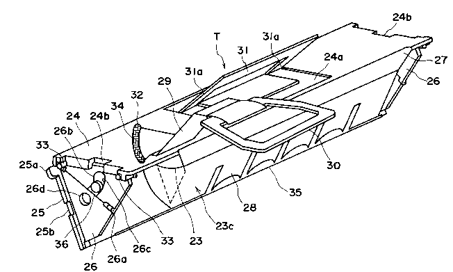
Figure 23 is an external perspective view of
the image forming apparatus illustrated in Figure 22.
2173196
--10--
Figure 24 is a sectional view depicting the
structure of a typical process cartridge installable
in the image forming apparatus illustrated in Figure
22.
Figure 25 is an external perspective view of
the process cartridge illustrated in Figure 24.
Figure 26 is a perspective view of the
portion of the main assembly of an image forming
apparatus, where the process cartridge illustrated in
Figure 25 is installed.
Figure 27 is a perspective view, as seen from
an angle different from the angle in Figure 26, of the
portion of the main assembly of an image forming
apparatus, where the process cartridge illustrated in
Figure 25 is installed.
Figure 28 is an explanatory drawing depicting
components related to the installation of the process
cartridge illustrated in Figure 25.
Figure 29 is a sectional view of the member
illustrated in Figure 28.
Figure 30 is a perspective view of the toner
cartridge in the second embodiment of the present
invention.
Figure 31 is a sectional view of the toner
cartridge illustrated in Figure 30.
Figure 32 is a perspective view of a process
cartridge in which the toner cartridge illustrated in
2173196
Figure 30 is inserted.
Figure 33 is an explanatory drawing depicting
the side plate of the toner cartridge illustrated in
Figure 30.
Figure 34 is a perspective view of the toner
cartridge in the third embodiment of the present
invention.
Figure 35 is an explanatory drawing depicting
a state in which the toner cartridge illustrated in
Figure 34 is in the process cartridge.
Figure 36 is a perspective view of a process
cartridge having a air discharge opening according to
an embodiment of the present invention.
Figure 37 illustrates a process cartridge
having the air discharge opening in an initlal state.
Figure 38 illustrates a process cartridge
having the air discharge opening when a first toner
cartridge is inserted.
Figure 39 illustrates a process cartridge
having the air discharge opening when a first toner
cartridge has been inserted.
Figure 40 illustrates a process cartridge
having the air discharge opening in a sealed state.
Figure 41 illustrates a process cartridge
having the air discharge opening when a first toner
cartridge has been positioned in proper place.
Figure 42 illustrates a tear tape when it is
2173196
-12-
being removed from the process cartridge having the
air discharge opening.
Figure 43 illustrates a process cartridge
having the air discharge opening when a second toner
cartridge is inserted.
Figure 44 is a perspective view of a process
cartridge having a air discharge opening according to
an embodiment of the present invention.
Figure 45 lS a sectional view of a process
cartridge having a air discharge opening of Figure 44.
DESCRIPTION OF THE PREFERRED EMBODIMENTS
Hereinafter, the electrophotographic image
forming apparatus, a process cartridge, a refill toner
container (hereinafter, toner cartridge), which are in
accordance with the present invention, will be
described with reference to the drawing.
First, referring to Figures 22 - 29, a
typical electrophotographic image forming apparatus
capable of accommodating the process cartridge in
accordance with the present invention will be
described.
As for the order of the descriptions, the
general structures of the image forming apparatus and
the process cartridge will be described first, and
then, the refill toner container will be described.
{General Structure}
217319~
-13-
Referring to Figures 22 and 23, this image
forming apparatus A is provided with an optical means
which comprises a rotary polygon mirror la, a lens lb,
and a deflection mirror lc. A light beam reflecting
image data is emitted from a laser light source, and
is projected by the optical means 1, to scan the
surface of a photosensitive drum 7 as the
electrophotographic photosensitive member. As a
resultl a latent image is formed on the surface of the
photosensitive member 7. This latent image is
developed into a toner image by a developing means 9
which uses toner.
In synchronism with the formation of the
toner image, a sheet of recording medium 2 is
delivered from a sheet feeder cassette 3a to an image
forming station of a process cartridge B by a sheet
feeding means 3 which comprises a pickup roller 3b,
conveyer roller pairs 3c and 3d, a registration roller
pair 3e, and the like, wherein the recording medium 2
is turned during the delivery. In the image forming
station, the toner image formed on the photosensitive
drum 7 is transferred onto the recording medium 2 by
applying voltage to a transfer roller 4 as a
transferring means.
After the toner image transfer, the recording
medium 2 is guided to a fixing means 5 by a guide
member 3f. The fixing means 5 comprises a fixing
- 21731~6
roller 5b containing a heater 5a, and a driving roller
5c which presses the recording means 2 on the fixing
roller 5b as well as advances it. As a result, the
toner image is fixed to the recording medium 2. Then,
the recording medium with the fixed toner image is
further conveyed through a turning path 3j, and
discharged into a discharge tray 6, by discharge
roller pairs 3g, 3h and 3i. Regarding the recording
medium discharge, a switchable flapper 3k may be
activated to discharge the recording medium 2 straight
forward by a discharge roller pair 3m, without sending
the recording medium 2 through the turning path 3j.
Next, referring to Figures 24 and 25, in the
process cartridge B containing the image forming
station, while a photosensitive drum 7 provided with a
photosensitive layer is rotated, a predetermined level
of voltage is applied to a charge roller 8 as a
charging means. As a result, the surface of the
photosensitive drum 7 is uniformly charged. Then, the
uniformly charged surface of the photosensitive drum 7
is exposed to the scanning beam projected from the
optical means 1 through an exposure opening lO. As a
result, the latent image is formed on the surface of
the photosensitive drum. The latent image is
developed by the developing means 9. It should be
noted that the charge roller 8 is in contact with the
photosensitive drum 7, being thereby rotated by the
-15- 2173I96
rotation of the photosensitive drum 7.
In the developing means 9, as a toner feeding
member 9b is rotated, the toner within a toner storing
portion 9a is sent toward the development roller 9c.
As the development roller 9c containing a fixed magnet
is rotated, a triboelectrically charged toner layer is
formed on the surface of the development roller 9c by
a blade 9d. The toner in this toner layer is
transferred onto the surface of the photosensitive
member 7 in correspondence to the aforementioned
latent image, whereby a toner image, that is, a visual
image, is formed on the photosensitive drum 7.
Next, a voltage with a polarity opposite to
the toner image polarity is applied to the transfer
roller 4, whereby the toner image is transferred onto
the recording medium 2. Thereafter, the toner
remaining on the photosensitive drum 7 is removed by a
cleaning means lO comprising a cleaning blade lO and a
waste toner collector lOb; the residual toner on the
photosensitive drum 7 is scraped off and collected
into the waste toner collector, by a cleaning blade
lOa, preparing the photosensitive drum 7 for the
following process. The cleaning blade lOa is in
contact with the photosensitive drum 7.
Various components such as the photosensitive
drum 7 are integrally disposed within a housing which
is formed by joining first a toner container 11 and a
2173Ig6
-16-
developing frame 12, and then, a cleaning frame 13; a
process cartridge B is formed. This process cartridge
B is removably installed in a cartridge accommodating
means provided within the main assembly 14 of the
image forming apparatus.
Next, referring to Figures 26 and 27, as a
lid 15 of the cartridge accommodating means is opened,
a cartridge accommodating space is exposed. A
cartridge accommodating member 16 (guide member) is
attached to each of the lateral walls of the apparatus
main assembly 14. Both the left and the right guide
members are provided with a guiding portion 16a. The
process cartridge B is inserted to follow the guide
portion 16a. Thereafter, the lid 15 is closed, ending
the sequence for installing process cartridge B into
the image forming apparatus A.
{Structure of Housing}
The housing of the process cartridge B in
this embodiment is formed by joining the toner
container 11, the developing frame 12, and the
cleaning frame 13. Below, the structure of the
housing will be described.
Referring to Figure 24, the toner container
is provided with a toner storing space 9a, in which
the toner feeding member 9b is disposed. The
development roller 9c and the developing blade 9d are
mounted in the developing frame 12. A stirring member
2173196
-17-
9e for circulating the toner within the development
chamber is rotatively mounted adjacent to the
development roller 9c. The toner container 11 and the
developing frame 12 are joined by welding to form a
developing unit D.
The photosensitive drum 7, the charge roller
8, and the cleaning means lO are mounted in the
cleaning frame 13, and then, a drum shutter 18 is
attached to the cleaning frame 13, completing a
cleaning unit C. When the process cartridge B is
removed from the apparatus main assembly 14, the drum
shutter 18 covers the photosensitive drum to protect
it.
Next, the development unit D and the cleaning
unit C are joined to form a process cartridge B. Each
longitudinal end of the developing frame 12 is covered
with an unillustrated cover member which rotatively
supports the correspondent end of the development
roller 9c. This cover member is provided with an arm
19, and a rotational axis 20 is formed at the end of
the arm 19 as shown in Figures 28 and 29, which
illustrate only one side of the process cartridge B.
Further, at each longitudinal end of the
cleaning frame 13, a recess 21 for positioning the
rotational axis 20 is provided. The rotational axis
20 is inserted in this recess 21, and then, a joining
member 22 with a projection 22a is attached to the
2173196
-18-
cleaning frame 12 using a screw, whereby the
developing unit D and the cleaning unit C are joined
in such a manner that they become rotatable about the
rotational axis 20, allowing the development roller 9c
to be pressed onto the photosensitive member 7 by the
weight of the developing unit D itself.
Further, the developing frame 12 is placed
under the downward pressure from a compression spring
22b attached to the joining member 22, so that the
development roller 9c is reliably pressed toward the
photosensitive member 7. Further, an illustrated
spacer ring is mounted at each of the longitudinal
ends of the development roller 9c, and this ring is
pressed on the photosensitive drum 7, maintaining a
predetermined gap between the photosensitive drum 7
and development roller 9c.
Again, referring to Figure 25, the process
cartridge B is provided with a cover member 44 for
covering or exposing the opening. The substantially
central portion of the cover member 44 is provided
with a handhold portion 50 for making it easier to
open or close the cover member 44. Further, when the
toner cartridge is placed in the process cartridge B
with the cover member 44 closed, a tear tape handle
30, which is used to unseal the toner cartridge to
replenish the process cartridge B with the toner,
projects from the process cartridge. This will be
2173196
--19--
described in more detail later. It should be noted
here that the cover member 44 covers an opening 9g
provided at the top of the toner storing portion 9a,
and is openable when the toner is supplied into the
toner storing portion 9a.
Further, the process cartridge is provided
with a locking means 52 for locking the cover member
44. The locking means 52 is disposed at a location
adjacent to the handhold portion 50 of the closed
cover member 44. When the locking means 52 is rotated
upward and to the right, the cover member 44 is
unlocked becoming ready to be opened.
Further, the process cartridge B comprises
guides 54 and 56, which are located at each
longitudinal end of the process cartridge B, and are
used for installing the process cartridge B into the
image forming apparatus main assembly.
Next, the process cartridge B in accordance
with the present invention, and the toner cartridge C
in accordance with the present invention, will be
described.
Embodiment 1
Referring to Figures 1 - 3, a toner cartridge
T is substantially in the form of a triangular column,
and comprises a toner storing container 23 for
containing the toner, a top guide plate 24, a bottom
guide plate 25, and substantially triangular side
217319~
-20-
plates 26 and 26. The top and bottom guide plates 24
and 25 are holding means for holding the toner storing
container 23, and are held together at their
longitudinal ends by the side plates 26. In other
words, the toner cartridge T has a substantially
triangular cross section or a substantially
rectangular cross section.
Referring to Figures 4 - 6, the toner storing
container 23, which is a flexible container, is in the
form of a substantially triangular column, and
comprises a V-shaped main body section 23a for storing
the toner, wherein the portion equivalent to the open
end of the character V is an opening 23c. The toner
storing container 23 further comprises side wall
sections 23b located at each longitudinal end of the
main body section 23a, a flange 23d surrounding the
entire edge of the opening 23c, and a sealing member
for sealing the opening 23c. The sealing member will
be described later.
In the case of the toner storing container in
this embodiment 23, which is in the form of a
substantially triangular column as described before,
the side wall portion 23a and the portion 23dl of the
flange 23d are bent inward so that when the V-shaped
main body section 23a is pressed from the direction
perpendicular to the longitudinal direction of the V-
shaped main body section 23a after the completion of a
2173196
-21-
toner refilling operation, the side wall portion 23b
is reliably folded inward of the main body section 23a
(Figure 6). In other words, the center portion of the
portion 23dl of the flange 23d, and the center portion
of the side wall 23b, that is, the portion equivalent
to the vertical line 23bl drawn from the top vertex of
the triangular side wall 23d, are recessed.
Therefore, as seen from the opening 23c side, the both
side walls of the toner storing container 23
substantially look like a character M as illustrated
in Figure 5. That is, the inwardly projecting portion
23bl of the side wall portion 23b connects the center
portion of the longitudinal end edge of the opening
23c and the farthest vertex of the substantially
triangular side wall 23d from the longitudinal end
edge of the opening 23c; the inwardly projecting
portion 23bl of the side wall portion 23b can be
compared to the line connecting the pivot portion of a
fan to the center portion of the edge of the open fan.
As for the toner storing container material,
in order to assure that the toner storing container 23
is reliably collapsible with application of only a
small amount of pressure, soft material such as
polypropylene, polyethylene, vinyl chloride, nylon, or
the like is used. Further, in order to reduce the
wall thickness, the toner storing container 23 is
formed by vacuum molding. More specifically, a 0.6 mm
2173I9~
thick polyethylene-polypropylene laminate sheet was
used, and the wall thickness of the finished product
ranged from 0.2 mm to 0.6 mm. Also regarding the wall
thickness of the finished product, the thickness of
the side wall portion 23b and the portion 23dl of the
flange 23d are preferred to be in a range of O.1 - l.O
mm so that they can be easily collapsed with the
application of only a small amount of force. That is,
when the wall thickness is no more than O.l mm, it is
liable that a pin hole may develop, which is liable to
result in toner leakage; when it is no less than 1 mm,
compression strength is larger, making it difficult to
collapse the toner storing container 23.
The provision of the aforementioned structure
assures that the toner storing container is easily
collapsible or foldable with the application of only a
small amount of pressure.
The opening 23c of the toner storing
container 24 is sealed with a sealing member which is
fixed to the flange 23d using means such as gluing,
welding, or the like.
The sealing member may be formed of a plain
easy peel film such as one used for the conventional
toner storing container, but in this embodiment, a
tear tape unit illustrated in Figure 5 is employed to
reduce the tear resistance of the sealing member, that
is, to make it easier to unseal the toner storing
2173196
-23-
container. The tear tape unit comprises a cover film
27 for covering the opening 23c, and a tear tape 28
which is laid in contact with the cover film 27. The
rear tape 28 extends from one longitudinal end of the
opening 23c to the other end, partially covering the
opening 23c by a width defined by one of the
longitudinal edges of the opening 23c and a tear line
27a, and then, is folded back, being extended backward
beyond the starting point. With the provision of this
structure, the toner storing container can be unsealed
by pulling the end portion of the extended folded
portion 28a of the tear tape 28. This is, the cover
film 27 is torn along the tear line 27a by pulling the
extended folded portion 28a of the tear tape 28, and
is peeled away from the flange 23d. As a result, the
opening 23c is exposed to release the toner, though a
portion of the cover film 27 remains partially
covering the opening 23c.
In this embodiment, the configuration of the
toner storing container 23 is such that its cross
section is substantially triangular, but this
configuration is not mandatory. Instead, it may be
shaped like a toner storing container 23A illustrated
in Figure 7, that is, a toner storing container having
a cross section like a sector, which is accomplished
by modifying the side plates 26 in such a manner that
vertex portion of the side plate, and the edge
2173196
-24-
opposing the vertex portion, form an arc-like
configuration.
Again, referring to Figures 1 - 3, the end
portion of the tear tape 28 is provided with a tear
tape handle fixing plate 29, and a tear tape handle 30
is fixed to the tear tape handle fixing plate 29. The
tear tape handle fixing plate 29 is removably attached
to the top guide plate 24. When this tear tape handle
30 is pulled, the tear tape 28 is pulled. As a
result, the cover film 27 is torn along the tear line
27a, creating an opening 27b which permits toner
discharge. It should be noted here that the opening
27b is offset toward one of the longitudinal edges of
the opening 23c of the toner storing container 23.
The V-shaped toner storing container 23 is
provided with a top guide plate 24 and a bottom guide
plate 25, wherein these guide plates 24 and 25 are
mounted on the walls equivalent to the diagonal stroke
portions of the character V, using an appropriate
means. The top guide plate 24 is provided with an
arc-shaped guide hole 32 formed by drilling. It is
located adjacent to one of the longitudinal ends of
the top guide plate 24. The tear tape 28 is put
through this guide hole 32. The top guide plate 24 is
also provided with an insertion handle 31. which is
located on the top surface, at a substantially middle
portion in the longitudinal direction.
21 7319G
-25-
The insertion handle 31 makes it easier to
insert the toner cartridge C into the process
cartridge B. Referring to Figure 1, the insertion
handle 31 is a U-shaped single piece component formed
of a flexible resin material such as polypropylene
(PP) or polyamide (PA). Its thickness is 1 - 2 mm,
except for the base portion of the leg portion 31a or
31a. The base portion of the leg portion 31a is
rendered thinner than the rest, being 0.3 - 0.8 mm
thick, so that it becomes bendable enough to serve as
a hinge.
Because of the above construction, that is,
since the leg portion 31a of the insertion handle 31
is bendable at its bendable portion, the insertion
handle 31 can be disposed into a recess 24a which is
provided in the top surface of the top guide plate 24.
The recess 24a has a configuration matching that of
the insertion handle 31. The depth of the recess 24a
equals the thickness of the insertion handle 31;
therefore, when the insertion handle 31 is fitted in
the recess 24a, the outward facing surface of the
insertion handle 31 becomes level with the top surface
of the top guide plate 24, contributing to the saving
of space.
In the normal state, the insertion handle 31
diagonally sticks out from the top surface of the top
guide plate 24 so that it can be easily grasped.
217319&
-26-
Further, the top guide plate 24 is provided
with four guide rollers 33; two guide rollers 33 are
mounted on the surface of each longitudinal end,
extending in the longitudinal direction of the top
guide plate 24. These guide rollers 33 are fitted in
guide grooves of the process cartridge, which will be
described later, and regulate the position of the top
guide plate 24. On the downward facing surface of the
top guide plate 24, a wiping seal 34 is attached along
the edge of the guide hole 32.
At each longitudinal end of the toner storing
container, one of the edges of the side plate 26 is
rotatively connected to the downward facing surface
of the top guide plate 24.
Also at each longitudinal end of the toner
storing container, the other edge of the side plate 26
is rotatively connected to the upward facing surface
of the bottom guide plate 25.
The downward facing surface of the bottom
guide 25 is provided with a cover 35 which covers the
tear tape 28 along the longitudinal edge of the
opening 23c, so that when the toner cartridge C is
inserted into the process cartridge B, the tear tape
28 is prevented from being snugged.
Further, the bottom guide plate 25 is
provided with a projection 25a which is located at
each longitudinal end of the bottom guide plate 25, at
217319~
the corner opposite to the corner at which the cover
35 is attached, and projects in the longitudinal
direction of the toner cartridge C. This projection
25a also regulates the movement of the bottom guide
plate 25 in the same manner as the guide rollers 33 of
the top guide plate 24 when the process cartridge C is
inserted into the process cartridge B.
The side plate 26 is substantially
triangular, and is rotatively connected to the top
guide plate 24 and the bottom guide plate 25 by the
corresponding edges, respectively. It is provided
with a hinge portion 26a which perpendicularly extends
from the center portion, that is, the vertex portion,
to the edge opposing the vertex; therefore, it can be
folded inward.
Further, referring to the drawings, in
particular Figure 2, a slit 26b is provided across the
inward facing surface of the foldable portion of the
side plate 26. In the slit 26, a fan-shaped stopper
36 for preventing the side plate 26 from folding
inward is fitted. The stopper 26 is provided with a
claw 36a which engages with the stopper locking
portion 26bl or 26b2 of the slit 26b, and a columnar
projection 36b which is movable along an arc-like hole
formed by cutting the top guide plate side half of the
side plate 26.
Normally, the projection 26a of the stopper
2173Ig~
-28-
36 is in engagement with the first stopper locking
portion 26bl, that is, the stopper is positioned
across the foldable portion of the side plate 26,
preventing the side plate 26 from being folded.
However, when the stopper 36 is rotated counter-
clockwise, relative to the drawing, about an axis 36c
using the projection 36b, the engagement between the
projection 36a and the first stopper locking portion
26bl is switched to the engagement between the
projection 36a and the second stopper locking portion
26b2; the stopper 36 is retracted from the foldable
portion toward the top guide plate 24, allowing the
side plate 26 to be folded.
Further, the bottom guide plate side half of
the side plate 26 is provided with a round hole 26d
formed by drilling and having a diameter matching that
of the columnar projection 36b. When the side plate
26 is folded, the projection 36 loosely fits in the
hole 26d, not interfering with the folding of the side
plate 26.
Further, each longitudinal end of the top
guide plate 26 or the bottom guide plate 25 is
provided with a cutaway portion 24b or 25b,
respectively, for preventing the top or bottom guide
plate 24 or 25 from interfering with the spring member
of the process cartridge B, which will be described
later.
2173196
-29-
Next, referring to Figures 8 - 10, the
process cartridge B in accordance with the present
invention will be described again, this time in more
detail.
The opening 9g located at the top of the
toner storing portion 9a is exposed or covered by
opening or closing the cover member 44. The cover
member 44 has fan-shaped side plates 44a. The fan-
shaped side plate 44a is provided with an axial
projection 44b. The locatlon of the axial projection
is equivalent to the location of the pivot of a fan.
This axial projection 44b fits in a recess provided in
the outward facing surface of the exterior wall of the
toner storing portion 9a of the aforementioned process
cartridge B, whereby the cover member 44 is rotatively
connected to the process cartridge B.
On the back surface of the cover member 44, a
pusher projection 44d for pushing the toner cartridge
T into the toner storing portion 9a, and a guide rib
44e for guiding outward the tear tape 28, are
provided.
On the inward facing surface of the front,
rear, left, or right wall of the process cartridge B,
which surrounds the toner storing portion 9a, a
sealing member 37 made of MOLT PLANE, or the like
having a predetermined thickness is bonded. Also, on
the inward facing surface of the left or right side
2I 73196
-30-
wall, two guide grooves 38 for guiding the inserted
toner cartridge T, and a spring 39 for folding the
inserted toner cartridge T, are provided.
The guide grooves 38 form an arc by the
portion closer to the entrance for the toner cartridge
T, and strainghten toward the deeper end, wherein two
grooves 38 remain parallel to each other.
Referring to Figure 9, on the left and right
walls of the toner storing portion 9a, a first
engagement claw 40 is attached, which comprises a
central axial member 40a, and is rotatable about the
axial member 40a. The first engagement claw 40
further comprises a first projection portion 40b
extending outward from one end, and a second
projection portion 40c extending inward from the other
end; they extend in the opposite directions. Further,
the left and right side walls of the toner storing
portion 9a are provided with a window for allowing the
first projecting portion 40b to project outward. The
window 41 is covered from outside with a flexible
curtain 42. On the back surface of the second
projecting portion 40c, a spring 40d for pressing
inward the second projecting portion 4pc is mounted.
Referring to Figure 10, a second engagement
claw 43 is rotatively mounted on the inward facing
surface of the rear portion of the toner storing
portion 9a. The second engagement claw 43 also
2173196
regulates, along with the first engagement claw 40,
the movement of the inserted toner cartridge T. One
end of the second engagement claw 43 is pivotally
supported by an axial member 43a, and the inward side
of the other end is provided with a recessed
engagement portion 43b. On the back surface of the
engagement portion 43b, a spring 43c is mounted to
press inward the engagement portion 43b.
Further, adjacent to the opening 9g of the
toner storing portion 9a, a shield plate 45 is
located. This shield plate 45 keeps sealed the toner
initially stored within the process cartridge B, that
is, the toner is kept sealed when the process
cartridge B has never been used. The shield plate 45
is fixed by the first and second engagement claws 40
and 43. It has a structure equivalent to that of the
top guide plate 24, except for the lack of the
insertion handle 31 and the guide hole 32.
The toner stored within the toner storing
portion 9a never leaks out because it is sealed by the
shield plate 45 and the sealing member 37 bonded to
the front, rear, left, and right walls of the toner
storing portion 9a. Further, with the presence of the
shield plate 45, foreign matter, dust, or the like, is
prevented from mixing into the toner through the
opening during the toner refilling operation.
It should be noted here that the shield plate
2173196
-32-
45 is provided with guide rollers 33a at each lateral
edge, and can be moved inward of the toner storing
portion 9a by breaking its engagement with the first
and second engagement claws 40 and 43, and moving the
guide rollers 33a along the guide grooves 38 provided
on the side walls of the toner storing portion 9a.
Next, the toner refill related operations of
the process cartridge B and the toner cartridge T,
which are structured as described above, will be
described,
Referring to Figure 10, when the process
cartridge B is a new process cartridge, its internal
space (internal space of the toner storing portion 9a)
is full of toner, and the opening of the toner storing
portion 9a is shielded with the shield plate 45 at a
location D, that is, a location adjacent to the
opening of the lower storing portion 9a. The process
cartridge B in this state is inserted into the image
forming apparatus main assembly A, and is subjected to
an image forming operation, during which the initial
toner supply within the process cartridge B is
consumed.
Next, referring to Figure ll,.a case in which
the toner is refilled into the process cartridge B for
the first time using a toner cartridge T (first toner
cartridge T1) after the toner within the toner storing
portion 9a has been depleted as a result of the image
217319~
-33-
forming operation, will be described.
First, the lid 15 of the image forming
apparatus main assembly A is opened and the cover
member 44 of the process cartridge B is exposed.
Next, the cover member 44 is rotated about the axial
projection 44b, exposing the opening 9g of the toner
storing portion 9a. In this state, an operator grasps
the insertion handle 31 of the first toner cartridge
Tl, moves the first toner cartridge Tl to the location
above the opening of the toner storing portion 9a, and
places the first toner cartridge Tl into the opening
9g.
At this point, the first toner cartridge Tl
is oriented so that the vertex of the first toner
cartridge Tl, with reference to its section, is
located on the axial projection 44b of the cover
member 44, and the bottom guide plate 35 faces the
shield plate 45. Also at this point, the projection
25a projecting from the surface of the longitudinal
end of the bottom guide wall 25 is engaged with the
top guide groove 38 of the toner storing portion 9a.
The size of the bottom guide plate 25 of the
first toner cartridge Tl is set up to be smaller than
the size of the opening surrounded by the sealing
members 37 bonded on the lateral walls, the front
wall, and the rear wall, of the toner storing portion
9a. On the other hand, the size of the top guide
2173196
plate 24 is set up to be larger than the size of the
opening surrounded by the sealing members 37 bonded on
the lateral walls, the front wall, and the rear wall,
of the toner storing portion 9a, but smaller than the
size of the opening of the toner storing portion 9a
before the sealing member 37 is attached. Therefore,
as the first toner cartridge T1 is inserted through
the opening 9g, the bottom guide plate 25 is allowed
to pass through the opening 9g, but the top guide
plate 24 is stopped as it reaches the opening 9g.
In this state, the tear tape handle 30 of the
first toner cartridge T1 extends away from the toner
storing portion 9a because it is held by the tear tape
handle fixing plate 29 so as to project from the
cartridge T1.
Next, the cover member 44 is rotated in the
closing direction, whereby the pusher projection 44d
of the cover member 44 is placed in contact with the
top surface of the top guide plate 24 of the first
toner cartridge Tl. As the cover member 44 is further
rotated in the closing direction, the first toner
cartridge T1 is pushed into the process cartridge B
following the guide grooves 38, with t~e sealing
member 37 being compressed between the periphery of
the top guide plate 24, and the lateral, front and
rear walls of the toner storing portion 9a.
In this state, immediately before the top
21 73I96
-35-
surface of the shield 45 comes in contact with the
bottom surface of the bottom guide plate 25 of the
first toner cartridge Tl, the first projecting portion
40b of the first engagement claw 40 provided on the
outward facing surface of the side wall of the toner
storing portion 9a is pressed, along with the curtain
42, by the inward facing surface of the side plate 44a
of the cover member 44, as illustrated in Figure 9,
whereby the first engagement claw 40 is rotated
counterclockwise in the drawing about the axial member
40, breaking the engagement between the first
engagement claw 40 and the shield plate 45.
At the same time, the projection 43d of the
second engagement claw 43 provided at the top portion
of the rear wall of the toner storing portion 9a is
pressed by the edge portion of the bottom guide plate
25 of the first toner cartridge T1 as illustrated in
Figure 12, whereby the second engagement claw 43 is
rotated counterclockwise in the drawing about the
axial member 43 against the pressure from the spring
43c. As a result, the edge portion of the shield
plate 45 is disengaged from the recessed engagement
portion 43b, breaking the engagement between the
second engagement claw 43 and the shield plate 45.
Thereafter, the first toner cartridge T1 is
further inserted, with the guide rollers 33 of the top
guide plate 24 being engaged with the correspondent
217319~
-3~-
guide grooves 38 of the toner storing portion 9a. As
a result, the shield plate 45 is moved inward of the
toner storing portion 9a while remaining flatly in
contact with the bottom guide plate 24 of the first
toner cartridge Tl.
Referring to Figure 13, before the shield
plate 45 being moved inward of the toner storing
portion 9a along with the first toner cartridge T1
comes out of the sealing member region in which the
shield plate 45 remains in contact with the sealing
members 37 bonded to the lateral, front, and rear
walls of the toner storing portion 9a, the top guide
plate 24 of the first toner cartridge T1 comes in
contact with the sealing member 37 bonded to the
lateral, front, and rear walls of the toner storing
portion 9a; therefore, the sealed state of the toner
storing portion 9a is not interrupted. More
specifically, the sealing member 37 is bonded on the
lateral, front, and rear walls of the toner storing
portion 9a so as to cover inwardly from the opening of
the toner storing portion 9a far enough to seal the
edge of the shield plate 45 which is flatly in contact
with the bottom guide plate 25 of the first toner
cartridge T1. Further, when the first toner cartridge
Tl having been inserted through the opening 9g is in
the state illustrated in Figure 13, an arc b
connecting the top surface of the top guide plate 24
2173195
-37-
and the bottom surface of the shield plate 45 is
larger than an arc connecting the top surface of the
top guide plate 24 and the bottom surface of the
bottom guide plate 25; therefore, the sealed state of
the toner storing portion 9a can be maintained.
Next, the cover member 44 is completely shut
as shown in Figure 14. Regarding this state, the
height of the pusher projection 44d of the cover
member 44 is such that when the cover member 44 is
completely shut, the pusher projection 44 causes the
top guide plate 24 to engage with the first engagement
claw 40 (Figure 9) and the second engagement claw 43,
stopping the first toner cartridge T1 at a spot at
which the opening portion of the first toner cartridge
Tl faces downward to allow the toner to be easily
discharged.
In this state, the tear tape handle 30 is
pulled in the direction indicated by an arrow mark E
in Figure 15, that is, in the direction perpendicular
to the longitudinal direction of the toner storing
container 23, whereby the tear tape 28 is pulled in
the direction indicated by an arrow mark F, that is,
it is moved in the longitudinal direction of the toner
storing container 23, tearing the cover film 27
sealing the toner storing container 23, along the tear
line 27a, peeling off the bonded portion of the cover
film 27, and allowing the toner to discharge from the
21 73I96
first toner cartridge T1.
However, the flexible toner storing container
23 does not move together with the tear tape 28 as the
tear tape 28 is pulled because a hooking portion 23e
of the toner storing container 23 is hooked on the
projection 26e of the side plate 26, and the side
plate 26 is fixed by the stopper 36, which will be
described later.
The tear tape 28 is folded back through the
guide hole 3Z, and as it is pulled, the toner adhering
to the surface of the tear tape 28 is dropped into the
toner storing container 9a by the wiping seal 34. The
guide hole 32 is arc-shaped; therefore, the force
applied to pull the tear tape 28 in the direction of
an arrow mark E is caused to work to move the tear
tape 28 toward the center portion of the guide hole
32, preventing the tear tape 28 from displaced to one
side of the guide hole 32. Therefore, the occurrence
of the wrinkling of the tear tape 28, which prevents
smooth removal of the tear tape 28, can be prevented.
Next, referring to Figure 16, the tear tape
28 is folded back at the guide rib 44e of the cover
member 44, changing the direction toward the pull-out
direction G. Since the guide hole 32 (Figure 15) and
the guide rib 44e are formed so that the length m - n,
including the portion sticking out of the cover member
44, of one longitudinal edge of the tear tape 28
2173196
-39-
becomes substantially the same as the length p - g -
r, including the portion sticking out of the cover
member 44, of the other longitudinal edge of the tear
tape 28, the tear tape 28 can be pulled out in the
direction perpendicular to the longitudinal direction
of the process cartridge B.
The above structure allows the tear tape 28
to be pulled out with the cover member 44 of the
process cartridge B closed; therefore, the toner
refilling operation can be easily and smoothly carried
out.
Thereafter, the lid 15 of the image forming
apparatus main assembly 14 is closed. Thus, the toner
is refilled into the process cartridge B to restart
the image forming operation.
Next, a case in which the toner refilled by
the first toner cartridge Tl also has been depleted,
and toner is refilled a second time using another
toner cartridge (second toner cartridge T2) will be
described.
Referring to Figure 17, first, the lid 15 of
the image forming apparatus main assembly A is opened.
Then, the cover member 44 of the process cartridge B
is rotated in the opening direction, exposing the
opening of the toner storing portion 9a. Next, the
second toner cartridge T2 is inserted into the toner
storing portion 9a in the same manner as the first
2173196
-40-
toner cartridge Tl. Then, the cover member 44 is
rotated in the direction of the arrow mark in the same
manner as in the case of the first toner cartridge Tl,
whereby the top surface of the top guide plate 24 of
the second toner cartridge T2 is pressed inward of the
toner storing portion 9a by the pusher projection 44d
of the cover member 44.
At this point, the engagement of the first
toner cartridge Tl with the first engagement claw 40
and the second engagement claw 43 is broken in the
same manner as when the first toner cartridge Tl is
inserted into the toner storing portion 9a. As a
result, the first and second toner cartridges Tl and
T2 move together. The insertion handle 31 provided on
the top surface of the top guide plate 24 of the first
toner cartridge Tl is forced into the recess 24a
(Figure 1) of the top guide plate 24; therefore, the
top surface of the top guide plate 24 becomes flat.
Next, the bottom guide plate 25 passes by the
spring 29 (Figure 8) provided on the lateral walls of
the toner storing portion 9a, without interfering with
the spring 39, which is possible because the bottom
guide plate 25 is provided with the cutaway portion
25b (Figure 1). Then, the projection 36b of the
stopper 36 provided on the side plate 26 of the toner
cartridge Tl comes in contact with the spring 39.
At this moment, the stopper 36 receives the
2173I96
-41-
force from the spring 39 in the direction of an arrow
mark H as shown in Figures 18 and 19. The stopper 36
has been held immobile within the slit 26 as the claw
36a of the stopper 36 meshes with the first recess 26c
of the slit 26b (solid line), but upon receiving the
force from the spring 39, it is moved in the direction
of an arrow mark J, whereby the claw 36a engages with
the second recess 26d, holding the stopper 36 there
(dotted line). As a result, the side plate 26 is
rendered foldable as soon as the trailing end of the
moving stopper 36 passes the folding line.
Further, the projection 36b of the stopper 36
receives the force from the spring member 39 also in
the direction of an arrow mark I; therefore, the side
plate 26 is folded inward at the hinge portion 26a.
In this state, the first toner cartridge Tl has
already discharged the toner from the toner storing
container 23, allowing the side plate 26 to be easily
folded without any interference. As the side plate 26
2~ is folded inward, the projection 36b of the stopper 36
loosely fits in to the correspondingly drilled hole
26d (Figure 1). As a result, the folding of the side
plate 26 is not disrupted due to the interference
between the projection 36b and the side plate 26.
Thereafter, the top guide plate 24 passes by
the spring member 39 without interference, which is
rendered possible because the top guide plate 24 is
21731g6
-42-
provided with the cutaway portion 24b (Figure 1).
Then, the folded first toner cartridge Tl is moved
from the region in which the guide grooves 39 form
concentric arcs, to the region in which the guide
grooves 38 form parallel straight lines. As a result,
the top guide plate 24 and the bottom guide plate 26
become parallel, reducing the volume of the folded
first toner cartridge Tl to a minimum. It should be
noted here that even when vibrations or the like
unexpectedly occur during the folding of the side
plate 26, a rib 46 disposed on the inward facing
surface of the lateral wall of the toner storing
portion 9a in parallel to the guide groove 38
regulates the movement of the projection 36b of the
stopper 36; therefore, the side plate 26 which has
already begun to be folded does not return to its
initial state.
Next, toner is released into the process
cartridge B by pulling out the tear tape 28 of the
second toner cartridge T2 in the same manner as in the
case of the first toner cartridge Tl, and then, the
lid 15 of the image forming apparatus main assembly A
is closed to restart the image forming operation.
Thereafter, each time the refilled toner is
depleted, fresh toner can be supplied by inserting a
new toner cartridge. The preceding toner cartridges
are sequentially pushed inward and accumulated as a
2173196
-43-
new cartridge is inserted. In this embodiment, up to
four toner cartridges Tl, T2, T3 and T4 can be
inserted as shown in Figure 21.
As described above, the toner cartridge in
accordance with the present invention is foldable to
reduce its volume to a minimum, saving space.
Therefore, the toner cartridge in accordance with the
present invention can increase the number of toner
cartridges insertable in the toner storing portion 9a,
which in turn increases the amount of refillable
toner. In addition, it allows new toner cartridges to
e inserted in succession without a need for removing
the preceding one; therefore, it makes the toner
refilling operation a simple and easily understandable
operation, preventing the scattering of the toner.
Further, the sealing member having a proper thickness
is bonded to the inward facing surface of the front,
rear, and lateral walls of the toner storing portion
9a, making it possible to reliably prevent toner
leakage.
Further, according to the present invention,
the toner cartridge is given a substantially
triangular cross section, and is pushed into the
process cartridge following the arc-shaped guide.
Also, it is deformed to give it a rectangular cross
section having a smaller size than the initial
triangular cross section, and is accumulated along the
217~196
-44-
parallel guides. Therefore, the apparatus can be
downsized.
Further, one of the surfaces of the toner
cartridge in the form of a triangular column, where
the toner cartridge is to be unsealed to discharge the
toner into the toner storing portion, is oriented
downward as the toner cartridge is inserted following
the insertion path within the toner hopper.
Therefore, the toner within the toner storing
container can be reliably discharged.
Embodiment 2
Next, another type of a toner cartridge T
mounted in the process cartridge B in accordance with
the present invention will be described with reference
to Figures 30 - 33. Regarding the description of this
embodiment, only the portions different from those of
the toner cartridge T described in the first
embodiment will be described. The portions identical
to the those in the preceding embodiment will be given
identical reference numerals to omit their
descriptions.
Referring to Figures 30 and 31, the toner
cartridge T in this embodiment has a rib 24 which is
erected from the periphery of the top guide plate 24
of the toner cartridge T. In order to keep sealed the
toner contained in the toner storing portion 9a, it is
preferable that this rib 24 has a proper height for
2173196
-45-
providing a sufficiently wide contact area between the
toner cartridge T, and the sealing member 37 bonded to
the inward facing surface of the front, rear, and
lateral walls which surround the toner storing portion
9a of the process cartridge B. Also, it is preferable
that the rib 24 has a proper height for enabling the
bottom guide plate 25 of one toner cartridge T to be
fitted within the space surrounded by the rib 24c of
another toner cartridge T, and for sufficiently
reinforcing the top guide plate 24.
Each longitudinal end of the top guide plate
24 is provided with a cutaway portion 24b. The
cutaway portion 24b is located at a substantially
middle portion of the edge, and prevents the rib 46 of
the process cartridge B, which will be described
later, from interfering with the top guide plate 24.
THe bottom guide plate 25 is also provided with
cutaway portions 25b similar to the cutaway portion
24b.
Referring to Figure 33, a spring 47, that is,
an elastic member, is disposed at the joints between
the top and bottom guide plates 24 and 25, and the
side plate 26, pressing outward the side plate 26.
This arrangement prevents the side plate 26 from
folding inward, by resisting the force which normally
works to fold the top and bottom guide plate 24 and 25
toward each other.
21 731 9~
-46-
The top guide plate Z4 side half of the side
plate 26 is provided with a projection 48. The
projection 48 is located at a location correspondent
to the mid portion of the hinge portion 26a. Its
configuration is such that its height increases from
the hinge portion 26a toward the top guide plate 24.
Corresponding to the projection 48, the bottom guide
plate 25 side half of the side plate 26 is provided
with a hole 26d. The projection 48 is moved inward
toward the hole 26d as it is contacted by the rib 46
of the process cartridge B, which will be described
later, As a result, the side plate 26 becomes
foldable.
The toner cartridge in this embodiment is
simpler since it does not comprise the guide rollers
33 of the top guide plate 24, the projection 25a of
the bottom guide roller 25, and the stopper 36 of the
side plate 26, with which the toner cartridge
described in the first embodiment was provided.
Further, the process cartridge in this
embodiment does not comprise the guide groove 38
provided on the lateral walls surrounding the toner
storing portion 9a for guiding the ins~rted toner
cartridge T, or the spring 39 for folding the inserted
toner cartridge T, with which the process cartridge
described in the first embodiment was provided.
Instead, in this embodiment, only a rib 46 capable of
2I73196
-47-
offering the same function as the spring 39 is
provided on the lateral walls of the toner storing
portion 9a, extending from the deeper end toward the
entrance as illustrated in Figure 3Z.
Next, a toner refilling operation, in which
the process cartridge B structured as described above
is refilled with the toner from the toner cartridge T
described above, will be described.
The toner refilling operation in this
embodiment can be carried out in the same manner as
that in the first embodiment. First, the first toner
cartridge Tl is placed at the opening of the toner
storing portion 9a. Then, the cover member 44 is
rotated in the closing direction to place the pusher
projection 44 in contact with the top surface of the
top guide plate 24 of the first toner cartridge Tl.
Thereafter, the cover member 44 is further rotated in
the closing direction, whereby the first toner
cartridge Tl is pushed into the toner storing portion
9a following the side walls thereof while compressing
the sealing member 37 between the rib 24c of the top
guide plate 24 and the lateral, front, and rear walls
of the toner storing portion 9a.
After the shield plate 45 locked in the
initial state is unlocked as described in the
embodiment 1, the first toner cartridge Tl is pushed
further into the toner storing portion 9a, whereby the
2173196
-48-
bottom guide plate 25 of the first toner cartridge Tl
is placed flatly in contact with the shield plate 45.
Thereafter, the first toner cartridge Tl and the
shield plate 45 are moved together further into the
toner storing portion 9a.
Next, the cover member 44 is completely shut.
Then, the tear tape handle 30 is pulled, whereby the
cover film 27 sealing the toner storing container 23
is torn along the tear line 27a, and also, the portion
of the cover film 27 bonded to the flange is peeled
off, discharging toner from the first toner cartridge
T1.
Finally, the lid 15 of the image forming
apparatus main assembly A is closed. Thus, toner is
refilled into the process cartridge B, making it
possible to restart the image formation.
Next, a case in which the toner refilled by
the first toner cartridge Tl has been also depleted,
and toner is refilled a second time by the second
toner cartridge T2 will be described.
As described before, the second toner
cartridge T2 is inserted into the toner storing
portion 9a in the same manner as the first toner
cartridge T1, and then, as the cover member 44 is
rotated, the top surface of the top guide plate 24 of
the second toner cartridge T2 is pressed inward of the
toner storing portion 9a by the pusher projection 44d
2173196
-49-
of the cover member 44. As a result, the first toner
cartridge Tl is pushed inward with its top guide plate
24 being flatly in contact with the bottom guide plate
25 of the second toner cartridge T2.
After the first toner cartridge Tl is
released from its engaged state as it was in the first
embodiment, it is moved further inward of the toner
storing portion 9a. During this movement, the bottom
guide 25 of the first toner cartridge T1 can pass by
the rib 46 provided on the lateral walls of the toner
storing portion 9a without interfering with each other
because the bottom guide plate 25 is provided with the
cutaway portion 25b. Then, the projection 48 provided
on the side plate 26 of the toner cartridge T1 comes
in contact with the rib 46.
As the projection 48 provided on the side
plate 26 is pressed in the inward direction of the
toner cartridge Tl, the side plate 26 is folded inward
at the hinge 26a. During this side plate 26 folding
process, the projection 48 is loosely fitted into the
hole 26d correspondingly drilled in the side plate 26;
therefore, the folding of the side plate 26 is not
impeded by the projection 48 and the rib 46.
Next, the top guide plate 24 of the first
toner cartridge Tl passes by the rib 46, without
interfering with each other, which is possible because
the top guide plate 24 is provided with the cutaway
2173196
-50-
portion 24a. Then, the first toner cartridge T1 is
moved further into the toner storing portion 9a.
Next, toner is refilled into the process
cartridge B by pulling out the tear tape Z8 of the
second toner cartridge T2 in the same manner as
pulling the tear tape of the first toner cartridge T1.
Lastly, the lid 15 of the image forming apparatus main
assembly A is closed, and the image formation is
restarted.
Therefore, each time the refilled toner is
completely consumed, a fresh supply of toner can be
filled into the process cartridge B just by inserting
a new cartridge. The preceding cartridge are
sequentially compressed and accumulated by the
insertion of the following new toner cartridge. In
this embodiment, up to four toner cartridges T1, T2,
T3 and T4 can be inserted.
As for the state of accumulation, the shield
plate 45 is pushed into the deepest portion of the
toner storing portion 9a. The first to fourth toner
cartridges T1 - T4 are folded, forcing their top and
bottom guide plates 24 and 25 to be disposed in
parallel, and thereby reducing their volume. Also, as
the first to fourth toner cartridges Tl - T4 are
accumulated, the bottom guide plate 25 of the second
to fourth toner cartridges T2 - T4 is fitted into the
space surrounded by the rib 24c of the top guide plate
2173196
24 of the preceding first, second and third toner
cartridges Tl, T2 and T3, correspondingly, reducing
their collective volume.
As described above, the toner cartridge in
this embodiment is foldable to reduce its volume to a
minimum, saving space. Therefore, the toner cartridge
in this embodiment can increase the number of toner
cartridges insertable in the toner storing portion,
which in turn increases the amount of refillable
toner. In addition, it allows new toner cartridges to
be inserted in succession without a need for removing
the preceding one; therefore, it makes the toner
refilling operation a simple and easily understandable
operation, preventing the scattering of the toner.
Further, the sealing member having a proper thickness
is bonded to the inward facing surface of the front,
rear, and lateral walls of the toner storing portion,
making it possible to reliably prevent toner leakage.
Further, this embodiment can offer the same
effects as the first embodiment, using a simpler
structure than the first embodiment.
Embodiment 3
Next, the third embodiment of the toner
cartridge T usable with the process cartridge B in-
accordance with the present invention will bedescribed. Also in this embodiment, only the portions
different from those in the toner cartridge T
2173196
-52-
described in the first embodiment will be described,
whereas the same portions are designated by the same
reference numerals without descriptions.
Referring to Figure 34, the toner cartridge T
is substantially in the form of a triangular column.
Its structure is such that a toner storing container
23 containing toner is surrounded by a top guide plate
24, and two substantially rectangular side plates 26
rotatively connected, one for one, to the longitudinal
ends of the top guide plate 24, forming collectively a
U-shape. In other words, the structure of the toner
cartridge T in this embodiment is approximately that
of the toner cartridge T in the first embodiment minus
the bottom guide plate 25. Further, a stopper 56 is
provided on the top surface of the top guide pl~te 24,
adjacent to the cutaway portion 24. Similarly, the
shield plate 45 is also provided with a stopper 58.
Next, an operation for refilling toner into
the process cartridge B in accordance with the present
invention from the toner cartridge T in accordance
with the present invention will be described.
The operations of the process cartridge B and
the toner cartridge T during a toner refilling process
are substantially the same as those in the first
embodiment, except for a minor difference. That is,
since the toner cartridge T of this embodiment does
not have the bottom guide plate, the shield plate 45
2173196
-53-
is directly pushed at each longitudinal end by the
side plate 26 of the toner cartridge T. This will be
described next.
Referring to Figure 35, the side plate 26 of
the toner cartridge T is rotatively hinged to the top
guide plate 24 by the top edge, and the surface of the
bottom end of the side plate 26 is slanted so as to
cause the bottom portion to move outward upon
receiving pressure in the direction of the plane of
the side plate 26.
As the toner cartridge T with the above
structure is pushed into the toner storing portion 9a,
and the side plate 26 directly presses the shield
plate 45 at each end, the bottom end of the side plate
26 moves outward, the stops where it collides with the
stopper 58. In this state, the side plate 26 can
resist the force working to fold the side plate 26
inward; therefore, the toner cartridge T is moved,
together with the shield plate 45, inward of the toner
storing portion 9a, without collapsing.
Further, functions such as disengaging the
shield plate 45 or maintaining the sealed state of the
toner storing portion 9a which had to ~e carried out
by the bottom guide plate during the insertion of the
toner cartridge T in the preceding embodiment are
taken over by the top guide plate 24; therefore, the
lack of the bottom guide plate does not cause any
217~196
-54-
problem.
Thereafter, toner is discharged into the
process cartridge B by pulling out the tear tape 28,
with the cover member 44 of the process cartridge B
closed, making it possible to restart the image
formation, in the same manner as in the first
embodiment.
Next, a case in which the toner refilled by
the first toner cartridge T1 has been completely
consumed, and toner is refilled using the second toner
cartridge T2 having the same structure as the first
toner cartridge T1 will be described.
Also in this case, toner can be refilled
substantially in the same manner as in the first
embodiment, except for a minor difference. That is,
since there is no bottom guide plate in this
embodiment, the side plate 26 of the second toner
cartridge T2 directly presses the top guide plate 24
of the first toner cartridge Tl at each longitudinal
end. As the side plate 26 of the second toner
cartridge T2 directly presses the top guide plate 24
of the first toner cartridge T1, the side plate 26 of
the second toner cartridge T2 also is ~oved outward,
and stops where it collides with the stopper 56
provided on the top guide plate 24 of the first toner
cartridge T1, in the same manner as did the side plate
26 of the first toner cartridge Tl. In this state,
2I73I96
the side plate 26 of the second toner cartridge T2 can
resist the force working to fold inward the side plate
26; therefore, the toner cartridge T2 does not
collapse.
Thereafter, each time the refilled toner is
completely consumed, a fresh supply of toner can be
refilled by inserting a new toner cartridge. The old
cartridges are sequentially compressed and accumulated
by the insertion of a new cartridge.
Also in this embodiment, the same effects as
those descried in the first and second embodiments can
be obtained using the simpler structure.
Referring to Figures 36 - 45, the description
will be made as to a process cartridge having air
discharging means. According to he embodiments
described below, the toner scattering or blowing is
prevented when the cartridge is inserted into the
toner accommodating portion. Figure 36 corresponds to
Figure 8; Figures 37 - 41, to Figures lO - 14; Figures
42 and 43, to Figures 16 and 17; and Figures 44 and
45, to Figures 30 and 31, and therefore, the detailed
description thereof are omitted for simplicity.
As shown in Figure 36 - 45, the rearmost wall
of the toner accommodating portion 9a is provided with
an opening 9e. A air vent 47 is provided so as to
cover the opening 9e at the outside thereof. The air
vent 47 does not pass the developer particles but
21 731 9G
-56-
passes the air by the provision of a filter 47a having
a great number of pores or proper size.
By the provision of the air vent 47, the
blowing of the toner around the developing roller 9c
or the like in the toner accommodating portion 9a upon
insertion of the toner cartridge.
In this example, only one air vent is
provided, but a plurality of air vents can be provided
as shown in Figure 44, to increase the effects
thereof.
When the blocking plate 45 and the first
toner cartridge C is pushed into the rear side of the
toner accommodating portion 9a, the pressure on the
toner accommodating portion 9a is increased, and
therefore, the toner can be blown off through around
the developing roller 9c or the like. However, since
the air only is discharged through the air vent, the
pressure in the toner accommodating portion 9a is not
increased, so that the blowing of the toner can be
prevented with certainty.
Referring to Figure 45, another example of
the air vent may be described.
The air vent 57 comprises a filter 57a
mounted to cover an outer side of the opening 9f
formed in the rearmost wall of the toner accommodating
portion 9a, and a duct 57b, mounted to cover the
filter 57a, so as to prevent the blowing and
2173196
overflowing of the toner.
With this structure, the blowing of the toner
is first prevented by the filter 57a, and the even if
the filter 57a fails to prevent it, the duct 57a is
effective to prevent the toner. The duct 57b
constitutes a complicated path, more particularly, so-
called labyrinth. The outlet of the duct 57b is
provided with a second filter 57c of the same material
as the filter 57a, thus preventing the toner from
blowing off.
As will be understood from the foregoing,
according to the present invention, the toner supply
property can be improved. Further more, the toner can
be supplied without toner scattering. A volume of the
toner accommodating portion can be reduced in a
direction crossing with the longitudinal direction
thereof. Additionally, the toner blowing upon the
insertion of the toner supply container into the toner
accommodation container can be prevented.
In the preceding embodiments, the present
invention was described with reference to the cases in
which the toner cartridge in accordance with the
present invention was inserted into a process
cartridge. However, it is obvious that the toner
cartridge in accordance with the present invention is
usable with the toner hopper portion of an image
forming apparatus such as an electrophotographic
21 73I96
-58-
copying machine; it is usable with an apparatus which
does not comprise process units such as development
roller, and simply stores toner and supplies it to the
developing unit.
As is evident from the above description,
according to the present invention, it is possible to
provide a refill toner container easily collapsible
after the completion of a toner refilling operation,
and a process cartridge capable of accommodating such
a refill toner container.
Further, according to the present invention,
it is possible to provide a refill toner container,
the seal of which is removable with the process
cartridge closed, and a process cartridge capable of
accommodating such a refill toner cartridge.
Further, according to the present invention,
it is possible to provide a refill toner container
from which toner can be reliably filled into a toner
storing container through a simple toner refilling
operation, and a process cartridge capable of
accommodating such a refill toner container.
While the invention has been described with
reference to the structures disclosed herein, it is
not confined to the details set forth and this
application is intended to cover such modifications or
changes as may come within the purposes of the
improvements or the scope of the following claims.