Note: Descriptions are shown in the official language in which they were submitted.
WO 96105366 21 ~ 3 3 6 9 PCT/FI95/00424
1
A recovery boiler where the flue gas is divided
into two streams and a method therefore.
The present invention relates to a method of and an
apparatus for recovering energy and chemicals from waste
liquor in pulp processes. The invention especially
relates to an increase of the capacity of a recovery
boiler, i.e. kraft recovery boiler, or the like.
When combusting waste liquor in pulp processes, the aim
is to separate the organic and the inorganic parts of the
dry substance of the waste liquor from each other. The
heat from the organic part of the dry substance is
recovered and a largest possible amount of steam is
produced by means of this heat. Pulping chemicals are
recovered from the inorganic part of the dry substance in
such a form that they can, in the subsequent stages of
processing, be converted into a suitable form to be
reused in the cooking process.
The kraft recovery boiler has, until now, proved to be
superior for the recovery of heat and chemicals from
waste liquors. The recovery boiler prior to the main heat
absorbing sections can be considered as consisting of
three distinct zones: a reduction zone at the bottom of
the boiler, a drying zone, where liquor drops dry when
falling into the reduction zone, and an oxidation zone in
the upper section. The waste liquor is sprayed through
liquor nozzles in the form of small drops into a furnace
of the boiler. Combustion air is also introduced into the
recovery boiler. Air is usually introduced at three
different levels: primary air at the lower part of the
furnace, secondary air above the primary air level but
below the liquor nozzles, and tertiary air above the
liquor nozzles to ensure complete combustion. These three
air levels are conventional basic air levels in a modern
recovery boiler, but also other air levels may be
provided in said recovery boiler.
CO~IFIF~iVlATION COPY
2~~3369
-2-
METHOD OF AND APPARATUS FOR TREATING WASTE LIQUORS
The present invention relates to a method of and an apparatus for
recovering energy and chemicals from waste liquor in pulp processes. The
invention especially relates to an increase of the capacity of a recovery
boiler, i.e. kraft recovery boiler, or the like.
When combusting waste liquor in pulp processes, the aim is to separate the
organic and the inorganic parts of the dry substance of the waste liquor
from each other. The heat from the organic part of the dry substance is
recovered and a largest possible amount of steam is produced by means of
this heat. Pulping chemicals are recovered from the inorganic part of the dry
substance in such a form that they can, in the subsequent stages of
processing, be converted into a suitable form to be reused in the cooking
process.
The kraft recovery boiler has, until now, proved to be superior for the
recovery of heat and chemicals from waste liquors. The recovery boiler prior
to the main heat absorbing sections can be considered as consisting of three
distinct zones: a reduction zone at the bottom of the boiler, a drying zone,
where liquor drops dry when falling into the reduction zone, and an
oxidation zone in the upper section. The waste liquor is sprayed through
liquor nozzles in the form of small drops into a furnace of the boiler.
Combustion air is also introduced into the recovery boiler. Air is usually
introduced at three different levels: primary air at the lower part of the
furnace, secondary air above the primary air level but below the liquor
nozzles, and tertiary air above the liquor nozzles to ensure complete
combustion. These three air levels are conventional basic air levels in a
modern recovery boiler, but also other air levels may be provided in said
recovery boiler.
In the hot combustion chamber water vapor, volatile parts of the dry
substance, and eventually gasifiable parts of the dry substance evaporate
~1'~3369
-3-
from the liquor drops. The gases inflame, thereby delivering heat to heat
surfaces, a superheater and a boiler bank, disposed in the boiler and are
discharged from the upper end of the boiler. The ash from the waste liquor
drops, i.e. the inorganic substances of the waste liquor, accumulate on the
bottom of the boiler, from which they are removed and brought through
various stages of processing conveyed back to the cooking process.
The flue gases from the kraft recovery boiler contain a large amount of ash,
mainly sodium sulfate, a portion of which flows along with the flue gases
upwards in the boiler in the form of fine dust or molten drops. The salts
(Na2S04, Na2C03, NaCI) contained in the ash melt at a relatively low
temperature and become, when melting, easily adhesive and corrosive. The
deposits formed by the molten ash cause risk of clogging the flue gas
channels and, furthermore, cause corrosion and erosion of the heat surfaces
of the boiler. The risk of clogging and corrosion increases considerably the
number of shutdowns required for washing, inspection and maintenance.
A high temperature of the boiler tubes accelerates the formation of deposits
and thereby the corrosion risk of the heat surfaces. Thus, the deposits
affect particularly the heat surfaces of the superheater. Usually, the
corrosion of the materials is reduced by controlling the temperature of the
superheater surfaces.
The principal way of avoiding corrosion is, at least at the present, to choose
a sufficiently low temperature and pressure for the produced steam,
whereby the detrimental effects of the molten salt decrease. This means
that the steam cannot be superheated to as high a temperature as desired
for the production of electric power in steam turbine plants.
Attempts have been made to reduce fouling of surfaces and clogging of flue
gas channels by dimensioning the convection section large enough and
increasing the distance between the superheater surfaces. Larger clearances
facilitate cleaning of the surfaces. These arrangements increase, however,
A
2~~33~9
-4-
the size of the boiler and are thus, as regards the construction costs,
unfavourable.
A recovery boiler, in which the size of the superheater has had to be
increased, is, as regards the heat transfer and vaporization efficiency,
inferior to a corresponding coal-fired boiler. The tendency of the superheater
surfaces to foul multiplies the area of the heat surfaces needed in
comparison with a boiler, the flue gases of which contain only small
amounts or no ash at all.
The reactions in the furnace of the recovery boiler are usually not disturbed
by the amount of the black liquor to be treated. Consequently, the capacity
of the recovery boiler is mainly restricted by the fouling of the heat
surfaces
located in the upper end of the boiler. A new recovery boiler may be
required, if an essential increase in the amount of the black liquor to be
treated in the recovery boiler is desired, because the introduction of
additional heat surface in the existing recovery boiler is restricted from a
technical and economical point of view. However, the installation of the
new boiler would be an expensive solution.
It has been suggested that the recovery capacity of a pulp mill may be
increased by installing a so called recovery booster without necessitating
the construction of a new recovery boiler. The recovery booster is a
gasification or combustion unit installed outside the recovery boiler. The
idea is to bypass a portion of black liquor to this recovery booster and thus
reduce the load in the recovery boiler. The recovery booster of gasification
type operates with a principle of gasifying the black liquor at
substoichimetric condition resulting in a flue gas having a temperature of
about 800-900~4C. The flue gas is quenched with water and reduced
sulfurous components are scrubbed from the cooled gas by using a weak
caustic solution. The cleaned gas is then combusted in a separate gas
boiler. This solution may be technically satisfactory, but it requires rather
~1 ~3~6g
-5-
high initial investments. Additionally, the installation of this booster in an
old
pulp mill may be problematic because of lack of space.
The purpose of the present invention is to provide a method of increasing
the production capacity of a recovery boiler, even of an existing one, for
waste liquor in a technically simple and practical manner and more
economically than the previous methods.
In order to achieve the above mentioned objects, the method in accordance
with the present invention comprises the following steps:
(a) injecting waste liquid at a given level in the furnace of a recovery
boiler
and combusting waste liquor to generate flue gases;
(b) dividing the flue gases at least into two streams:
(c) introducing one of the streams through the furnace to the heat exchange
surfaces subsequent to the furnace of the recovery boiler and discharging it
from the boiler; and
(d) withdrawing the otherls) of the gas streams from the furnace at one or
more points located above the injection level for waste liquor and cooling
the discharged gas.
A characterizing feature of an apparatus, a recovery boiler, in accordance
with the present invention is that at least one conduit has been provided
above the waste liquor injection level for the discharge of a portion of the
flue gases from the furnace of a recovery boiler.
According to the present invention the capacity of the existing recovery
boiler may be increased considerably. A portion of the flue gas stream is
discharged from the furnace and thus the total volume of the gas stream
flowing to the boiler section is reduced. The method may lend itself to any
recovery boiler configuration.
As mentioned above, when the capacity of the boiler has to be increased,
the bottleneck in a recovery boiler is the boiler section, and not so much the
~~33fi9
-6-
furnace. By using the present invention, the capacity of the recovery boiler
may be increased in a very simple way by leading an extra amount of the
generated gas stream outside the recovery boiler so that this amount does
not have to flow to the heat exchange surfaces subsequent to the furnace
section.
The extra gas stream is discharged from the furnace of a recovery boiler at
a point where the conditions are preferably oxidative and thus the gases
contain hardly any uninflammable components. Such a zone is located
between the tertiary air level and a so-called nose, when air is introduced
into a boiler at three different levels: primary and secondary air below the
liquor nozzles and tertiary air above the nozzles to ensure complete
combustion.
The portion of the flue gas that corresponds to or is slightly greater than
that generated in the increase in the capacity of the recovery boiler may be
separated from the total flue gas stream and withdrawn from the boiler
upstream of the upper part of the boiler. Thus the gas amount flowing to
the heat surfaces located downstream of the furnace may be restricted to
the level prior to that increasing of the capacity or even below the level. No
heat surfaces downstream of the furnace in an existing recovery boiler have
to be changed because of the increased capacity.
The exhausted gas may in principle be cooled by means of any boiler
structure, which is applicable for treating this kind of unclean gas.
Preferably, the gas is cooled in a circulating bed reactor. The flue gas
withdrawn from the furnace is brought into contact, prior to a heat
exchanger, with solid particles which are separated from the cooled gas
after the treatment and recirculated back to the reactor. The gas may be
cooled below the solidification temperature so that the ash components
contained in the gas do not stick on the heat transfer surfaces. The ash
contained in the flue gases is preferably used as a circulating material. Some
~~73369
_7_
other inexpensive inert material, such as A1203, might of course be used, but
it is obviously most preferable to utilize material coming from the process.
Applicable circulating bed systems are described, for example, in GB patent
2,140,144 and in US patents 4,738,835 and 5,032,143. The use of the
circulating bed cooler brings about many advantages.
The majority, about 90%, of the solid matter (ash) contained in the flue
gases withdrawn 'form the furnace can be removed. Thus the ash content of
the exhaust gas from the cooler is rather low, and the gas may be
introduced along with the gas being discharged from the boiler section of
the recovery boiler into an electric precipitator thereof. Usually the
precipitator is able to receive the increased ash stream caused by the gas
stream from the circulating bed cooler. The increase in the ash stream is so
insignificant that it has usually no effect on the performance of the
precipitator.
Additionally, the space required by the circulating bed cooler is small in the
conditions prevailing in the recovery boiler plant. It is easy to install the
cooler to the immediate vicinity of the recovery boiler, even inside the
boiler
room. This is because the recovery boiler plant has space in the vertical
direction, but not in the latitudinal direction, and the space required by the
cooler is in the horizontal plane small compared with a cooler of another
type. The vertical space required by the circulating bed cooler does not
prevent the installation of the cooler in a recovery boiler plant.
The circulating bed cooler may be constructed into a steam boiler or a feed
water preheater. It may also serve as an air preheater, if it is reasonable
from a technical point of view. The construction for a steam boiler may be
made at least in the following ways:
the pressure in the steam boiler is the same as that in the recovery boiler.
Consequently, it is possible to use heat recovered form the cooler for the
'~1~3369
_8_
production of electric power. This construction is a so-called water-tube
boiler.
- the pressure in the steam boiler is the same as that in a steam system of a
pulp mill (bled steam or back-pressure, usually 10-12 bar and 2-5 bar,
respectively). This construction is, as regards the construction costs,
inexpensive. It is a so-called fire-tube boiler, in which a mixture of
circulating material and flue gases flows through vertically disposed tubes
and water to be vaporized outside the tubes.
The exhaust gas from the cooler is led through a connecting pipe to an
entry duct of the precipitator or to a separate ash separator, if any.
The invention will now be described more in detail with reference to an
accompanying drawing, in which one embodiment of the process according
to the present invention is schematically illustrated.
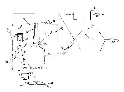
A conventional recovery boiler 10 in accordance with FIG. comprises a
furnace 12 and heat exchange surfaces subsequent to the furnace: a
superheater 14, a boiler bank 16 and an economizer 18, also referred to as
"heat exchange surfaces." In the combustion process, a char bed of dried
and partly combusted black liquor is formed at the bottom of the recovery
boiler. Molten chemicals flow through the porous char bed to the bottom,
from where they are transferred via melt spouts 22 to a dissolving tank (not
shown in the figure). Black liquor is introduced in the boiler by spraying
through nozzles 24. Combustion air is introduced from three different levels:
primary air 26, secondary air 28 and tertiary air 30. There may also be other
air feed levels in addition to those mentioned above.
In the recovery boiler heat is recovered from flue gases by means of
vaporizing surfaces 16 (boiler bank), a water preheater 18 (economizer) and
superheating surfaces 14. The flue gas that flows through the upper part of
the boiler is discharged from the boiler through a line 32 to an electric
precipitator 34.
_. -9- ~~73369
According to the invention, a portion of the flue gases formed in the furnace
of the recovery boiler exhausted from the furnace at a point located above
the injection level 24 for the liquor. This zone is situated between the waste
liquor injection level 24 and a nose 36, preferably above a tertiary air level
30. Thus the gas does likely not contain any significant amounts of
uninflammable components. Accordingly, the amount of the black liquor to
be fed to the recovery boiler (i.e. the capacity of the recovery boiler) may
be
increased, since part of the generated flue gas bypasses the upper end of
the boiler. The capacity of the boiler may thus be increased for at least 10-
30%.
Gas may also be discharged through the section above the nose 36, before
the gases flow to the superheaters 14.
In a system according to the present invention gas may be discharged
through at least one point, which are at the same level in the boiler wall.
Alternatively, discharge points may be located at different vertical levels.
For example, the most preferred arrangement depends on the lay-out of the
boiler plant.
The exhausted flue gas is introduced through a line or conduit 38 into a
cooling unit, also referred to as a "circulating bed cooler" 40, which
comprises a mixing chamber 42 and a heat exchanger 44. Such a cooling
unit is described, for example, in the above mentioned GB and US patents.
The flue gases are mixed with a cooled circulating material from a line 46,
which material preferably contains the ash in the gas. The temperature of
the mixture is decreased below the solidification temperature of the ash
components. After the mixing and the decrease of temperature the mixture
flows through a heat exchanger 44, whereby it is cooled. Since the
temperature is below the solidification point, the ash contained in the gas
does not stick on the heat surfaces. The heat exchanger may be
A
~'~~~36~
-10-
constructed as a steam boiler, a feed water preheater or an air preheater, as
described above.
After the heat exchanger, the gas is tangentially led through a line 48 to a
cyclone separator 50, in which the solid circulating material will be
separated from the gas. The purified gas in introduced through a line 52 to
the electric precipitator or to a separate ash separator 54. Part of the solid
material (ash) separated in the cyclone is returned to the mixing chamber 42
by means of the return pipe 46. The extra ash which cannot be used as a
circulating material is led through a line 56 to the existing ash system of
the
recovery boiler.
Part of the purified cooled gas may be circulated to the mixing chamber in
order to intensify the cooling.
While the invention has been described in connection with what is presently
considered to be the most practical and preferred embodiment, it is to be
understood that the invention is not to be limited to the disclosed
embodiment, but on the contrary, is intended to cover various modifications
and equivalent arrangements included within the spirit and scope of the
appended claims.