Note: Descriptions are shown in the official language in which they were submitted.
2173537
DEVICE AND ARRANGEMENT FOR USE IN PROCESSING CELLULOSE
SOLUTIONS
The present invention is concerned with a device for
controlling pressure in a flowing viscous mass and an
arrangement for the production of cellulose moulded bodies.
In particular, the present invention is concerned with a
device for controlling pressure in a flowing, highly viscous
cellulose solution, such as a mouldable solution of cellulose
in a tertiary amine-oxide, which is transported from a
solution production unit to a forming tool.
In order to produce fibres, films or other moulded bodies
from a starting material such as a polymer solution or
thermoplastic resin in a continuous manner and constant high
quality, it is not only necessary that the chemical/physical
properties of the starting material remain unchanged, but
also that at the forming tool, that is to say at the
spinneret or film extrusion head, the same conditions always
prevail. For this purpose, the uniformity of the spinning
pressure is of vital importance. At normal operation of an
industrial-scale arrangement, this condition will be usually
fulfilled, but if in some cases starting material is diverted
or withdrawn before reaching the forming tool, e.g. when
backwashing a filter or for some other purpose, the spinning
pressure naturally will drop. In this case, appropriate
devices for the compensation of the diverted starting
material must be provided in order to avoid a drop of the
pressure. Such a device is known for instance from AT-B 397
043, which will be described in more detail below.
On the other hand, it may occur that the feeding of starting
material to the forming tool has to be interrupted
altogether, for instance in order to exchange the forming
tool. Such an interruption however should not affect the
production of the starting material, since stopping and
restarting the production process involves the risk of
temporarily not being able to assure the constant quality of
the starting material. Thus it is necessary, so as not to
have to interrupt the continuous production of starting
2173597
material, to provide some kind of reservoir able to take up
the starting material produced during the period of time in
which no starting material can be processed by the forming
tool. Such a device is known from W0 94/02408, which will be
described in more detail below.
From GB-A - 841,403, a device is known by which a viscous
material such as margarine can be delivered intermittently.
This device has a cylindrical reserve chamber in which a
piston moves, delivering the margarine in portions. The
margarine is pushed into the reserve chamber in opposite
direction to the front of the piston, diverted and delivered
intermittently in the opposite direction. It is not mentioned
whether such a device is also appropriate for the continuous
delivery of a highly viscous material.
From DE-A - 3 416 899, a decorating machine capable of
applying e.g. a chocolate mass to biscuits is known.- Between
the spraying nozzles on the one hand and a pump for the
chocolate mass on the other hand, a cylinder is provided, a
pneumatic cylinder acting on the piston of the former. Thus a
uniform delivery of the chocolate mass from the spraying
nozzle, independently of the pressure variations caused by
the pump, is attained.
In some cases however, the device for controlling the
magnitude of a mass flow and the compensation of pressure
variations in a flowing, highly viscous mass is required to
fulfill yet another condition: it must not exhibit any
clearance volumes where starting material can accumulate.
This is of special importance when the the properties of the
starting material gradually change. Viscous polymer solutions
or thermoplastic materials of one or more polymers generally
have to be processed at elevated temperature. In such cases,
it may occur that the polymer has, at the elevated
temperature, only insufficient stability and is subjected to
degradation reactions. These degradation reactions possibly
may have even explosive character, thus representing a safety
21735~7
risk. These problems will be described in the following in
more detail by means of Examples of solutions of cellulose in
tertiary amine-oxides. For a general description of the
production of solutions of cellulose in aqueous tertiary
amine-oxides refererence is made to US-PS 4,196,282. In the
following "NMMO" (=N-methylmorpholine-N-oxide) will be used
instead of the term "tertiary amine-oxides".
The dissolution of cellulose in NMMO results in a partial
degradation of the polymer cellulose chain. This partial
degradation has a negative effect on the spinning security
and on certain properties of the finished products, such as
fibre strength, fibre elongation and loop strength.
Further it is known that cellulose solutions suffer gradual
discolouring due to the degradation of the amine-oxids used.
For instance, the monohydrate of NMMO is present under normal
conditions as a white crystalline solid, which melts at 72C.
When heating the monohydrate, strong discolouring will occur
from 120/130C up. From 175C up, an exothermal reaction is
triggered off, the melted mass being completely dehydrated
and great amounts of gas developing which eventually lead to
an explosion, the temperatures rising to far over 250C. It
is known that metallic iron and copper and particularly their
salts significantly reduce the decomposition temperature of
NMMO, while the decomposition rate is simultanously
increased.
Additionally to the problems mentioned above, there is
another difficulty, i.e. the thermal instability of the
NMMO/cellulose-solutions themselves. This means that at the
elevated processing temperatures (approximately 110-120C),
uncontrolable decomposition processes are triggered off in
the solutions which due to the development of gases may lead
to strong deflagrations, fires and even explosions.
In the literature, little is known about the correlations of
the thermally unstable nature of the solution, that is to say
21735~7
--4--
the extrusion mixture. Particularly when metal ions are
present, in certain cases a running-away of the decomposition
reactions in the dope may occur. The presence of metal ions
in the solution however can never be completely discarded due
to the metal construction of the arrangement components,
conveniently made of stainless steel.
Up to now, in the literature there has not yet been described
a stabilisation measure capable of sufficiently stabilising
cellulose and NMMO as well as reducing the thermal
instability of the cellulose/NMMO-solution to such an extent
that the explosive decomposition under process conditions may
be avoided. It is evident that particularly the thermal
instability of heated dopes is problematic, since in
arrangement components having greater capacities such as
buffer vessels, stirring vessels, mixing machines etc., these
dopes represent a safety risk.
In order to control the explosion risk during the production
of the solution and keep the thermal load on the solution
low, it is known from EP-A - 0356 419 to prepare the solution
in a thin film treatment apparatus instead of in a stirring
vessel or similar devices. In this process, the suspension of
cellulose in NMMO, the NMMO having a water content of up to
40%, is spread as a layer along the heated surface of the
Thin film treatment apparatus and transported, being exposed
to elevated temperature and reduced pressure, in order to
remove water until the cellulose dissolves. Thus it is
possible to rapidly heat the suspension to the temperatures
necessary for the preparation of the solution in an
economical way, and simultaneously to rapidly prepare the
solution so as to avoid to a great extent a decomposition of
the tertiary amine-oxide and a decomposition of cellulose.
Moreover, the safety risk, compared to the preparation of the
solution in a stirring vessel, is significantly reduced,
since the solvent is not heated in a large amount at once,
but only in comparatively small amounts.
2173597
-5-
Thus the process described in EP-A - O 356 419 reduces the
safety risk occurring during the production of the cellulose
solutions by technical measures. There is however still a
risk of degradation of the cellulose and NMMO and exothermal
reactions, deflagrations etc., when the finished solutions
are processed, i.e. in the arrangement components provided
between the thin film treatment apparatus and the forming
tool. Such arrangement components include buffer or reserve
vessels which for instance are disposed between a filter
device which can be backwashed and the forming tool, in order
to avoid as far as possible discontinuities in the flow of
the dope towards the spinning machine when changing the
filter or backwashing.
As mentioned above, such a filter device which can be
backwashed having a reserve vessel joined thereto is known
from AT-B 397 043. This device has been developed for a
thermoplastic synthetic material and has a case in which two
adjustable screen supporting members are arranged between an
operation position and a backwash position. In the backwash
position, the screen to be backwashed is downstream in open
connection with the downstream side of the screen being in
operating position. A narrow cylindrical reserve chamber
having T-shape, in which a piston moves, is joined to the
common discharge channel leading to the spinning machine.
Before starting the backwash process, the piston is slowly
withdrawn, whereby synthetic material is slowly diverted from
the discharge channel. Conveniently, the synthetic material
is diverted at such a reduced rate that no significant
pressure drop occurs at the spinning machine. When the
reserve vessel is filled with melted mass, the screen
supporting member carrying the screen to be backwashed is
changed to backwash position and backwashing is carried out
by means of the piston such that the pressure at the spinning
machine is at least approximately maintained.
This known device has the drawback that it is only able to
immediately compensate a rapidly occurring pressure drop in
- 2173~7
--6--
the discharge channels if a certain amount of synthetic
material is always present as a reserve in the cylindrical
reserve chamber, which when required can be delivered by the
piston immediately to the discharge channel. Naturally, this
reserve material remains for hours in the cylindrical reserve
chamber, being subjected during this time to various
degradation reactions occurring on the cellulose and the
NMM0. These degradation products contaminate the dope.
Moreover, during its residence in the cylindrical reserve
chamber this reserve material is contacted with a relatively
big metal surface, since the lengthtwidth-ratio of the
reserve chamber is high, whereby an enrichment of metal ions
at the contact surface to the cellulose solution is promoted.
These metal ions may trigger off a thermal running-away of
the decomposition reactions up to the point of an explosive
decomposition.
WO 94/02408 is concerned with a process for storing a liquid,
highly viscous medium in a tank having an adjustable
capacity. This storage tank is disadvantageous for mouldable
solutions of cellulose in tertiary amine-oxides for two
reasons. First, in a continuous process for the production of
cellulose objects, storing of starting material, i.e. the
thermally unstable cellulose solution, in a tank should be
avoided altogether. As mentioned above, during the residence
time of the cellulose solution the cellulose and the tertiary
amine-oxide are subjected to degradation, the products of
which deteriorate the quality of the moulded bodies. Second,
in the proposed tank a continuous passing of the highly
viscous solution is not ascertained due to its complex
configuration. In consequence, a flow profile is formed with
areas where one part of the cellulose solution flows more
quickly than other parts.
When the tank for highly viscous cellulose solutions
described in W0 94/02408 is employed, this flow profile is so
pronounced that at some sites the cellulose solution flows
only very slowly or not at all. This is disadvantageous,
21735~7
-
--7--
since not only the residence time of the thermally unstable
solution is increased, but also because cellulose solution
accumulates at some sites, so-called clearance volumes, and
is enriched with metal ions due to its contact with metal
surfaces, increasing the risk of an intense decomposition
reaction.
Ideally, a device for controlling pressure in a flowing,
highly viscous cellulose should be such that the solution,
when passing the device, is passed on uniformly like a plug,
not adopting any flow profile.
Thus it is the object of the present invention to provide a
device for controlling pressure in a flowing viscous mass
fulfilling the following conditions:
1. the device must be able to respond immediately to a
pressure drop, compensating with additional starting
material; this starting material however must not have
been diverted before from the main stream, as is the
case in the device according to AT-B 397 043;
2. the device should not have any clearance volume where
starting material can accumulate;
3. the device must have a simple configuration and be
simple to operate;
4. the device must be designed such that the residence time
of the starting material in the device is as short as
possible, i.e. that a flow profile according to which
part of the viscous mass is transported at a
significantly lower rate is avoided; and
5. the device must be designed such that the starting
material has as little contact as possible with metal
surface.
The device according to the invention for controlling
pressure in a flowing viscous mass is characterized by:
- an inlet through which the mass flows into the device,
2173597
- a guiding element having a receiving capacity for the
mass flowing from the inlet,
- a piston having an aperture, which piston is movable
within the guiding element, the receiving capacity of the
guiding element being varied by moving the piston,
- a receptacle attached to said aperture at said piston and
joined-to the inlet, so that the flowing mass passes from
the inlet through the receptacle and the aperture of the
piston into the guiding element,
- an outlet into which the guiding element leads and by
means of which the flowing mass is delivered from the
device,
provided that the inlet, the guiding element and the
receptacle are designed in a pipe-shape and that the
receptacle slides over the inlet like a telescope when the
piston is moving.
A preferred embodiment of the device according to the
invention consists in that the piston is joined to a static
mixer being movable in the guiding element and moving
together with the piston.
Preferably, the guiding element has a pressure chamber into
which a fluid such as a gas or a hydraulic oil which is
pressurized and able to move the piston may be introduced
through an aperture.
It has been shown that the device according to the invention
is particularly appropriate for use in the processing of
cellulose solutions. Thus the invention is also concerned
with the use of the device according to the invention in
processing mouldable cellulose solutions, wherein as the
mouldable cellulose solution particularly a solution of
cellulose in an aqueous NMMO is used.
Further, the invention is concerned with an arrangement for
the production of cellulose moulded bodies, said arrangement
comprising:
2173537
- a mixer wherein a suspension is produced from shredded
cellulose and an aqueous solution of a tertiary amine-
oxide,
- a thin film treatment apparatus, which is joined to the
mixer by means of a pipe and wherein by using the thin-
film technique water is evaporated from the suspension at
elevated temperature and reduced pressure until a
cellulose solution is produced, which is removed from the
thin film treatment apparatus,
- a device according to the invention joined to the thin
film treatment apparatus either directly oder indirectly
by means of a pipe and
- a forming tool joined to the device according to the
invention by means of a pipe.
For those skilled in the art it is evident that the
components of the arrangement have to be adjusted to each
other so that a continuous operation is possible. Naturally,
the thin film treatment apparatus which is joined for the
production of the solution has to be dimensioned, with regard
to its heated surface, according to the amount of suspension
to be processed.
The arrangement according to the invention is superior in
that failures in the production and during processing
originating from pressure variations in the flowing cellulose
solution can be avoided.
The applicant has carried out studies about the residence
times of the suspension ingredients and the cellulose
solution in each of the components of the arrangement,
discovering that the device according to the invention offers
a significantly reduced residence time compared to
conventional buffer and storing tanks. Also, the device
according to the invention can be easily adjusted to
different capacities and output amounts of an arrangement
wherein it is used. A combination of a thin film treatment
2173~37
-
--10--
apparatus with the device according to the invention is
particularly appropriate.
The device according to the invention has to be dimensioned
according to the throughput through the thin film treatment
apparatus, corresponding, expressed in percentage, to the so-
called "hold-up" (flow profile of the film zone along the
apparatus length) of the thin film treatment apparatus.
A preferred embodiment of a thin film treatment apparatus is
a "Filmtruder" of the company Buss AG, Switzerland. The
smallest commercially available Filmtruder has a heat
transmission surface of 0,5 m2 which permits, according to
the description of the company and the explanations of EP-A -
0 356 419 and the process parameters described therein, a
mass throughput of from 64 to 72 kg/h. This amount
corresponds to a dope output of 128 - 144 kg/m2h. In this
Filmtruder a hold-up of about 2 1 will be produced,
corresponding to approximately 2% of the mass throughput,
which has turned out to be the desirable pressure
compensation volume of the device according to the invention
combined with a Filmtruder.
Further, it has been found that the desired pressure
compensation volume of the device according to the invention
for the compensation of pressure should be approximately 2 -
6% of the dope throughput, corresponding to the hold-up
volume of the Filmtruder, i.e. the flow profile of the film
zone. Therefore, when using a big Filmtruder having 40 m2 of
heated surface, the adaptation of the device according to the
invention is based on the experience gained from EP-A - 0 356
419, a specific mass throughput of 128-144 kg/m2h being
multiplied with a heated surface of e.g. 40 m2, resulting in
a mass throughput through that Filmtruder of 5120-5760 kg/h.
Thus the volume for this big Filmtruder for the device
according to the invention is to be from 100 to 300 l,
corresponding again to the hold-up volume of the Filmtruder.
21733~7
--11--
Due to the fixing of the length/diameter-ratio in the device
according to the invention, predictable for those skilled in
the art, the construction and production of the required
pressure compensation volume can be provided for in a simple
way.
Thus the invention is further concerned with an arrangement
for the production of mouldable solutions of cellulose in
aqueous tertiary amine-oxides, characterized by the
combination of a
- thin film treatment apparatus, wherein by using the thin-
film technique water is evaporated at elevated temperature
and reduced pressure from a suspension of cellulose in an
aqueous tertiary amine-oxide until a cellulose solution is
produced, which is removed from the thin film treatment
apparatus, and
- a device according to the invention joined either directly
or indirectly to the thin film treatment apparatus by means
of a plpe.
By means of the drawings the invention will be illustrated in
more detail, Figure 1 showing schematically an arrangement
for the production of cellulose fibres starting from a
suspension of shredded cellulose in an aqueous NMMO and
Figures 2 and 3 showing embodiments of the device according
to the invention.
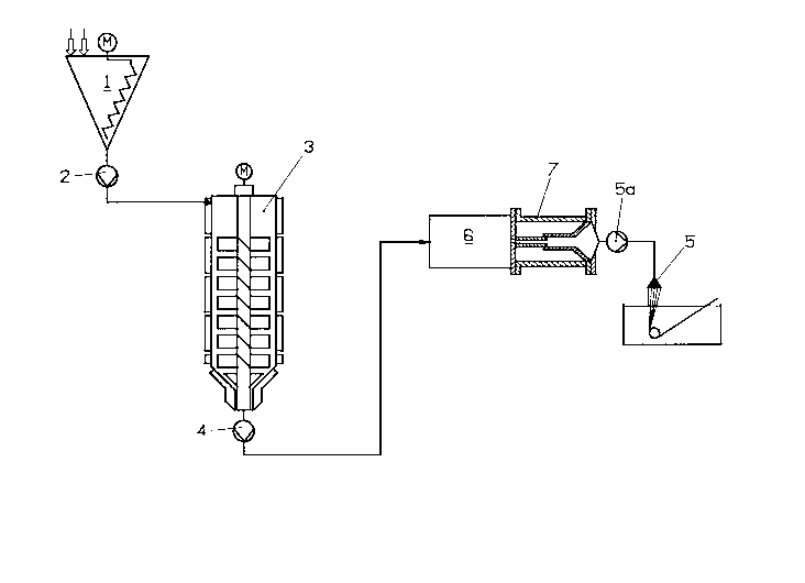
Figre 1 schematically shows the configuration of an
embodiment of the arrangement according to the invention for
the production of a mouldable solution of cellulose in
aqueous NMMO which is spun to fibres. It is pointed out that
for reasons of clarity in the Figure the different components
of the arrangement are not illustrated at the same scale.
In Fig. 1, 1 denotes a mixer, for instance a cone mixer, into
which shredded cellulose and an aqueous NMMO solution are
fed. The feeding thereof is indicated by means of two arrows.
2173~97
-
--12--
In the cone mixer 1, the cellulose and the aqueous NMMO
solution are mixed to form a suspension. The mixing arm of
the cone mixer and the driving element of the mixing arm are
shown by a zigzag line and the letter M respectively. The
suspension obtained contains of from 9 to 13 % by mass of
cellulose, of from 65 and 63 % by mass respectively of NMMO
and water for the rest.
The suspension is removed by means of a pump 2 and fed into a
Filmtruder 3, wherein by means of the thin-film technique
water is withdrawn, while applying reduced pressure and
elevated temperature, until the cellulose dissolves. This
kind of preparation of the cellulose solution is described in
detail in EP-A - 0 356 419 of the applicant, to which we
refer for further information. Thin film treatment apparatus
are known in the art and are made among other producers by
the company Buss AG, Switzerland, under the trade mark
Filmtruder. By means of a pump 4, the ready cellulose
solution is removed from the Filmtruder.
Reference number 6 generally refers to a component of the
arrangement which can be provided optionally and may give
rise to pressure variations. It may be for instance a device
for the feeding of additives, leading to a pressure increase
at the spinning pump 5a due to the volume increase of the
flowing cellulose solution. It may also be a device by means
of which part of the cellulose solution flowing to the
spinneret 5 is diverted in certain intervals for other
purposes. This is the case e.g. with a backwash filter, which
usually is provided upstream to a forming tool, or when
switching between two parallely operated polymer melt filter
cartridges, for instance when one filter unit has to be
removed in order to be cleaned and it is necessary to switch
to the other for maintaining the flow. Backwash filters are
known to those skilled in the art and described for instance
in EP-A - 0 572 369 of the applicant or in EP-A - 0 250 695.
21735~7
-13-
Reference number 7 refers to an embodiment of the device
according to the invention which in the present case is
attached by flange to a component 6 of the arrangement. When
cellulose solution is diverted in component 6 of the
arrangement, this diverted amount of cellulose solution may
be compensated by means of the device 7 according to the
invention, thus avoiding a pressure drop at spinneret 5.
Therefore it is not necessary to interrupt the spinning
process, which may be continued practically under the same
pressure, no discontinuity in spinning occuring.
On the other hand, when for some reason spinneret 5 is
exchanged, the flow of cellulose solution to spinneret 7
naturally having to be stopped, the device according to the
invention is able to take up the amount of cellulose solution
discharged by Filmtruder 3 in the interval of time in which
the flow of cellulose solution is interrupted. Thus it is not
necessary to interrupt the operation of the Filmtruder, no
discontinuity in the quality of the cellulose solution
occurrlng .
In the following, the precise configuration of the device 7
according to the invention and its mode of operation will be
described in detail by means of Figure 2.
Figure 2 shows a section of the device according to the
invention in its simplest embodiment. It consists
substantially of 4 elements: the two blind flanges 8 and 10,
the cylindrical guiding pipe 9 and the piston 11 which is
arranged movably in the guiding pipe. The maximum stroke and
the direction of movement of the piston 11 are indicated by
the letter H and a double arrow respectively. In Figure 2,
the piston 11 is shown in its utmost right position. In the
following, this position will be referred to as minimum
position, since in this case only a m;n;mum amount of
cellulose solution is taken up in the device according to the
invention. When piston 11 is moved to the left by stroke H,
it is located in the maximum position, since in this case a
2173Sg7
-
-14-
maximum of cellulose solution is contained in the device
according to the invention. This maximum position of piston
11 is shown in Figure 2 by a dotted line.
Piston 11 has a receptacle lla located over an inlet pipe 8a
attached to the blind flange 8, which when piston 11 moves
towards the maximum position progressively slides over inlet
pipe 8a like a telescope. Thus, when piston 11 is moving, it
not only is guided by the cylindrical wall 9a of guiding pipe
9, but also by inlet pipe 8a of blind flange 8.
The mode of operation of the device according to the
invention is as follows:
Cellulose solution flows e.g. from the arrangement component
6 shown in Figure 1 through inlet pipe 8a having at its end a
conic enlargement and through receptacle lla and leaves the
device according to the invention through outlet pipe lOa
attached to blind flange 10 and leading directly to the
spinneret (not shown). When in case of exchanging the
spinneret the feeding of cellulose solution from outlet pipe
lOa has to be stopped, the pressure of the cellulose solution
continuing to flow constantly through inlet pipe 8a into the
device according to the invention would increase. This
pressure increase however is compensated by means of the
displacement of piston 11, according to the amount of fed
cellulose solution, towards the left towards the maximum
position. Thus this measure provides space for the cellulose
solution flowing into the device according to the invention
while the spinneret is being changed. When the new spinneret
is operative, outlet pipe lOa is opened again, the movement
of piston 11 simultaneously being stopped, thus being
restarted the spinning operation, since cellulose solution is
again fed continuously from outlet pipe lOa to the spinneret.
The cellulose solution taken up by the device according to
the invention in its guiding pipe 9 during the stopping of
the spinning operation may be fed additionally to the
spinneret by moving towards the minimum position, this step
- 2173~37
-15-
convéniently being carried out over a prolonged period of
time in order not to significantly increase the pressure and
the output amount at the spinneret.
On the other hand, when for some reason the feeding of
cellulose solution to inlet pipe 8a has to be reduced, first
a reserve of cellulose solution is taken up by the device
according to the invention, piston 11 moving to its m~x;mum
position, thus providing space for said reserve of cellulose
solution. When subsequently feeding of cellulose solution to
inlet pipe 8a is reduced, e.g. in order to divert cellulose
solution for other purposes (e.g. for backwashing a filter),
it may be avoided that a pressure drop in the cellulose
solution caused by this measure affects the spinneret by
moving piston 11 at an appropriate rate towards the minimum
position, thereby increasing the transport of cellulose
solution through outlet pipe 10a to the spinneret.
In an operating state wherein it is desired to respond
immediately to positive or negative pressure variations,
piston 11 is located preferably in a position between the
minimum position and the maximum position. In this position,
a sudden pressure drop in inlet pipe 8a may be immediately
compensated by moving piston 11 towards the minimum position.
It is important that the amount of cellulose solution
necessary for the compensation of the pressure drop is not
derived from a clearance volume, as is the case in AT-B - 397
043, but from a space through which cellulose solution flows
constantly, wherein the cellulose solution is constantly
renewed and thus does not age.
A sudden pressure increase in outlet pipe lOa may be
compensated by the immediate movement of the piston towards
the maximum position.
In the following, some construction characteristics of the
device according to the invention will be described in more
detail.
21735~7
-16-
The movement of piston 11 is controlled by means of an inert
gas or by means of an hydraulic oil fed into the pressure
chamber 9c at the gas aperture 9b of guiding pipe 9. When it
is desired to move piston 11 towards the minimum position,
the gas pressure in pressure chamber 9c must be higher than
the pressure prevailing in the cellulose solution. On the
other hand, piston 11 may be moved towards the m~;mum
position by reducing the gas pressure below the pressure of
the cellulose solution. Conveniently, the gas pressure is
controlled continuously. Thus it is also possible to move
piston 11 continuously. The adjustment of the gas pressure
may be carried out in a known way, e.g. by means of a blast
box, and is not shown in Figure 2.
The sealing of pressure chamber 9c against the cellulose
solution in receptacle lla is shown at an enlarged scale by
means of Figure 2a, consisting in a sealing ring 8d fitted
into inlet pipe 8a and a wiping ring.8e which avoids a
contamination of sealing ring 8d. Behind wiping ring 8e, a
guiding ring 8h is fitted into inlet pipe 8a.
The sealing of the cellulose solution against pressure
chamber 9c can also be seen in detail from Figure 2a,
consisting in a sealing ring 8b having a U-shaped section
which avoids the penetration of cellulose solution into
pressure chamber 9c. Directly behind sealing ring 8b, a
guiding ring 8c is located for guiding the receptacle lla at
inlet pipe 8a.
A space 8f between guiding rings 8c and 8h as well as
receptacle lla and inlet pipe 8a is provided for the purpose
of rinsing and lubricating and is fed with lubricant through
lubricating conduit 8g. The lubricant is withdrawn through
conduit 8i (see Fig. 2).
The sealing of the cellulose solution against pressure
chamber 9c at piston 11 is shown at an enlarged scale by
- 2173~97
-17-
means of Figure 2b and is also carried out by means of a
sealing ring llb having a U-shaped section. Behind it a
guiding ring llc is fitted in. The sealing of pressure
chamber 9c against the cellulose solution is not shown in
Fig. 2b and conveniently is arranged analogously to the case
shown in Figure 2a (sealing ring 8d, wiping ring 8e and
guiding ring 8h).
For the sealing of pressure chamber 9c and the cellulose
solution against its surroundings, in blind flanges 8 and 10
O-seals are provided in known manner.
The position of piston 11 within the device according to the
invention may be determined in a known manner, i.e. by means
of a transsonic displacement transducer 8j (Fig. 2a) of the
BALLUF BTL type (made by the company Balluf, Germany), fixed
within blind flange 8. The positioner block 8k is attached to
receptacle lla by means of a ring 81, thus recognizing any
position of receptacle lla between the minimum position and
the maximum position of piston 11. The signal provided by
transsonic displacement transducer 8j may be used as a
control signal in a variety of ways.
Each of the two blind flanges 8 and 10 and guiding pipe 9
have heating jackets 8m, lOb and 9d respectively, by means of
which they may be heated indirectly from the outside.
The rigid connection of blind flanges 8 and 10 to the guiding
pipe 9 is achieved in a known way by means of screws, which
are conducted across bore holes 8n, lOc and 9e respectively.
A preferred embodiment of the device according to the
invention is shown in Figure 3 by means of a section, wherein
components of the device also indicated in Figures 2, 2a and
2b have been designated with identical reference numbers.
The embodiment shown in Figure 3 differs from that shown in
Figure 2 by another (second) guiding pipe 12 provided between
- 2173597
-18-
blind flange 10 and guiding pipe 9 of Figure 2 and by a
static mixer llb welded to the circumference of piston ll and
moving together with piston 11. This static mixer is a pipe
wherein baffles are provided which affect the flow of the
cellulose solution such that it basically does not exhibit a
profile, i.e. that it flows like a plug. Such static mixer
elements are known and are made e.g. by the company Sulzer
Chemtech, Switzerland. In the Figure, the baffles are
indicated by means of two crosses.
In the minimum position of piston 11 shown in Figure 3,
static mixer llb immerses completely into the second guiding
pipe 12, in this position closing evenly with blind flange
10. The sealing of the cellulose solution against pressure
chamber 9c at the front end of the static mixer is in
principle disposed analogously to the sealing at piston 11
shown in Fig. 2b, i.e. by means of a sealing ring having a U-
shaped section to which a guiding ring is joined (both not
shown).
The sealing of pressure chamber 9c against the cellulose
solution is provided at the external circumference of static
mixer llb by means of a sealing ring llc and is shown at an
enlarged scale in Figure 3a. Also in this case, immediately
behind sealing ring llc a wiping ring lld for the protection
of sealing ring llc against contamination is provided. Static
mixer llb is conducted in the second guiding pipe 12 by means
of guiding ring lle provided behind it. Space llf is provided
for lubrication purposes, the feeding and withdrawal of
lubricant being carried out through apertures 12b and 12 c
respectively.
The static mixer may be heated indirectly from the outside by
means of heating jacket 12a.
It has been shown that the incorporation of a static mixer in
the device according to the invention is particularly
advantageous when processing the thermally unstable cellulose
-- 2173597
-19-
solutions in order to obtain a good plug flow and reduced
residence time. Besides, it is also advantageous to use
static mixers wherein the interior parts may be fed with
heating medium/cooling medium, thus being possible to
additionally heat/cool the flowing cellulose solution.