Language selection

Search

Patent 2173771 Summary

Third-party information liability

Some of the information on this Web page has been provided by external sources. The Government of Canada is not responsible for the accuracy, reliability or currency of the information supplied by external sources. Users wishing to rely upon this information should consult directly with the source of the information. Content provided by external sources is not subject to official languages, privacy and accessibility requirements.

Claims and Abstract availability

Any discrepancies in the text and image of the Claims and Abstract are due to differing posting times. Text of the Claims and Abstract are posted:

  • At the time the application is open to public inspection;
  • At the time of issue of the patent (grant).
(12) Patent: (11) CA 2173771
(54) English Title: METHOD FOR BUTT-COUPLING OPTICAL FIBRE CONNECTORS COMPRISING A CYLINDRICAL FERRULE
(54) French Title: METHODE SERVANT A RACCORDER BOUT A BOUT DES CONNECTEURS DE FIBRES OPTIQUES, FAISANT APPEL A DES BAGUES CYLINDRIQUES
Status: Expired and beyond the Period of Reversal
Bibliographic Data
(51) International Patent Classification (IPC):
  • G02B 6/255 (2006.01)
  • G02B 6/25 (2006.01)
  • G02B 6/38 (2006.01)
(72) Inventors :
  • PITASSI, STEFANO (Italy)
(73) Owners :
  • SIRTI S.P.A.
(71) Applicants :
  • SIRTI S.P.A. (Italy)
(74) Agent: MARKS & CLERK
(74) Associate agent:
(45) Issued: 1998-08-11
(22) Filed Date: 1996-04-10
(41) Open to Public Inspection: 1996-11-10
Examination requested: 1996-09-26
Availability of licence: N/A
Dedicated to the Public: N/A
(25) Language of filing: English

Patent Cooperation Treaty (PCT): No

(30) Application Priority Data:
Application No. Country/Territory Date
MI95 A 000921 (Italy) 1995-05-09

Abstracts

English Abstract


The method for butt-coupling an optical fibre connector comprising
a cylindrical ferrule consists of the following steps:
a) preparing the head of the optical fibre for insertion into
the ferrule;
b) applying a thin layer of resin to the fibre, taking care not
to soil the cut end of the fibre with said resin;
c) inserting said fibre into the sized hole of the cylindrical
ferrule;
d) by means of an alignment bush, coupling said ferrule to a
reference ferrule in which a piece of fibre has been previously
housed and fixed such that the end surface of said fibre lies
inward of the end surface of the reference ferrule;
e) crosslinking the resin.


French Abstract

Méthode de couplage par raccordement en about d'un connecteur de fibre optique à ferrule cylindrique. Les étapes à suivre sont les suivantes : a) préparer la tête de la fibre optique pour l'insérer dans la ferrule; b) enduire la fibre d'une mince couche de résine en ménageant l'extrémité coupée de la fibre; c) insérer la fibre dans l'orifice dimensionné de la ferrule cylindrique; d) au moyen d'un manchon d'alignement, coupler la ferrule à une ferrule de référence dans laquelle une partie de la fibre a été logée et fixée de sorte que la partie terminale de la fibre soit à l'intérieur de la partie terminale de la ferrule de référence; e) réticuler la résine.

Claims

Note: Claims are shown in the official language in which they were submitted.

- 6 -
CLAIMS
1. A method for butt-coupling optical fibre connectors
comprising a cylindrical ferrule, consisting of the following
steps:
a) preparing the head of the optical fibre and cutting its end
for insertion into the hole in the cylindrical ferrule;
b) applying a thin layer of resin to the fibre, taking care not
to soil the cut end of the fibre with said resin;
c) inserting said fibre into the sized hole of the cylindrical
ferrule, the end surface of which has been previously lapped in a
convex manner;
d) by means of an alignment bush, coupling said ferrule to a
reference ferrule the end surface of which is convex, and in which
a piece of fibre has been previously housed and fixed such that
the end surface of said fibre lies inward of the end surface of
the reference ferrule;
e) crosslinking the resin by heating.
2. A method as claimed in claim 1, characterised in that said
crosslinking takes place at ambient temperature.
3. A method as claimed in claim 1 or 2, characterised in that
following the operation under point e), the fibre inserted into
the ferrule is further polished at its end.
4. A method as claimed in claim 1 or 2, characterised in that
the cut surface of the fibre inserted into the ferrule is
perpendicular to the longitudinal axis of the fibre.
5. A method as claimed in any one of the preceding claims,
characterised in that the ferrule is assembled together with all
the constituent parts of the connector.

Description

Note: Descriptions are shown in the official language in which they were submitted.


- 2173771
.
- 1 -
METHOD FOR BUTT-COUPLIN~ OPTICAL FIBRE CONN~CTORS COMPRISING A
CY~INDRICA~ FERRULE
This invention relates to a new method for butt-coupling optica~
fibre connectors comprising a cylindrical ferrule.
In preparing a connector comprising a cylindrical ferrule, a vital
operation for its reliability and adequate optical performance
~insertion and return losses) is the polishing of the end surface
of the ferrule and in particular of the fibre glued into it.
Typically, in the current state of the art, the following briefly
described procedure is used.
The previously prepared optical fibre is inserted into the
cylindrical ferrule so that a certain length of it projects beyond
the ferrule surface. Resin is applied about the projecting
1~ portion of optical fibre to ensure that the fibre is also
perfectly secured to the ferrule at its end. It is essential to
ensure that part of the resin infiltrates between the fibre and
the sized hole in the cylindrical ferrule.
To ensure proper operation of the connector the projecting fibre
portion is then cut off as far as the base of the resin. The
entire end surface of the ferrule, the fibre and the overlying
portion of resin are subjected to lapping to obtain a convex

2173771
surface free from roughness. To further increase the quality of
the connector the said surface, and in particular of the fibre,
must be finely polished.
The lapping and polishing are effected by an abrasive process
using suitable fine grain papers ~from a few microns to fractions
of a micron) and colloidal solutions. Overall, the procedure is
onerous in terms of time and resources employed because the
simultaneous presence of three different types of material ~fibre,
resin and the material of the cylindrical ferrule) means that
1G these tend to be abraded differently such that if the entire
process is not controlled, a damaging shrinkage of the end surface
of the fibre relative to that of the cylindrical ferrule occurs.
An object of the present invention is to define a method for butt-
coupling connectors comprising a cylindrical ferrule which
eliminates or at least reduces said drawbacks of the known art.
A further object of the present invention is to achieve a method
which is simpler, cheaper, involves less time and provides a
superior optical performance, in particular in terms of return
losses.
The present invention provides a method for butt-coupling an
optical fibre connector comprising a cylindrical ferrule,
consisting of the following steps:
a) preparing the head of the optical fibre by removing its
cladding and then cutting the end to be inserted into the hole in
the cylindrical ferrule;
b) applying a thin layer of resin to the fibre, taking care not
to soil the cut end of the fibre with said resin;

- 2173771
c) inserting said fibre into the sized hole of the cylindrical
ferrule, the end surface of which has been previously lapped in a
convex manner;
d) by means of an alignment bush, coupling said ferrule to a
reference ferrule the end surface of which is convex, and in which
a piece of fibre has been previously housed and fixed such that
the end surface of said fibre lies inward of the end surface of
the reference ferrule;
e) crosslinking the resin by heating.
In alternative embodiments of the present invention, said
crosslinking may take place at ambient temperature if the type of
resin allows it.
The end surface of the fibre inserted into the hole in the ferrule
may then be further polished if it is desired to make this surface
convex as that of the ferrule, by using an abrasive paper of very
fine grain ~less than one micron). In view of the characteristics
of the proposed method, said polishing is not critical for the
connector and can even be done manually.
Alternatively, or after this latter polishing operation, the
ferrule can be assembled with all the constituent parts of the
connector.
Further characteristics and details of the method of the present
invention will be more apparent from the description given
hereinafter by way of non-limiting example with reference to the
accompanying drawings, in which:
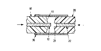
Figure 1 shows the insertion of the optical fibre into the sized
hole of the cylindrical ferrule to be butt-coupled;

- 2173771
-- 4 --
Figure 2 shows the connection between the ferrule to be butt-
coupled and the reference ferrule, by means of an alignment bush;
Figure 3 is a section through the end part of a reference ferrule.
In Figure 1 the reference numeral 10 indicates a ferrule to be
butt-coupled. It has a convex end surface 11, with the cut fibre
12 inserted to the extent of projecting from said ferrule 10.
Figure 2 shows the connection between the ferrule 10 to be butt-
coupled and a reference ferrule 20, the structure of which is more
evident from Figure 3. In the reference ferrule 20, which also
has a convex end surface 21, the optical fibre portion 22 lies
inwards of the end surface 21. In the coupling arrangement shown
in Figure 2, this withdrawal of the optical fibre 2~ from the
surface 21 determines the corresponding projection of the optical
fibre portion 12 from the ferrule 10 to be butt-coupled.
It is hence apparent that the aforedescribed method is applicable
to all optical fibre connectors using cylindrical ferrules with a
sized hole, whatever the constituent material of the ferrule or
the type of resin used for gluing the fibre. The only conditions
which have necessarily to be respected are the following:
1. After the fibre has been positioned in the ferrule hole, it
must be ensured that the resin is perfectly crosslinked
~hardened).
2. It must be ensured that the fibre portion in the vicinity of
the end surface of the ferrule has not been glued to the ferrule
hole.
To avoid the step involving the further polishing of the fibre end
surface, the fibre must be cut, under point a~, perpendicular to

- 2173771
-- 5 --
its longitudinal axis.
Finally it is essential that in the reference ferrule the fibre
lies inward of ~withdrawn from) the end surface of the ferrule, so
that during the coupling to the other ferrule the butt-coupled
fibre is able to protrude.

Representative Drawing
A single figure which represents the drawing illustrating the invention.
Administrative Status

2024-08-01:As part of the Next Generation Patents (NGP) transition, the Canadian Patents Database (CPD) now contains a more detailed Event History, which replicates the Event Log of our new back-office solution.

Please note that "Inactive:" events refers to events no longer in use in our new back-office solution.

For a clearer understanding of the status of the application/patent presented on this page, the site Disclaimer , as well as the definitions for Patent , Event History , Maintenance Fee  and Payment History  should be consulted.

Event History

Description Date
Inactive: IPC from MCD 2006-03-12
Time Limit for Reversal Expired 2000-04-10
Letter Sent 1999-04-12
Grant by Issuance 1998-08-11
Inactive: Final fee received 1998-04-01
Pre-grant 1998-04-01
Notice of Allowance is Issued 1997-12-12
Letter Sent 1997-12-12
Inactive: Status info is complete as of Log entry date 1997-12-04
Inactive: Application prosecuted on TS as of Log entry date 1997-12-04
Inactive: Approved for allowance (AFA) 1997-11-21
Application Published (Open to Public Inspection) 1996-11-10
All Requirements for Examination Determined Compliant 1996-09-26
Request for Examination Requirements Determined Compliant 1996-09-26

Abandonment History

There is no abandonment history.

Maintenance Fee

The last payment was received on 1998-03-31

Note : If the full payment has not been received on or before the date indicated, a further fee may be required which may be one of the following

  • the reinstatement fee;
  • the late payment fee; or
  • additional fee to reverse deemed expiry.

Please refer to the CIPO Patent Fees web page to see all current fee amounts.

Fee History

Fee Type Anniversary Year Due Date Paid Date
Request for examination - standard 1996-09-26
MF (application, 2nd anniv.) - standard 02 1998-04-14 1998-03-31
Final fee - standard 1998-04-01
Owners on Record

Note: Records showing the ownership history in alphabetical order.

Current Owners on Record
SIRTI S.P.A.
Past Owners on Record
STEFANO PITASSI
Past Owners that do not appear in the "Owners on Record" listing will appear in other documentation within the application.
Documents

To view selected files, please enter reCAPTCHA code :


To view images, click a link in the Document Description column. To download the documents, select one or more checkboxes in the first column and then click the "Download Selected in PDF format (Zip Archive)" or the "Download Selected as Single PDF" button.

List of published and non-published patent-specific documents on the CPD .

If you have any difficulty accessing content, you can call the Client Service Centre at 1-866-997-1936 or send them an e-mail at CIPO Client Service Centre.


Document
Description 
Date
(yyyy-mm-dd) 
Number of pages   Size of Image (KB) 
Cover Page 1998-08-03 1 44
Representative drawing 1998-08-03 1 5
Abstract 1996-07-19 1 16
Description 1996-07-19 5 136
Cover Page 1996-07-19 1 16
Claims 1996-07-19 1 32
Drawings 1996-07-19 1 21
Representative drawing 1997-11-24 1 7
Commissioner's Notice - Application Found Allowable 1997-12-12 1 165
Reminder of maintenance fee due 1997-12-11 1 111
Maintenance Fee Notice 1999-05-10 1 179
Correspondence 1998-04-01 1 46
Courtesy - Office Letter 1996-11-18 1 51
Prosecution correspondence 1996-09-26 1 33
Prosecution correspondence 1997-05-07 1 32
Prosecution correspondence 1997-05-07 3 147
Prosecution correspondence 1996-04-10 4 214