Language selection

Search

Patent 2173914 Summary

Third-party information liability

Some of the information on this Web page has been provided by external sources. The Government of Canada is not responsible for the accuracy, reliability or currency of the information supplied by external sources. Users wishing to rely upon this information should consult directly with the source of the information. Content provided by external sources is not subject to official languages, privacy and accessibility requirements.

Claims and Abstract availability

Any discrepancies in the text and image of the Claims and Abstract are due to differing posting times. Text of the Claims and Abstract are posted:

  • At the time the application is open to public inspection;
  • At the time of issue of the patent (grant).
(12) Patent: (11) CA 2173914
(54) English Title: INTERVENTIONAL CATHETER
(54) French Title: CATHETER POUR INTERVENTIONS
Status: Expired and beyond the Period of Reversal
Bibliographic Data
(51) International Patent Classification (IPC):
  • A61M 25/10 (2013.01)
  • A61M 29/02 (2006.01)
(72) Inventors :
  • HELLER, MATHIAS (Switzerland)
  • FEHSE, JAN (Switzerland)
(73) Owners :
  • SCHNEIDER (EUROPE) GMBH
(71) Applicants :
  • SCHNEIDER (EUROPE) GMBH (Switzerland)
(74) Agent: SMART & BIGGAR LP
(74) Associate agent:
(45) Issued: 1999-02-16
(22) Filed Date: 1996-04-11
(41) Open to Public Inspection: 1996-11-06
Examination requested: 1996-04-11
Availability of licence: N/A
Dedicated to the Public: N/A
(25) Language of filing: English

Patent Cooperation Treaty (PCT): No

(30) Application Priority Data:
Application No. Country/Territory Date
95106808.9 (European Patent Office (EPO)) 1995-05-05

Abstracts

English Abstract


An interventional catheter for angioplasty and the like,
comprising a catheter tube (1) formed of two superposed
layers 3 and 4 of materials different from one another.
Over the distal end 2 of the catheter tube 1 is
positioned a balloon 6 with a distal neck 7 sealingly
surrounding the outer layer 4 of the catheter tube. A
tip 8 is formed by a piece of material 12 welded to the
distal end 2 of the catheter tube and the distal neck 7
of the balloon 6 also welds to the proximal portion 9 of
the tip 8.


French Abstract

Cathéter d'intervention servant, notamment, pour les angioplasties. Il comprend un tube (1) formé de deux couches superposées (3 et 4) de matières différentes. A l'extrémité distale (2) du tube de cathéter (1) est placé un ballonnet (6) ayant un col distal (7) entourant de façon étanche la couche extérieure (4) du tube de cathéter. Une pointe (8) est formée d'une pièce de matière (12) soudée à l'extrémité distale (2) du tube de cathéter, et le col distal (7) du ballonnet (6) est également soudé à la partie proximale (9) de la pointe (8).

Claims

Note: Claims are shown in the official language in which they were submitted.

THE EMBODIMENTS OF THE INVENTION IN WHICH AN EXCLUSIVE
PROPERTY OR PRIVILEGE IS CLAIMED ARE DEFINED AS FOLLOWS:
1. An interventional catheter comprising a catheter tube
having proximal and distal ends, an inner layer of material
forming a longitudinal lumen in the catheter tube for the
sliding fit of a guide wire, an outer layer of material
superposed to said inner layer and forming an outer surface of the
catheter tube, said inner and outer layers of material being
secured in relation to one another and having mechanical
properties differing from one another, a balloon with proximal
and distal necks whereby the distal neck of the balloon
sealingly surrounds the catheter tube, and a tip at the distal end
of the catheter tube, wherein said tip is a separate piece of
material having proximal and distal portions with said proximal
portion being arranged as a longitudinal extension of said outer
layer, said inner layer ending proximally of said proximal
portion of the separate piece of material, and said separate
piece of material having an inner wall in longitudinal alignment
with said longitudinal lumen.
2. An interventional catheter according to claim 1,
wherein said separate piece of material tapers distally.
3. An interventional catheter according to claim 1 or 2,
wherein said separate piece of material is welded to the distal
end of the catheter tube.
4. An interventional catheter according to any one of
claims 1 to 3, wherein the distal neck of the balloon sealingly

surrounds a part of the proximal portion of the separate piece
of material.
5. An interventional catheter according to claim 4,
wherein the distal neck of the balloon is welded to the
proximal portion of the separate piece of material.
6. An interventional catheter according to any one of
claims 1 to 5, wherein said separate piece of material is made
of a polyamid.

Description

Note: Descriptions are shown in the official language in which they were submitted.


21 7391 4
This invention relates to an interventional catheter
comprising a catheter tube having proximal and distal
ends, an inner layer of material forming a longitudinal
lumen in the catheter tube for the sliding fit of a
guide wire, an outer layer of material superposed to
said inner layer and forming an outer surface of the
catheter tube, said inner and outer layers of materials
being secured in relation to one another and having
mechanical properties differing from one another, a
balloon with proximal and distal necks whereby the
distal neck of the balloon sealingly surrounds the
catheter tube, and a tip at the distal end of the
catheter tube.
Over the wire catheters are now widely used for
interventions such as percutaneous transluminal
angioplasty. A problem with these catheters is that the
guide wire may clog into the longitudinal lumen of the
catheter; as a result, the guide wire may follow the
balloon upon withdrawal thereof after the inflation
procedure, thereby making it necessary to re-insert the
guide wire into the treated area of the blood vessel for
re-positioning a balloon in case a second inflation is
needed. The catheter also has to achieve an acceptable
compromise between the requirements of some stiffness to
assure good pushability and of some flexibility to
assure kink resistance. And of course it has to permit
safe attachment of the balloon to the catheter tube.
European Patent Application N~ 93117403.1 filed October
27, 1993 by the Applicant shows a catheter comprising a
catheter tube having two superposed layers of materials
secured in relation to one another and with mechanical
properties differing from one another, a longitudinal
lumen in the catheter tube for the sliding fit of a
guide wire, and a balloon with a proximal end and a

2~73914
distal end sealingly surrounding the catheter tube,
whereby the catheter tube has an inner layer forming the
longitudinal lumen and an outer layer forming the outer
surface of the catheter tube. In this catheter, the
inner layer is formed of a material with lower friction
coefficient than the material forming the outer layer,
whereby there is no more risk of having the guide wire
clogging in the longitudinal lumen of the catheter tube.
The document WO 92/11893 describes an intra aortic
balloon apparatus comprising a hollow catheter in which
is located an elongated member forming a central lumen
extending out of the catheter at the distal end thereof.
An aortic pumping balloon is positioned over the
elongated member and the distal end of the balloon is
bonded to a tip engaged over the distal end of the
elongated member. In order to achieve a balance of
flexibility and remains and to avoid kinking, the
elongated member is formed of an inner layer comprised
of a soft elastomeric material and the outer layer is
comprised of a hard plastic material. This balloon
apparatus cannot be loaded with a guide wire and moved
into tortuous vessels with the guide wire loaded inside
the elongated tube. Furthermore, this balloon apparatus
cannot be introduced into narrow vessels or stenoses nor
can it be passed through narrow punctures to enter the
blood vessels because of the large profile of the folded
balloon resulting from the fact that the balloon is
bonded to an intermediate tip which in turn is mounted
over and bonded to the elongated element.
The purpose of this invention is to present an
interventional, low profile, highly resistant balloon
catheter with improved moveability into tortuous vessels
and an added capacity of reducing the risk of injury.

CA 02173914 1998-11-02
.
To this effect, the invention provides an inter-
ventional catheter comprising a catheter tube having proximal
and distal ends, an inner layer of material forming a
longitudinal lumen in the catheter tube for the sliding fit
of a guide wire, an outer layer of material superposed to
said inner layer and forming an outer surface of the catheter
tube, said inner and outer layers of material being secured
in relation to one another and having mechanical properties
differing from one another, a balloon with proximal and distal
necks whereby the distal neck of the balloon sealingly surrounds
the catheter tube, and a tip at the distal end of the catheter
tube, wherein said tip is a separate piece of material having
proximal and distal portions with said proximal portion being
arranged as a longitudinal extension of said outer layer, said
inner layer ending proximally of said proximal portion of the
separate piece of material, and said separate piece of material
having an inner wall in longitudinal alignment with said
longitudinal lumen.
Accordingly, where the tip is a separate piece of
material having proximal and distal portions whereby said
proximal portion is in longitudinal extension of the outer
layer, with the inner layer ending proximally of the said
proximal portion and the separate piece of material having an
inner wall in longitudinal alignment with the longitudinal
lumen, the tip allows a low profile with selective flexibility
at the distal end of the catheter tube; this results in a
better trackability through narrow or tortuous vessels, as
well as in a strong reduction of the risk of injury. There is
75490-17

CA 02173914 1998-11-02
also a superior protection of the distal extremity of the
superposed layers of materials against any risk of delamination.
The catheter thus conforms easily with the vessel configurations,
more particularly along low radius curves, and the resulting low
friction substantially reduces the risk of injury to the vessel
in these delicate areas.
Where the separate piece of material forming the tip
tapers distally, the catheter end may have a strong diameter
reduction which cannot be achieved by a simple multilayer
catheter end because of the hazardous loss of resistance of the
superposed layers. In addition, the distal end of the catheter
has an added stepped flexibility which enhances the catheter
capacity to reach very narrow or tortuous vessel locations with
still less risk of injury.
When the separate piece of material forming the tip
is welded to the distal end of the catheter tube, a simple and
rapid manufacture may be achieved in which the distal neck of
the balloon, the superposed layers of materials and tip are all
weld assembled in one single step.
For a smooth transition and added safety, the distal
neck of the balloon may sealingly surround a part of the
proximal portion of the separate piece of material, sealing
being for instance by welding.
These and other objects, features and advantages of
the invention will become readily apparent from the following
de*ailed description with reference to the accompanying
drawings which show, diagrammatically and by way of example
75490-17

CA 02173914 1998-11-02
only, preferred but still illustrative embodiments of the
invention.
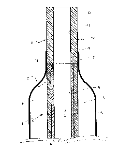
Figure 1 is a longitudinal cut out of a first
embodiment.
Figure 2 is a longitudinal cut out of a second
embodiment.
The interventional catheter shown in Figure 1
comprises a catheter tube 1 having a proximal end (not shown)
and a distal end 2. The catheter tube 1 is formed of two
superposed continuous layers 3 and 4 extending all over the
length of tube l; this tubing, which may be achieved by the
known coextrusion technology, i. e. by extruding the outer
layer 4 over the inner layer, is comprised of a polyethylene,
preferably a high density polyethylene, for the inner layer 3,
and of a polyamid for the outer layer 4. The inner layer
thus forms a longitudinal lumen 5 with a very low friction
coefficient, lower than that of the material forming the outer
layer 4, and a non-kinking capacity. The outer layer 4, which
forms an outer surface of the catheter tube, is easily weldable
to the materials commonly used for making balloons for angio-
plasty purposes and the like. The lumen 5 is for the sliding
fit of a guide wire (not shown).
Over the distal end 2 of the catheter tube 1 is
positioned a balloon 6 with a distal neck 7 which is sealed
to the outer layer 4 of the catheter tube 1, for instance by
welding. The balloon 6 has a proximal neck (not shown) which
is affixed to the catheter tube 1 which is also provided with
75490-17

CA 02173914 1998-11-02
an inflation lumen for the balloon 6 in a conventional manner.
Preferably, the balloon 6 is made of a polyamid.
A tip 8 formed by a piece of material 12 having a
proximal portion 9 and a distal portion 10 is arranged at the
distal end 2 of the catheter tube 1. This tip has its proximal
portion 9 in longitudinal extension of the outer layer 4 of the
catheter tube 1, and the inner layer 3 of the catheter tube 1
ends proximally of the proximal portion 9 of tip 8. The tip 8
has an inner wall 11 in longitudinal alignment with the
longitudinal lumen 5 and therefore the proximal extremity of
its proximal end fully protects the distal ends of inner and
outer layers 3 and 4. The proximal end of the proximal portion
9 of tip 8 is welded to the distal end 2 of the catheter tube 1,
and the distal neck 7 of the balloon 6 sealingly surrounds, for
instance by welding, a part of the proximal portion 9 of tip 8.
The tip 8 is preferably made of a polyamid, and
welding of the distal neck 7 of the balloon 6 to the distal end
2 of the catheter tube 1 and to the proximal portion 9 of the
tip 8 may be achieved in one single step. Welding may be
effected by laser or hot air.
The interventional catheter shown in Figure 2
comprises the same integers and arrangements as the catheter
shown in Figure 1, which are identically referenced. In
addition, the piece of material 12 forming the tip 8 tapers
distally as shown by reference numeral 14. As shown, the
diameter reduction extends slightly above the diameter of the
inner layer 3, a reduction which could not be achieved on the
75490-17

CA 02173914 1998-11-02
two layer catheter tube 1 without a serious risk of damage to
the outer layer 4. It may be noted that, due to the one
integral configuration of the piece of material 12 forming the
tip 8, an even greater diameter reduction could be achieved,
substantially beneath the diameter of the outer layer, as shown
in phantom at 14.
75490-17

Representative Drawing
A single figure which represents the drawing illustrating the invention.
Administrative Status

2024-08-01:As part of the Next Generation Patents (NGP) transition, the Canadian Patents Database (CPD) now contains a more detailed Event History, which replicates the Event Log of our new back-office solution.

Please note that "Inactive:" events refers to events no longer in use in our new back-office solution.

For a clearer understanding of the status of the application/patent presented on this page, the site Disclaimer , as well as the definitions for Patent , Event History , Maintenance Fee  and Payment History  should be consulted.

Event History

Description Date
Inactive: IPC deactivated 2015-08-29
Inactive: IPC assigned 2015-04-29
Inactive: First IPC assigned 2015-04-29
Inactive: IPC removed 2015-04-29
Inactive: IPC assigned 2015-04-29
Inactive: IPC expired 2013-01-01
Inactive: IPC from MCD 2006-03-12
Time Limit for Reversal Expired 2002-04-11
Letter Sent 2001-04-11
Grant by Issuance 1999-02-16
Letter Sent 1998-11-30
Amendment After Allowance Requirements Determined Compliant 1998-11-30
Amendment After Allowance (AAA) Received 1998-11-16
Pre-grant 1998-11-02
Inactive: Final fee received 1998-11-02
Amendment After Allowance (AAA) Received 1998-11-02
Inactive: Amendment after Allowance Fee Processed 1998-11-02
Letter Sent 1998-08-27
Notice of Allowance is Issued 1998-08-27
Inactive: Approved for allowance (AFA) 1998-08-07
Inactive: Application prosecuted on TS as of Log entry date 1998-04-23
Inactive: Status info is complete as of Log entry date 1998-04-23
Inactive: Multiple transfers 1998-03-11
Application Published (Open to Public Inspection) 1996-11-06
Request for Examination Requirements Determined Compliant 1996-04-11
All Requirements for Examination Determined Compliant 1996-04-11

Abandonment History

There is no abandonment history.

Maintenance Fee

The last payment was received on 1998-03-04

Note : If the full payment has not been received on or before the date indicated, a further fee may be required which may be one of the following

  • the reinstatement fee;
  • the late payment fee; or
  • additional fee to reverse deemed expiry.

Please refer to the CIPO Patent Fees web page to see all current fee amounts.

Fee History

Fee Type Anniversary Year Due Date Paid Date
Request for examination - standard 1996-04-11
MF (application, 2nd anniv.) - standard 02 1998-04-14 1998-03-04
Registration of a document 1998-03-11
Final fee - standard 1998-11-02
1998-11-02
MF (patent, 3rd anniv.) - standard 1999-04-12 1999-02-19
MF (patent, 4th anniv.) - standard 2000-04-11 2000-04-05
Owners on Record

Note: Records showing the ownership history in alphabetical order.

Current Owners on Record
SCHNEIDER (EUROPE) GMBH
Past Owners on Record
JAN FEHSE
MATHIAS HELLER
Past Owners that do not appear in the "Owners on Record" listing will appear in other documentation within the application.
Documents

To view selected files, please enter reCAPTCHA code :


To view images, click a link in the Document Description column. To download the documents, select one or more checkboxes in the first column and then click the "Download Selected in PDF format (Zip Archive)" or the "Download Selected as Single PDF" button.

List of published and non-published patent-specific documents on the CPD .

If you have any difficulty accessing content, you can call the Client Service Centre at 1-866-997-1936 or send them an e-mail at CIPO Client Service Centre.


Document
Description 
Date
(yyyy-mm-dd) 
Number of pages   Size of Image (KB) 
Cover Page 1999-02-09 1 42
Description 1998-11-02 7 262
Claims 1998-11-02 2 52
Drawings 1998-11-02 2 50
Representative drawing 1998-02-05 1 23
Representative drawing 1999-02-09 1 11
Cover Page 1996-07-16 1 16
Abstract 1996-07-16 1 15
Claims 1996-07-16 2 59
Description 1996-07-16 8 338
Drawings 1996-07-16 4 94
Reminder of maintenance fee due 1997-12-15 1 111
Commissioner's Notice - Application Found Allowable 1998-08-27 1 166
Maintenance Fee Notice 2001-05-09 1 178
Fees 2000-04-05 1 39
Correspondence 1998-11-02 2 67