Note: Descriptions are shown in the official language in which they were submitted.
wo96/04856 ~ ~ 7 ~ CT/US95108987
SURGICAL APPARATUS ~IAVING A UNIVERSAL
HANDLE FOR ACTUATING VAR~OUS ATTAC~IMENTS
The present invention relates generally to surgical instmm~nts, and
more particularly, to an instnument for use in laparoscopic surgical procedures, in
which the instrument in~ des a universal handle that can actuate various di~er~nl
types of ~tt~..hment~
10 BACKGROUI~D OF THE INVENTION
In laparoscopic procedures, surgery is performed in the abdomen
through a small incision in the skin. Such procedures typically involve distending
the abdominal cavity away from the underlying organs to improve access and
l5 visibility, using gas in~m~tion or a mechanical distension technique. Laparoscopic
procedures generally require the surgeon to act on organs, tissues and vessels at a
distance from the incision, thereby requiring that any instruments used in such
procedures be long and narrow while being functionally controllable from the
plo~illlal end of the instrument.
Many dirrerel.l procedures may be performed during laparoscopic
surgery requiring the use of many di~ie11l instn-m~nt.c, such as, ligating clip
appliers, staplers, disposable scissors and tackers. P.ese"Lly, however, no universal
handle is available to operate all of these varied instruments. Thus, hospital
25. inventory is increased, instrument costs to hospitals are increased, the number of
handles which require cleaning is increased, and the number of instruments present
on the surgical tool table is increased. Additionally, the surgeon must become
familiar with the operation of each of the different instnuments, some of which have
a plurality of triggers for ~ct~l~ting the di~erenl operating mech~ni~m~ of that30 instrument.
WO 96/048S6 PCT/US95/08987
For example, in laparoscopic surgical procedures, it is frequently
necessary to ligate ducts, such as blood vessels, or other severed tissues. For this
purpose, it is well-known to use surgical clip appliers that advance a clip and clamp
S a clip, such as that described in U.S. Patent No. 5,084,057. However, such a clip
applier discloses the use of two actu~ting triggers, one to advance the clip and the
other to clamp the clip. The dual trigger clip applier does not provide the ease of
use and simplicity that acco.,.panies the use of a single trigger instrument. Inaddition, the costs of m~nllf~cturing such a clip applier are increased since a handle
with two triggers requires the additional molding and m~nuf~cture of a second
trigger, associated trigger parts and additional lockouts.
Known laparoscopic instruments for applying surgical clips and
which have a single ~ctu~ting trigger include those devices disclosed in U.S. Patent
Nos. 5,289,963; 5,192,288; 5,171,249; and 5,171,247. The clip applier of U.S.
Patent No. S,289,963, however, only has a movable clip advance mech~ni~m not a
movable clamping mech~ni~m Therefore only one actu~ting trigger is necess~ry.
The clip appliers of U.S. Patent Nos. 5,192,288; 5,171,249; and 5,171,247 disclose
devices having both movable clip advance and movable clamping meçh~ni~m~. The
two meçh~nicm~, however, do not operate independently, but rather are operated
~imlllt~neously as the trigger is actuated. Also, in each of these three patents, a clip
is automatically advanced upon release of the trigger after the previous clip has
been clamped. Therefore, the operator has less control of the clip feed and there is
a chance that the clip may ~cci~ent~lly shoot out of the device or get caught orsnagged by frictional forces so that the clip cannot advance.
In the case of a clip applier, it is also desirable that only one clip be
fed into the jaws of the device at a time. For example, in previously known
instruments, a ratchet and pawl mech~nism was used to prevent the trigger from
returning to the clip reload position until the previously loaded clip had been
clamped to a duct. In one instrument, described in U.S. Patent No. 5,289,963, the
Wo 96104856 PCTIUS95J08987
ratchet and pawl mech~ni~m is mounted to a longitu~in~lly movable plunger that
~chlates the operating mech~ni~m.c. In this case, however, the ratchet and pawl
mrrh~ni~m has the disadvantage of preventing the surgeon from reclosing the jawsof the device should the surgeon desire to confirm that the clip has been properly
clamped. In another instrument, described in U.S. Patent No. 5,192,288, the
ratcheting mech~ni~m inr.hlrlçs a hooked end of the pawl that Pn~ges a grooved
path of ridges and cliffs on the trigger. However, this r~tçheting mech~ni~m has a
complex construction, and it may be unreliable since one must rely on the resiliency
of the pawl to engage the grooved path.
It is also desirable in some instances to have a "resposable"
instrument, i.e., an instrument having a disposable end effector detachable from a
reusable handle. Most laparoscopic instruments are either fully disposable or fi~lly
reusable. Single use disposable instruments, however, are often not cost effective,
whereas reusable instruments require thorough cleaning and sterilization betweenuses. U.S. Patent No. 5,040,715 discloses the use of a detaçh~ble end effector
having a finger structure for enSJ~ging an internal portion of the handle and having a
movable sleeve for (li~Pn~ging the end effector from the handle. However, the
finger structure and sleeve make the end effector relatively expensive since
additional molding and m~nuf~ctllring are required. Also, tight tolerances are
required to insure a secure fit between the ~ttachment and the handle. Being
disposable, the end effector should be as simple and inexpensive as possible.
Other known laparoscopic instruments have att~çhmrnt devices for
connecting and disconnecting various end effectors. However, these ~tt~çhm~nt
devices are typically quick connect ~ttaçhments that require that a knob be
depressed as an end effector is ~tt~çhed. Another commonly known att~çhmrnt
means used with laparoscopic instruments is the bayonet mount. However, the
bayonet mount requires an additional rotational motion, and if the rotational motion
is not performed, the end effector cannot be securely ~tt~r.hed These ~tt~çhmrnt
WO 96/048~;6 ~ ~ 7 ~ PCT/US95/08987
devices thus require additional manipulation, such as a coordinated, two-handed
movement, to attach the end effector to the handle.
From the discussion above, it should be apparent that there is a need
5 for a surgical appar~ s that can be used in laparoscopic procedures and that
inr.llldes a universal actu~ting handle for use with a variety of att~chments or end
effectors and that can convert a single lever motion of the handle into two separate
and independent actuator motions. In addition, there is a need for a surgical
apparatus that includes a ratchet and pawl meçh~ni~m for preventing the return of
10 the actll~ting trigger so that only one clip is fed at a time, but that permits reclosure
of the trigger to insure that the function of the end effector is properly performed.
In addition, there is a need for a surgical apparatus having a disposable end effector
that includes an ~tt~çhment mechanism for connecting and disconnecting the end
effector to and from a reusable handle that has a simple, secure and easy to use15 design requiring no additional manipulation or rotational motions, and that is
economical and easy to m~m-f~cture.
~UMMARY OF THE TNVENTION
The present invention is embodied in a surgical appa~aL~ls that can be
used in laparoscopic surgical procedures. In particular, the appa~al~ls inchldes a
universal actuating handle that can be used with many dirrelenL end effectors,
inr.lu(ling double action end effectors that can perform two functions and single
25 action end effectors that perform a single function. The a,opa.~ s also converts a
single lever motion of the handle into two separate and independent actuator
motions for actu~ting two separate actll~ting members of the end effector. The
appal~L.Is also includçs an ~tt~chment device for securely connecting and
disconnecting the end effector to and from the handle in a single translational snap-
30 on or snap-off motion. The handle includes a ratchet and pawl mec~l~ni~m that
wo 96/04856 ~ ~ 7 PCTIUS95108987
insures that only one clip is fed into the jaws of a clip applier at a time, while
permitting the surgeon to reclose the jaws, if necessary, during actuator return.
The surgical apparatus of the present invention includes a handle, a
collar and an end effector. A plunger is mounted to the handle and has a distal end
5 that moves longitu-1in~11y relative to the end effector. A first actuating member is
located within the end effector and is in cont~cting longit~ in~ ignment with the
plunger such that the plunger can engage the first actu~ting member and move it
distally. A second actl1ating member is also located within the end effector and also
is in cont~ctinP longitll~lin~l alignment with the plunger such that after the plunger
10 moves the first act~l~ting member distally, the plunger engages the second actu~ting
member and moves it distally.
A feature of the present invention is that the first actu~ting member
includes a deflectable portion and the second act~ting member includes a
15 transverse wall. The deflectable portion and transverse wall are positioned in
cont~cting ~lignmen~ relative to each other such that distal movement of the first
actu~ting member results in the transverse wall urging the deflectable portion out of
longitlldin~l alignment with the plunger.
An advantage of this surgical appa,~ s is that it converts a single
lever motion of the handle into two separate and independent motions for a~t-~ting
the first ach~tinP member and the second ~ctu~ting member. For example, in an
application where the actuating handle is used with an end effector for applyingsurgical clips to a duct or blood vessel, the single actuator of the present invention
allows an operator to separately control the adv~ncement of the clip and the closure
of the clip around the duct or blood vessel. Also, by converting the motion in the
end effector, the mechanical complexity of the handle is greatly simplified, without
significantly increasing the complexity of the end effector.
Another advantage of the present invention is that the act~l~tinp
handle can be used with various conventional end effectors, such as, ligating clip
W096/04856 PCT/US95/08987
~173~
appliers, disposable scissors, staplers, and tackers, and is not limited to use with one
specific end effector. Because the handle can be used with a variety of different end
effectors, the advantages of the present invention include red~lcing hospital
inventory, red~lcinP instrument costs to hospitals, reducing the number of handles
5 which require cleaning, red~lcing the number of instruments present on the surgical
tool table, and reducing the number of handles a surgeon must become familiar
with.
Another feature of the present invention is that the end effector has
10 an annular flange at is proximal end and the collar has a plurality of elongated
cantilever fingers having hook portions for eng~ginp; the flange. The cantileverfingers are resilient to deflect radially out of the way as the flange çng~sges and
moves proximally along the hook portions, then, when the flange moves proxi~llally
past the hook portion, the fingers snap back into longihl~in~l alignment with the
lS flange, securing the end effector to the collar.
In a p--ere..ed embodiment, the collar comprises an inner member
supporting the cantilever fingers and an outer member. The outer member has a
radially inwardly directed ridge in contacting alignment with the cantilever fingers.
20 The ridge is configured to sufficiently deflect the cantilever fingers radially upon
longit~ldin~l movement of the outer member relative to the inner member. The
hook portions are then moved out of longitudinal ~ nmçnt with the flange. An
advantage of this embodiment is that the collar and cantilever fingers are mounted
to the handle, not the end effector. Accordingly, disposable, single use, end
25 effectors may be made at a reduced cost. Also, the collar provides a single
translational snap-on or snap-off motion that requires no additional manipulation or
additional rotational motion. The collar provides an audible "click" to indicatewhen the end effector is attached to the handle. Thus, a user can confirm that the
end effector is fully ~tt~he~l, and the "user frienclliness" of the device is increased.
WO 96/04856 2 ~ ~ 3 ~ ~7 PCTIUS9Sl08987
Another feature of the present invention is that the flange of the end
effector has a silicone elastomer or closed cell foam affixed to it such that the
elastomer or foam is compressed between ~he hook portions and the outer member
of the collar when the end effector is secured to the collar. The elastomer or foam
5 has several advantages in the present invention. First, the load created by the
conlplessed elastomer or foam stabilizes the connection by removing the slop or
movement due to tolerancing. Additionally, the load applied by the elastomer or
foam to the collar f~cilit~tes the release and det~çhm~nt of the end effector byautomatically displacing the flange distally when the hook portions are ~lic.o.~ed
10 from the flange, thus preventing the hook portion from re-Png~ging the flange.
Another feature of the invention is that the actuator includes a
pivoting lever having a curved portion that defines a plurality of teeth and a head
portion that engages the plunger and moves it lon~it~ldin~lly. A pivoting ratchet
15 pawl is also provided to sequentially engage the teeth upon actuation of the lever.
A biasing me~h~ni.cm acts to bias the ratchet pawl into engagement with the teeth.
A feature of the invention is that the lever includes a first extension for dicensJ~ing
the ratchet pawl from the teeth upon complete actuation of the actuator and a
second extension for re-~n~in~ the ratchet pawl with the teeth upon return of the
20 actuator to its preactuated position. An advantage of this embodiment is that the
mech~nical complexity of the ratchet and pawl mer~h~nicm is greatly reduced. It
also çlimin~tes the need for lockouts, or automatic clip feeding.
Other features and advantages of the present invention should
25 become apparent from the following description of the drawings and detailed
description of the invention and pl e~l ed embodiment of the invention.
wo 96/04856 ~ ~ 7 3 ~ ~ 7 PCT/US95/08987
BRTEF DESCRTPT~ON OF T~E DRAWINGS
FIG. 1 is a perspective view of a surgical apparatus in accordance
with the principles of the present invention, which includes an act~l~ting handle with
5 an att~hment shown separated from the handle;
FIG. 2 is a cross-sectional view of the handle, showing the actuator
and ratchet mech~nicm in a preactuated, at-rest position, and showing in phantomlines the actuator in a fully actuated position;
FIG. 3 is an enlarged cross-sectional view of the handle showing the
actuator and ratchet meçh~nicm of FIG. 2 in an intermediate act~l~ted position;
FIG. 4 is an enlarged cross-sectional view of the handle showing the
15 actuator and ratchet mech~ni~m of FIG. 2 in a fully actuated position;
FIG. 5 is a perspective view of the internal components of the
handle;
FIG. 6 is a partial perspective cut-away view showing the
att~chment in a position attached to the handle;
FIG. 7 is an enlarged cross-sectional view showing the ~tt~çhm~nt
between the handle and the proximal end portion of the ~tt~çhm~nt;
FIG. 8 is a partial perspective cut-away view showing the
~tt~chmçnt in a position detached from the handle;
FIGS. 9A-9E are cross-sectional views of the att~chmçnt, showing
the plunger of the handle and the first and second ac.tu~ting members of the
att~c.hment in various positions before, during, and after actuation; and
~ wo 96/04856 2 1 ~ 3 g ~ 7 PCTIUS951~8987
FIG. 10 is a perspective view of the spring support shown in FIGS.
9A-9E.
S DETAILED DESCRI~TION OF T~IE PREFERRED EMBODIMENT
.
While this invention is susceptible of embodiment in various different
forms, there is shown in the drawings and will herein be described in detail a
p,erelled embodiment of the invention. The present disclosure is to be considered
10 an exemplification of the principles of the invention and is not intended to limit the
broad aspects of the invention to the embodiment illustrated.
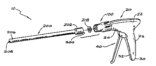
FIG. 1 shows a surgical instrument 10 in accordance with the
principles of the present invention, that can be used in laparoscopic surgical
15 procedures. It is appreciated that the instrument 10 is not limited to use inlaparoscopic procedures, but may be used in other surgical procedures as well, e.g.,
endoscopic procedures and the like. The instrument 10 comprises a handle 20
having a collar 100. The apparatus 10 also includes an ~tt~chment or end effector
200, shown separated and detached from the handle 20. It is noted that the handle
20 20 is reusable and can be used with other kinds of disposable end effectors (not
shown) of the type commonly used in laparoscopic or other surgical procedures.
Such end effectors may include ligating clip appliers, staplers, disposable scissors,
tackers, and the like.
As shown in FIGS. 1, 2 and 5, the handle 20 includes an external
housing 22 having an upper portion 24, a grip 26, and an internal chassis 28. The
housing 22 is preferably formed of separate corresponding half sections 30, 32,
made of a polycarbonate, ABS or other suitable material. The separate half sections
30, 32 may be attached together by fasteners, welding, adhesives, or other
att~c.hment means. The chassis 28 provides a support frame for the housing 22 and
a means of att~chm~nt for internal parts contained within the housing 22. The
WO 9C101'`'~ PCT/US95/08987
~ ~ 7 ~ 9 ~ ~
chassis 28 may be constructed of stainless steel or other suitable material. Thehandle 20 also includes an actuator 40 and a plunger 82.
The end effector 200 includes a proximal end 202 dçfining a
proxin,al opening 204 and a distal end 206 defining a distal opening 208. The end
effector 200 includes a compressible member 218, such as a silicone elastomer or a
closed cell foam, that is preferably fastened to the proximal end 202, e.g., by an
adhesive. The distal end 206 of the end effector 200 is typically inserted into a body
cavity (not shown). The end effector 200 defines a lonP:it~l-lin~l axis, and when
assembled and in use, is mounted to the collar 100 of the handle 20 and extends
distally away from the collar 100. It is contemplated and within the scope of the
invention to construct the end effector 200 to be rotatable together with the collar
100 by means well known to those having ordinary skill in the art.
Referring to FIG. 2, a cross-sectional view of the handle 20 shows in
solid lines the actuator 40 in a preactuated, at-rest position, and shows in phantom
lines the actuator 40 in a fully actll~ted position. The range of movement of the
actuator 40 is indicated by the arrow in phantom lines.
The actuator 40, as shown in FIG. 2, includçs a lever 42 which
extends away from the chassis 28 and is spaced a ~ t~nce from the grip 26 when
the actuator 40 is in the preactu~ted at-rest condition. The actuator 40 also
incllldes a middle portion 44 that is integrally formed with and extends from the
lever 42. The middle portion 44 has a generally circular shape and inc.ludec a first
extension 46, a second extension 48, and a plurality of teeth 50. The teeth 50
comprise substantially tri~ng~ r-shaped ridges. In a plerelled embodiment, the
teeth 50 are spaced along a portion of the periphery of the middle portion 44 behind
the first and second extensions 46, 48, i.e., the teeth 50 are positioned in a different
plane than the first and second extensions 46, 48. In the prefelled embodiment, the
middle portion 44 comprises two parts fastened together by fasteners 51 with thefirst part having the extensions 46, 48 and the second part having the teeth 50.
-10-
W0 96/04856 ~ 1 ~ 3 ~ 9 7 PCTIU~,95108987
The middle portion 44 of the actuator 40 is pivotally secured to the
chassis 28 by a first pivot pin 52 for pivotal movement of the lever 42 toward and
away from the grip 26. The actuator 40 also inchldes a head portion 54 which is
integrally forrned with the middle portion 44 and extends upwardly from the middle
- portion 44. The head portion 54 is positioned within the upper portion 24 of the
housing 22. In a pre~elled embodiment, the head portion 54 is adapted to fit within
a slot 56 formed in the plunger 82:
The actuator 40 also incl~ldes a ratchet assembly 60. With reference
to FIGS. 3-4, the ratchet assembly 60 includes a ratchet pawl 62 having a first leg
64 and a second leg 66. The first leg 64 and the second leg 66 are located generally
perpendicular to each other but extend in di~elenl planes, such that the first leg is in
the same plane as the ratchet teeth 50 and the second leg is in the same plane as the
first and second extensions 46, 48. The ratchet pawl 62 is pivotally mounted to the
chassis 28 of the handle 20 via a second pivot pin 68. The ratchet assembly 60 also
inc.llldes a ratchet spring 70 having a top end 72 and a bottom end 74. The top end
72 of the ratchet spring 70 is preferably attached to the free end of the first leg 64 of
the ratchet pawl 62. The bottom end 74 of the ratchet spring 70 may be att~hed to
the chassis 28 or to an adjustment bracket 76 mounted on the chassis 28.
To actuate the actuator 40, a user grasps the lever 42 and squeezes it
toward the grip 26 of the housing 22. Upon actuation of the actuator 40 (see FIG.
3), the first leg 64 of the ratchet pawl 62 sequentially engages and slides past each
of the ratchet teeth 50. The engagement of the teeth 50 with the first leg 64 of the
ratchet pawl 62 prevents the lever 42 from returning to its original position during
actuation of the handle 20, in the event the lever 42 is released by the operator.
Such a feature ensures proper use with a variety of possible end effectors. The
ratchet pawl 62 is biased toward the teeth 50 by the resilient ratchet spring 70. The
engagement of the ratchet pawl 62 with the ratchet teeth 50 provides audible
wo 96/04856 PCT/US95/08987
confirmation that the actuator 40 is being ~ct-l~ted as the operator will hear a series
of progressive audible clicking sounds.
FIG. 4 shows the actuator 40 and ratchet assembly 60 in a fillly
5 ~ct~l~ted position. The lever 42 is pulled toward the chassis 28, as shown by arrow
A, until it is adjacent the chassis 28. The head portion 54 is moved distally forward,
moving the plunger 82 for~vard, as shown by arrow B. Upon complete actuation,
the actuator 40 contacts a first actuator stop 78 attached to the chassis 28. The first
actuator stop 78 limits or prevents any further ac.tu~tinP movement by the actuator
10 40 in the counterclockwise direction. Upon release of the actuator 40 back to its
original position, the actuator 40 contacts a second actuator stop 80 ~tt~ched to the
chassis 28 (see FIG. 2). The second actuator stop 80 limits or prevents any further
movement by the actuator 40 in the clockwise direction. The stops 78, 80, are
att~ched to the chassis 28 and are configured and dimensioned for specific
15 engagement with the extending head portion 54 of the actuator 40 in a manner to
thereby limit the pivotal movement of the actuator 40 in both directions.
Referring again to FIG. 4, upon complete actuation of the actuator
40, the second extension 48 engages the second leg 66 of the ratchet pawl 62, so20 that the ratchet pawl 62 pivots in a clockwise direction, as indicated by arrow C.
The ratchet spring 70 is thus moved over the pivot center of the ratchet pawl 62,
the pivot center being that point where the second pivot pin 68 is mounted. The
movement of the ratchet spring 70 over center prevents the first leg 64 of the
ratchet pawl 62 from eng~PinSg the ratchet teeth 50. The actuator 40 can then freely
25 return to its original position. Upon release of the lever 42 back to its original
pre~c.t~l~ted position, the first extension 46 çng~sges the second leg 66 of the ratchet
pawl 62 and pivots the ratchet pawl 62 in a counterclockwise direction back to its
original position, so that the first leg 64 is again in a position to engage the teeth 50
(see FIG. 2). Thus, the act~l~ting mech~ni.sm of the present invention allows an30 operator to squeeze the lever 42 toward the grip portion 26 while m~i"~ ,i"g all
intermediate positions, in the event the operator releases the lever prior to
~ W096J048s6 2 ~ ~ ~ g ~ 7 PCTIUS95/08987
completion of the stroke. Then, once the lever has been fully actuated, the ratchet
pawl is disengaged and the operator is free to move the lever through all positions
between the at-rest position and the fully actuated position.
Referring still to FIGS. 2-4, the plunger 82 is shown in various
stages of actuation. The plunger 82 includes a Inngituflin~lly ~Yt~.n(lin~ rod 84 and
a support member 86 at the p~o~i"~al end of the rod. The support member 86 has
the slot 56 for receiving the head portion 54 of the actuator 40. The plunger 82 is
axially oriented to both the collar 100 and the end effector 200 and is capable of
moving axially and longitudin~lly through the interior of both the collar 100 and the
end effector 200. Upon actuation of the handle 20, the actuator 40 engages the
plunger 82 and moves it distally forward. Upon complete actuation and subsequent release of the actuator 40, a plunger spring 88 urges the plunger 82 back to its
original position
With reference to FIGS. 2 and 5, the assembly of the housing 22, the
actuator 40, the plunger 82 and the collar 100 will now be further described. In that
the housing includes two symmetrical half sections 30, 32, only the half section 32
will be described, it being appreciated that the half section 30 is of the same
construction. The half section 32 in~ des a longitutlin~l slot 90 for locating a wing
92 of the support member 86 of the plunger 82, thus permitting the plunger 82 to be
guided longit~l~in~lly within the handle. The half section 32 also includes a mount
94 for supporting an inner member 102 of the collar 100. The mount in~l~-des four
transverse walls 96 A, B, C, D for cradling the inner member 102 of the collar 100.
In particular, the inner member has a flange 104 that is located between the first and
second transverse walls 96A, B to prevent lonsgit~ldin~l movement of the inner
member. The inner member also includes three cylindrical portions 106A, B, C,
with cylindrical portion 106B having a smaller diameter than cylindrical portions
106A, C. Cylindrical portion 106B is cradled by notches in transverse walls 96C, D.
Preferably, cylindrical portions 106A, C engage the transverse walls 96C, D to
further prevent longitudinal movement of the inner member 102 of the collar.
-13-
W096/048!;6 . PCT/US95/08987 ,~
The inner member 102 of the collar also has an opening 108
therethrough for receiving the plunger 84. A snap ring (not shown) may be fixed to
the plunger to prevent separation of the plunger from the inner member 102 during
5 assembly of the remainder of the instrument.
With reference to FIG. 5, it should be appreciated that the handle 20
has a modular construction that f~rilit~tes cleaning and repl~cçrnent of individual
components. In particular, the half sections 30, 32, the chassis 28 and actuator 40,
the plunger 82 and the collar 100 may all be easily disassembled from each otherand cleaned.
With reference to FIGS. 6-8, the collar 100 and the means for
~tt~ching the end effector 200 to the collar 100 will now be described. The collar
15 100 is substantially cylindrical in shape and defines a longitudinal axis. The collar
100 provides a connection between the proximal end 202 of the end effector 200
and the handle 20. The collar 100 of the present invention can be used with a
variety of conventional end effectors of the type commonly used in laparoscopic
surgical procedures. Such end effectors may include ligating clip appliers, staplers,
20 disposable scissors, tackers, and the like, and is not limited to use with one specific
end effector. The end effectors may be disposed of after each use. The collar 100
provides the user with the ability to attach and detach an end effector to a handle
with a single translational snap-on or snap-off motion and without the need for
additional rotational motions. The plefel.ed embodiment of the present invention25 includes a collar 100 that provides a connection between a disposable laparoscopic
end effector and a reusable laparoscopic handle.
The collar 100 includes the inner member 102, referred to above,
and an outer member 110. The inner member 102 also inc.llldes a barrel portion 112
30 that is located within the outer member 110 distally of the third cylindrical portion
106C. The barrel portion includes an end wall 114 and a generally cylindrical,
-14-
~ Wo 96/048S6 2 ~ 7 3 ~ ~ ~ PCTIUSg5l08g87
-
lon~itudin~lly extending, wall 116 formed from four spaced apart arcuate portions
118. The end wall 114 has a greater diameter than the cylindrical wall so as to form
an annular shoulder 119 that supports an end of a spring 148, which will be
described in more detail later.
s
Ext~nrlin~ longitudinally and distally from the end wall 114 are four
cantilever fingers 120. Each cantilever finger is located in the space between
adjacPnt arcuate portions. Preferably, the arcuate portions assist in supporting the
fingers in the circull,îe,e"Lial direction. It will be appreciated upon a further
discussion of the operation of the cantilever fingers, that more or less than four
fingers may be used and that the arcuate portions may be closely adjacent the
fingers or omitted entirely.
Each cantilever finger has a mid-section 122 that projects radially
inwardly and distally to form a ramp surface 124. At the distal end of the ramp
surface, the finger projects distally, then radially outwardly and proximally to form a
hook portion 126 at a distal end 128 ofthe finger. The fingers are resilient so as to
be flexible radially inwardly from their normal or at rest position. The fingers also
have memory and return to their rest positions when the flexing force is released.
The inner member of the collar is preferably made of stainless steel, incl~ in~ the
fingers which are dimensioned to provide the desired resilient properties.
The outer member 110 of the collar includes an interior annular
surface 130 dçfining a proximal wall 132, a mid-wall 134 and a distal wall 136. The
l~lox~llal wall has an annular groove 138 formed therein to receive a snap ring 140
to prevent separation of the outer member from the inner member after assembly.
The mid-wall has a smaller di~meter than the proximal wall, forming a shoulder 142.
Between the mid-wall and distal wall is an annular ridge 144 having a ramp surface
146 configured to engage the ramp surface 124 of the inner member 102 upon
relative longitudin~l movement of the inner and outer members. A collar spring 148
is located radially between the inner and outer members and is biased between the
W096104856 PCT/US95/08987 ~
~3~7
shoulder 142 of the outer member and the shoulder 119 of the inner member so as
to urge the outer member distally relative to the inner member. Preferably, an outer
surface 150 of the outer member 110 has a plurality of radial protrusions 152 tof~c.ilit~te the gripping and pulling of the outer member 110 toward the handle 20.
s
Next, the procedure for att~hing and det~ching the end effector to
and from the collar will be described. With reference again to FIGS. 6-8, it is seen
that the proximal end 202 of the end effector has a radially inwardly directed
annular flange 154 onto which is affixed the conlplessible member 218. To attach10 the end effector to the collar, a user simply inserts the proximal end 202 of the end
effector into an opening 156 at the distal end of the collar until the conlplessible
member 218 or flange 154 contacts the hook portions 126 of the cantilever fingers
120. Further proximal movement of the end effector 200 results in the hook
portions 126 deflecting radially inwardly until the end effector is inserted sufficiently
15 to permit the hook portions to snap over an interior edge 158 of the annular flange
154, at which point the hook portions return to their undeformed positions. Thismovement and subsequent snapping of the cantilever fingers 120 against the annular
flange 154 ofthe end effector provides an audible "click" to indicate to the user that
the end effector 200 is securely attached to the collar 100.
In the prt:îe..ed embodiment, the hook portions 126 have angled
faces 160 upon which the annular flange 154 of the end effector rides, causing the
flexing of the hook portions. It will be appreciated, however, that the annular
flange may have the angled face and the hook portions would then ride along the
angled face of the flange until passing over the interior edge 158 of the flange and
~-appil~g back to their undeformed positions.
In the ple~lled embodiment, the elastomer or closed cell foam
portion 218 is compressed between the annular ridge 144 of the outer member 110
ofthe collar and the hook portions 126 ofthe cantilever fingers 120 to create a load
(see FIG. 7). This provides a firm connection with no slop or looseness and also
-16-
~ wo 96/04856 ~ ~ 7 3 ~ ~ 7 PCTIUS95/08987
automatically ejects the end effector 200 from the collar 100 when it is desired to
detach the end effector, as will be described below.
With reference to FIG. 8, the end effector 200 is detached from the
collar 100 by pulling the outer member 110 of the collar proximally against the
force ofthe spring 148. This causes the ramp surface 146 on the annular ridge 144
of the outer member l 10 to interface the ramp surfaces 124 of the cantilever fingers
120, causing the fingers to deflect radially inwardly. When the fingers are flexed
sufficiently inwardly to permit the hook portions 126 to clear the interior edge 158
of the flange, the co~ )les~ible member 218 will expand, pushing the end effector
200 distally a sufficient di~t~nce to prevent re-engagement of the fingers 120 to the
annular flange 154. The user may then release the outer member l 10, which returns
to its original position due to the biasing force of the spring, and remove the end
effector from the collar or simply allow gravity to let the end effector fall out of the
distal opening 156 of the collar.
It can be seen from the above that the collar 100 of the present
invention allows a user to attach the end effector 200 to the collar 100 with a single
translational snap-on motion that requires no additional manipulation, such as arotational movement. The end effector can also be detached using one hand. For
example, when the instrument is resting on a table, a user may press the palm of the
hand on the handle 20 and pull the collar 100 toward the palm with the fingers of
the same hand. As noted above, the end effector will eject from the collar due to
the expansion force of the con.pl essible member.
It will be appreciated that the specific connection meçh~ni~m
described above may be varied in many ways and yet obtain the benefits taught
herein. Alternative embodiments could vary the location of the end effector flange,
the cantilever fingers and the ramp surfaces.
W096/04856 PCT/US95/08987
S~3~7
With the end effector attached to the collar, the surgical instrument
may now be actuated to perform its intended function or functions. With reference
to FIG. 9A, the end effector 200 is actuated by the longitll~in~l movement of the
plunger 82 through the collar 100 into engagement with an actuating member 304
or ~ctu~ting members 304, 306 associated with the end effector. In the plert~ed
embodiment, the end effector 200 includes an outer support tube 302, the first
actl-~tin~ member 304, the second ~ctl-~ting member 306, a spring support 308 and
first and second ~ctu~ting member springs 310, 312. The outer tube is plefe,~blymade from ABS or polycarbonate.
The first ~tu~ting member 304 includes a distal portion 314 and a
proximal portion 316. The distal portion is concentrically located inside the outer
support tube and has a first cylindrical portion 318 and a second cylindrical portion
320 located proximally thereto. The second cylindrical portion has a larger
diameter than the first cylindrical portion, thus forming an annular wall 321 for
çng~gin~ one end of the first ~ctu~ting member spring 310.
The proximal portion 316 ofthe first actuating member 304 includes
a bearing portion 322 and a deflectable portion 324. The bearing portion is
proximal to and integral with the second cylindrical portion 320. Preferably, the
bearing portion has a half-cylinder shape, an outer surface 326 of which conforms
to and bears against an inside surface 328 of the outer support tube 302.
Preferably, the deflectable portion 324 is in the form of a cantilever that is integral
to and extends proximally from the bearing portion. The cantilever may have a
partial cylindrical shape wherein an outer wall 332 of the cantilever is spaced from
the inside surface 328 of the outer support tube 302. A proximal end 334 of the
cantilever has a radially inwardly disposed lip 336 that is located in cont~cting
~lignm~.nt with the distal end of the plunger 82 upon movement of the plunger in a
distal direction.
~73~7
~, WO 96/04856 PCTIUS95108987
The first actll~ting member 304 is preferably made of ABS or
polycarbonate. The cantilever may be made of the same material, but is
dimensioned to provide resiliency such that the unsupported ploxilllal end 334 of
the cantilever may be flexed radially outward, yet return to its original position in
5 the absence of the flexing force.
The second act~ting member 306 includes a distal portion 338 and
a proximal portion 340. The distal portion has a split tube portion 342 and a larger
diameter, tubular portion 344 located proximally thereto, forming an annular wall
346 for eng~ing one end of the second actl.atin~ member spring 312. The distal
portion of the second act~-~ting member is concentrically located inside the outer
support tube 302 with the first cylindrical portion 318 ofthe first act~.~tin~ member
304 passing inside and through the split tube portion 342 of the second actuating
member 306.
The proximal portion 340 of the second act~l~ting member 306 is
proximal to and integral with the tubular portion 344 and, preferably, has a half-
cylinder shape, an outer surface 348 of which bears against the inside surface 328 of
the outer support tube 302. It will be appreciated that the half -cylinder shape of
20 the bearing portion 322 of the first act~.~ting member and the halfcylinder shape of
the proximal portion 340 of the second actl~ating member may be located in
opposed relationship to each other to form a sliding surface 350, permitting relative
movement between them.
The half-cylindrical proximal portion 340 of the second ~ctl.~ting
member includes a transverse wall 352 that extends radially inwardly. The traverse
wall is located distally of a proximal end 354 of the proximal portion and,
preferably, incl~ldes a ramp surface 356 at its radially inward end. The ramp surface
is located in cont~cting ~ nm~.nt with the lip 336 of the cantilever 324 upon
movement of the first ~ct~.~ting member 304 in the distal direction. The second
-19-
WO 96/04856 . . PCT/US95/08987 ,~
3 .~ 9 ~
act~l~ting member 306 is preferably made of ABS, polycarbonate, or other suitable
material.
With reference also to FIG. 10, the spring support 308 is f~ctene(l to
S the inside surface 328 of the outer support tube, e.g., by welding, f~tent?rs or
adhesive, or may be molded with the outer support tube. The spring support may
be made of metal, plastic or other suitable material. The spring support defines a
central bore 358 for receiving the first cylindrical portion 318 of the first act~l~ting
member and one or more arcuate slots 360 for receiving the split tube portion 342
10 of the second actu~ting member. The first act~tin~ member spring is located
around the first cylindrical portion of the first ~ctu~ting member and is biasedbetween the annular wall 321 of the first actuating member and the spring support.
The second actu~ting member spring is located around the split tube portion 342 of
the second act~lating member and is biased between the annular wall 346 of the
second act~lating member and the spring support. Because the spring support is
fixed to the outer support tube, both the first and second act~l~ting member springs
will urge the first and second act~l~ting members proximally.
The actuation of the end effector will now be described with respect
to FIGS. 9A-9E. FIG. 9A shows the plunger 82, the first actuating member 304
and the second ~ct~-~ting member 306 in their original, pre-ac.tu~ted positions. The
first actu~ting member 304 is mounted for longit~ldin~l movement within the outer
support tube 302 and is in cont~ctinn longitll-lin~l alignment with a distal end 330 of
the plunger 82. When the lever portion 42 of the actuator 40 is squeezed toward
the grip 26 (see FIG. 2), the plunger 82 moves distally forward, and the distal end
330 of the plunger 82 engages the proximal end 334 of the deflectable portion 324
ofthe first actuating member 304 and moves the first actuating member 304 distally
fo,wal-d a desired distance. For example, in a clip applier, the desired distance
traveled by the first actu~ting member 304 is a distance sufficient to advance a clip
(not shown) into the jaws of the clip applier.
-20-
WO 9"04~'~ 2 ~ 9 9 ~ P~TIUS95J08987
With reference to FIG. 9B, the plunger 82 moves the first actll~tinSg
member 304 to a position where the lip 336 of the deflectable portion 324 engages
the ramp 356 of the transverse wall 352 of the second actn~ting member 306. The
lip 336 and the transverse wall 352 are positioned in cont~ctin~ alignment relative
to each other and are configured, such that distal movement of the plunger 82
results in their engagement.
With reference to FIG. 9C, further distal movement of the plunger
82 results in the lip 336 sliding down the ramp 356, causing the proximal end 334 of
the deflectable portion 324 to move radially outwardly and out of longitlldin~l
alignment with the plunger 82. Specifically the lip 336 moves against the ramp
surface 356 until it is forced below the ramp surface 356, rii~t?nP~ginP the
deflectable portion from the distal end 330 of the plunger 82. At this point, the
spring force of the first actuating member spring 310 urges the first act~l~tingmember 304 prox"l,ally to its original starting position (see FIG. 9D).
Referring to FIG. 9D, the first actuating member 304 is shown
tli~eng~ged from the plunger 82 and moved radially out of the way, with the
transverse wall 352 of the second act-l~tinsJ member 306 now in cont~cting
longit~ldin~l alignment with the distal end 330 of the plunger 82. With reference to
FIG. 9E, the distal end 330 ofthe plunger 82 engages the transverse wall 3~2 ofthe
actuator 306 and moves it distally a desired distance. For example, in a clip applier,
the desired dict~nce traveled by the second ~c.tu~ting member 306 is a di~t~nce
sufficient to engage and close the jaws (not shown) of the clip applier.
Once the second act~l~ting member 306 has been moved the
sufficient distance, the actuator 40 may be released and the plunger 82, the
deflectable portion 324 of the first act~tino member 304, and the second act~l~tinP
member 306 returned to their original starting positions. In particular, the plunger
spring retracts the plunger into the handle, the second ?~ct~ tinp member spring 312
urges the second actuating member back to its original starting position and the
WOg6/04856 ~ PCT/US95/08987
~1 ~
deflectable portion 324 flexes back into longitudinally contacting alignment with the
plunger 82 (see FIG. 9A).
Thus, the surgical apparatus 10 of the present invention incllldes a
5 universal handle 20 that can be used with a variety of di~t;nl end effectors,
inclllrling single action end effectors that perform a single function and double
action end effectors that perform two functions. The surgical instrument incllldec
an actuator 40 that converts a single plunger motion into two separate and
independent actuator motions required for actuating a first actuating member 304and a second actuating member 306. A ratcheting assembly 60 is also provided that
locks the instrument in succeccive positions during actuation, but frees the actuator
once the end effector operation has been completed. Finally, an easy to use
~tt~chment mech~ni.cm is provided for securely and quickly attaching and det~çhing
the disposable end effectors.
While the invention has been described with reference to pr~el.ed
embo~im~ntc, it will be understood by those skilled in the art that various changes
may be made and equivalents may be substituted for elements thereof without
departing from the broader aspects of the invention. Also, it is inten~1ed that broad
20 claims not specifying details of a particular embodiment disclosed herein as the best
mode contemplated for carrying out the invention, should not be limited to such
details.