Language selection

Search

Patent 2174057 Summary

Third-party information liability

Some of the information on this Web page has been provided by external sources. The Government of Canada is not responsible for the accuracy, reliability or currency of the information supplied by external sources. Users wishing to rely upon this information should consult directly with the source of the information. Content provided by external sources is not subject to official languages, privacy and accessibility requirements.

Claims and Abstract availability

Any discrepancies in the text and image of the Claims and Abstract are due to differing posting times. Text of the Claims and Abstract are posted:

  • At the time the application is open to public inspection;
  • At the time of issue of the patent (grant).
(12) Patent: (11) CA 2174057
(54) English Title: HOUSING FOR A RETRACTABLE CORD MECHANISM
(54) French Title: LOGEMENT DE MECANISME D'ENROULEMENT DE CORDON
Status: Term Expired - Post Grant Beyond Limit
Bibliographic Data
(51) International Patent Classification (IPC):
  • B65H 75/34 (2006.01)
  • B65H 75/40 (2006.01)
  • H02G 11/02 (2006.01)
(72) Inventors :
  • NESS, RANDOLPH PETER (Canada)
(73) Owners :
  • THE REEL-THING INNOVATIONS INC.
  • THE REEL-THING INNOVATIONS INC.
(71) Applicants :
  • THE REEL-THING INNOVATIONS INC. (Canada)
  • THE REEL-THING INNOVATIONS INC. (Canada)
(74) Agent: NATHAN V. WOODRUFFWOODRUFF, NATHAN V.
(74) Associate agent:
(45) Issued: 2002-09-10
(22) Filed Date: 1996-04-12
(41) Open to Public Inspection: 1997-06-19
Examination requested: 1998-04-02
Availability of licence: N/A
Dedicated to the Public: N/A
(25) Language of filing: English

Patent Cooperation Treaty (PCT): No

(30) Application Priority Data:
Application No. Country/Territory Date
08/574,385 (United States of America) 1995-12-18

Abstracts

English Abstract

A housing for a retractable cord mechanism includes a first body, a second body and a coupling for securing the first body to the second body in a water tight manner to create a composite body with an interior cavity. The composite body has a snout-like projection with an opening positioned at a terminus of the snout-like projection. The composite body is mounted with the snout-like projection angled downwardly such that any water splashed up into the interior cavity of the composite housing drains by force of gravity out of the opening at the terminus of the snout-like projection.


French Abstract

Un logement de mécanisme d'enroulement de cordon comprend un premier corps, un deuxième corps et un raccord permettant de fixer le premier corps au deuxième corps de manière étanche, afin de créer un corps composite avec une cavité intérieure. Le corps composite présente une saillie en forme de bec, avec une ouverture positionnée au niveau d'une extrémité de la saillie en forme de bec. Le corps composite est fixé avec la saillie en forme de bec inclinée vers le bas, de telle sorte que l'eau éclaboussée dans la cavité intérieure du logement composite se vide par la force de la gravité hors de l'ouverture se trouvant au niveau de l'extrémité de la saillie en forme de bec.

Claims

Note: Claims are shown in the official language in which they were submitted.

7
THE EMBODIMENTS OF THE INVENTION IN WHICH AN EXCLUSIVE PROPERTY
OR PRIVILEGE IS CLAIMED ARE DEFINED AS FOLLOWS:
1. A retractable cord assembly mechanism, comprising:
a first body;
a second body;
means for securing the first body to the second body
in a water tight manner to create a composite body with an
interior cavity, the composite body having a snout-like
projection with an opening positioned at a terminus of the
snout-like projection; and
means for mounting the composite body with the snout-
like projection angled downwardly such that any water splashed
up into the interior cavity of the composite body drains by
force of gravity out of the snout-like projection; and
the composite body including a water resistant
secondary compartment in which a circuit breaker is disposed,
the circuit breaker being coupled to wiring of a cord
positioned on a retracting mechanism.
2. The assembly as defined in Claim 1, wherein the composite
body has a mounting arrow indicating the correct mounting
orientation.
3. The assembly as defined in Claim 1, wherein a closure
member is mounted on the cord, the closure member blocking the
opening at the terminus of the snout-like projection when the
cord is in a retracted position, the closure member serving as
a stop to prevent the cord from being completely retracted into
the interior cavity of the composite body when the cord is
retracted.
4. The assembly as defined in Claim 1, wherein the means for
mounting the composite body includes a plurality of mounting
tabs with mounting bars extending between the mounting tabs,
one of the mounting bars being positioned on the snout-like
projection.

8
5. A retractable cord assembly, comprising:
a first shell form body having a form defining
sidewall that includes a snout-like projection, a cord
withdrawal opening extending through the sidewall at a terminus
of the snout-like projection, the sidewall having a top
peripheral edge;
a second shell form body having a form defining
sidewall that includes a snout-like projection, a cord
withdrawal opening extending through the sidewall at a terminus
of the snout-like projection, the sidewall having a top
peripheral edge;
means for securing the sidewall of the first body
adjacent the top peripheral edge to the sidewall of the second
body adjacent the top peripheral edge in a water tight manner,
thereby mating the first body with the second body to create
a composite body with an interior cavity in which a cord
retracting mechanism and associated electrical wiring, and
electrical connections are positioned, the composite body
having a composite snout-like projection having a composite
terminus with a composite cord withdrawal opening; and
means for mounting the composite body with the
composite snout-like projection angled downwardly such that any
water splashed up into the composite body drains by force of
gravity out of the composite snout-like projection; and
the first body including a secondary dividing wall
immediately adjacent to the snout-like projection, the second
body including a secondary dividing wall immediately adjacent
to the snout-like projection, means for coupling the secondary
dividing wall of the first body with the secondary dividing
wall of the second body to form a water resistant secondary
compartment upon the composite body being formed, a circuit
breaker being disposed in the secondary compartment with a
reset switch projecting from the secondary compartment into the
interior cavity, the circuit breaker being coupled to the
associated electrical wiring of a cord positioned on the cord
retracting mechanism, an access opening with a removable
closure being provided through one of the snout-like

9
projections thereby providing access to the reset switch to
manually reset the circuit breaker.
6. The assembly as defined in Claim 5, wherein the top
peripheral edge of the sidewall of the first body abuts with
the top peripheral edge of the sidewall of the second body, a
female coupling being positioned in an exterior surface of the
sidewall of one of the first body and the second body adjacent
the top peripheral edge, and a male coupling being provided on
a projecting flange on an interior surface of the sidewall of
the other of the first body and the second body, the male
coupling mating with the female coupling to provide a water
resistant seal.

Description

Note: Descriptions are shown in the official language in which they were submitted.


z~7~o~~
1
TITLE OF THE INVENTION:
Housing for a retractable cord mechanism
NAME OF INVENTOR:
Randolph Peter Ness
FIELD OF THE INVENTION
The present invention relates to a housing for a
retractable cord mechanism and, in particular, one intended to
be mounted on a motor vehicle.
BACKGROUND OF THE INVENTION
The utility of retracting mechanisms for extension cords
has long been recognized. As a consequence, they are being
used for an infinite variety of applications. The use of such
mechanisms in outdoor applications has been limited by the lack
of an adequate housing. The function of the housing is to
prevent water from getting into the retracting mechanism and
shorting out electrical connections. In order to be effective
for outdoor use, a housing must as a minimum requirement be
able to be subjected to continuous drenching by rain and still
keep the retracting mechanism and electrical connections dry.
When a housing is mounted onto a motor vehicle, a further
problem encountered is that water on the road splashes up and
into the housing.
SUI~IARY OF THE INVENTION
What is required is a housing for a retractable cord

CA 02174057 1999-O1-12
2
mechanism that is better suited for mounting on a motor
vehicle.
According to the present invention there is provided a
housing for a retractable cord mechanism which includes a first
body, a second body and means for securing the first body to
the second body in a water tight manner to create a composite
body with an interior cavity. The composite body has a snout-
like projection with an opening positioned at a terminus of the
snout-like projection. Means is provided for mounting the
composite body with the snout-like projection angled downwardly
such that any water splashed up into the interior cavity of the
composite housing drains by force of gravity out of the opening
at the terminus of the snout-like projection.
20
With the housing, as described above, water splashing into
the interior cavity of the housing is no longer a problem, as
the snout-like projection provides a suitable means for
allowing such water to drain.
Although beneficial results may be obtained through the
use of the housing, as described above, another problem
commonly encountered is that of heat build up due to excessive
electrical current flow. Even more beneficial results may,
therefore, be obtained when the composite body includes a
secondary water resistant compartment in which a circuit
breaker is disposed. The circuit breaker is coupled to wiring
of a cord positioned on a retracting mechanism.
BRIEF DESCRIPTION OF THE DRAWINGS
These and other features of the invention will become more
apparent from the following description in which reference is
made to the appended drawings, wherein:
FIGURE 1 is a perspective view of a housing constructed
in accordance with the teachings of the present invention.

CA 02174057 1999-O1-12
3
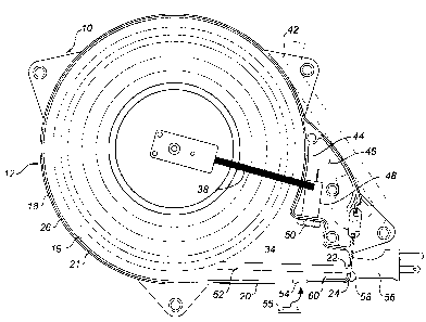
FIGURE 2 is a side elevation view in section of the
housing illustrated in FIGURE 1.
FIGURE 3 is an end elevation view in section of the
housing illustrated in FIGURE 1.
FIGURE 4 is a perspective view of the housing illustrated
in FIGURE 1 in the process of being mounted to a truck bumper.
FIGURE 5 is a side elevation view, partially in section,
of the housing illustrated in FIGURE 1 mounted to a truck
bumper.
DETAILED DESCRIPTION OF THE PREFERRED EMBODIMENT
The preferred embodiment, a housing for a retractable cord
mechanism generally identified by reference numeral 10, will
now be described with reference to FIGURES 1 through 5.
Referring to FIGURE 3, housing 10 includes a first shell
form body 12 and a second shell form body 14 which are joined
together to form a composite body, generally indicated by
reference numeral 16. Body l2 and body 14 are mirror images
of each other. Referring to FIGURE 2, body 12 is illustrated.
It will be appreciated that body 14 is similar in construction.
Body 12 has a form defining sidewall 18 that includes a snout-
like projection 20. Sidewall 18 has an interior surface 19 and
an exterior surface 21. An opening 22 extends through sidewall
18 at a terminus 24 of snout-like projection 20. Sidewall 18
has a top peripheral edge 26. Referring to FIGURE 3, sidewall
18 of first body 12 adjacent top peripheral edge 26 is secured
to sidewall 18 of second body 14 adjacent top peripheral edge
26. The preferred means of securing first body 12 to second
body 14 in a water tight manner involves abutting top
peripheral edge 26 of sidewall 18 of first body 12 with top
peripheral edge 26 of sidewall 18 of second body 14. A female
coupling 28 is positioned in exterior surface 21 of sidewall
18 of second body 14 adjacent top peripheral edge 26. A male
coupling 30 is provided on interior surface 19 of sidewall 18

CA 02174057 1999-O1-12
4
of first body 12. Male coupling 30 is positioned on a flange
portion 32. Flange portion 32 of second body 14 overlies first
body 12 enabling male coupling 30 to mate with female coupling
28 to provide a water resistant seal. First body 12 is mated
with second body 14, as described, to form composite body 16.
Referring to FIGURE 3, composite body 16 has an interior cavity
34 in which a cord retracting mechanism, generally indicated
by reference numeral 36 is positioned, together with associated
electrical wiring and electrical connections 38, as illustrated
in FIGURE 2. Cord retracting mechanism 36 includes a rotatably
mounted spool 40. Spool 40 is biased by a biasing spring (not
shown). A plurality of pairs of ear-like planar mounting tabs
42 and 43 are provided for mounting composite body 16 to a
motor vehicle. Tabs 42 project from first body 12. Each of
tabs 42 is positioned parallel to a corresponding tab 43
projecting from second body 14, thereby forming a pair.
Referring to FIGURE 3, a tubular mounting bar 45 extends
between tab 42 and tab 43. Each tubular mounting bar 45 has
a mounting aperture 47 extending therethrough, as illustrated
in FIGURE 2. It is important to note that snout-like
projection 20 is intended to be angled downwardly. The
installation instructions emphasize that fact and an arrow 23
is provided for the assistance of the user. The purpose of
snout-like projection 20 is to permit any water splashed up
into interior cavity 34 of composite body 16 to drain by force
of gravity out of a drain passage 60 at terminus 24 of snout-
like projection 20. Referring to FIGURE 2, first body 12
includes a secondary dividing wall 44 immediately adjacent to
snout-like projection 20. Second body 14 includes a similar
secondary dividing wall 44 immediately adjacent to snout-like
projection 20. Upon composite body 16 being formed, secondary
dividing wall 44 of first body 12 and secondary dividing wall
44 of second body 14 form a water resistant secondary
compartment 46. A circuit breaker 48 is disposed in secondary
compartment 46 with a reset switch 50 projecting from secondary
compartment 46 into interior cavity 34. Circuit breaker 48 is
coupled to wiring 38 of a cord 52 positioned on spool 40 of

217!~0~'~
retracting mechanism 36. An access opening 54 with a removable
closure 55 is provided through snout-like projection 20. This
provides access to reset switch 50 to manually reset circuit
breaker 48. Cord 52 has attached to it a plug 56. An end 58
5 of plug 56 serves as a closure member. End 58 blocks opening
22 at terminus 24 of snout-like projection 20 when cord 52 is
in a retracted position. End 58 also serves as a stop to
prevent plug 56 from being retracted into interior cavity 34
of composite housing 16 when placed in the retracted position.
The use and operation of housing 10 will now be described
with reference to FIGURES 1 through 5. Composite body 16 is
mounted by means of mounting tabs 42 and 43. Apertures 47
allow side mounting where suitable. The preferred manner of
mounting, however, is depicted in FIGURES 4 and 5. FIGURE 5
illustrates a truck bumper 62 having an interior side 64 and
an exterior side 66. Interior side 64 faces inwardly toward
the undercarriage of the vehicle. Exterior side 66 faces
outwardly and is visible to an observer. Truck bumper 62 has
mounting apertures 68. Housing 10 can be attached to mounting
apertures 68 by means of an attachment bracket 70 or a piece
of tie 72. Whether attachment bracket 70 or piece of tie 72
are used, attachment to housing 10 is by way of mounting bars
45 and apertures 47. It is to be noted that housing 10 is
mounted to truck bumper 62 with snout-like projection 20 angled
downwardly and plug 56 accessible from below truck bumper 62.
The male-female engagement provided by female coupling 28 and
male coupling 30 makes housing 10 sufficiently water tight that
it can withstand any drenching from above. Should water splash
through opening 22 from below, such water drains by force of
gravity back out of drain passage 60 due to the downwardly
inclined angle of snout-like projection 20. In order to
prevent water from splashing up through opening 22, end 58 of
plug 56 blocks opening 22 when cord 52 is in a retracted
position. Should a build up of heat occur, circuit breaker 48
will trip before any harm is done. Circuit breaker 48 may
subsequently be manually reset by removing removable closure

2I7~~~7
6
55 and extending a finger or screw driver through access
opening 54 in order to trip reset switch 50.
It will be apparent to one skilled in the art that
modifications may be made to the illustrated embodiment without
departing from the spirit and scope of the invention as
hereinafter defined in the Claims.

Representative Drawing
A single figure which represents the drawing illustrating the invention.
Administrative Status

2024-08-01:As part of the Next Generation Patents (NGP) transition, the Canadian Patents Database (CPD) now contains a more detailed Event History, which replicates the Event Log of our new back-office solution.

Please note that "Inactive:" events refers to events no longer in use in our new back-office solution.

For a clearer understanding of the status of the application/patent presented on this page, the site Disclaimer , as well as the definitions for Patent , Event History , Maintenance Fee  and Payment History  should be consulted.

Event History

Description Date
Inactive: Expired (new Act pat) 2016-04-12
Appointment of Agent Requirements Determined Compliant 2011-04-20
Inactive: Office letter 2011-04-20
Revocation of Agent Requirements Determined Compliant 2011-04-20
Small Entity Declaration Request Received 2008-04-08
Small Entity Declaration Determined Compliant 2008-04-08
Inactive: IPC from MCD 2006-03-12
Grant by Issuance 2002-09-10
Inactive: Cover page published 2002-09-09
Inactive: Final fee received 2002-06-12
Pre-grant 2002-06-12
Letter Sent 2001-12-17
Notice of Allowance is Issued 2001-12-17
Inactive: Approved for allowance (AFA) 2001-12-03
Amendment Received - Voluntary Amendment 1999-01-12
Inactive: Status info is complete as of Log entry date 1998-07-22
Letter Sent 1998-07-22
Inactive: Application prosecuted on TS as of Log entry date 1998-07-22
All Requirements for Examination Determined Compliant 1998-04-02
Request for Examination Requirements Determined Compliant 1998-04-02
Application Published (Open to Public Inspection) 1997-06-19

Abandonment History

There is no abandonment history.

Maintenance Fee

The last payment was received on 2002-04-08

Note : If the full payment has not been received on or before the date indicated, a further fee may be required which may be one of the following

  • the reinstatement fee;
  • the late payment fee; or
  • additional fee to reverse deemed expiry.

Please refer to the CIPO Patent Fees web page to see all current fee amounts.

Fee History

Fee Type Anniversary Year Due Date Paid Date
MF (application, 2nd anniv.) - small 02 1998-04-14 1998-04-02
Request for examination - small 1998-04-02
MF (application, 3rd anniv.) - small 03 1999-04-12 1999-02-18
MF (application, 4th anniv.) - small 04 2000-04-12 2000-02-23
MF (application, 5th anniv.) - small 05 2001-04-12 2001-02-08
MF (application, 6th anniv.) - small 06 2002-04-12 2002-04-08
Final fee - small 2002-06-12
MF (patent, 7th anniv.) - small 2003-04-14 2003-04-04
MF (patent, 8th anniv.) - small 2004-04-12 2004-03-02
MF (patent, 9th anniv.) - small 2005-04-12 2005-02-17
MF (patent, 10th anniv.) - small 2006-04-12 2006-02-08
MF (patent, 11th anniv.) - small 2007-04-12 2007-01-23
MF (patent, 12th anniv.) - small 2008-04-14 2008-04-08
MF (patent, 13th anniv.) - small 2009-04-13 2009-02-05
MF (patent, 14th anniv.) - small 2010-04-12 2010-02-23
MF (patent, 15th anniv.) - small 2011-04-12 2011-02-23
MF (patent, 16th anniv.) - small 2012-04-12 2012-03-08
MF (patent, 17th anniv.) - small 2013-04-12 2013-03-22
MF (patent, 18th anniv.) - small 2014-04-14 2014-04-11
MF (patent, 19th anniv.) - small 2015-04-13 2015-04-07
Owners on Record

Note: Records showing the ownership history in alphabetical order.

Current Owners on Record
THE REEL-THING INNOVATIONS INC.
Past Owners on Record
RANDOLPH PETER NESS
Past Owners that do not appear in the "Owners on Record" listing will appear in other documentation within the application.
Documents

To view selected files, please enter reCAPTCHA code :


To view images, click a link in the Document Description column. To download the documents, select one or more checkboxes in the first column and then click the "Download Selected in PDF format (Zip Archive)" or the "Download Selected as Single PDF" button.

List of published and non-published patent-specific documents on the CPD .

If you have any difficulty accessing content, you can call the Client Service Centre at 1-866-997-1936 or send them an e-mail at CIPO Client Service Centre.


Document
Description 
Date
(yyyy-mm-dd) 
Number of pages   Size of Image (KB) 
Abstract 1996-07-18 1 18
Cover Page 1997-06-19 1 17
Description 1996-07-18 6 255
Description 1999-01-12 6 250
Claims 1999-01-12 3 117
Drawings 1999-01-12 5 101
Cover Page 2002-08-07 1 47
Claims 1996-07-18 3 113
Drawings 1996-07-18 5 87
Representative drawing 2001-12-04 1 20
Representative drawing 1998-05-20 1 39
Reminder of maintenance fee due 1997-12-15 1 111
Acknowledgement of Request for Examination 1998-07-22 1 194
Commissioner's Notice - Application Found Allowable 2001-12-17 1 166
Fees 2013-03-22 1 155
Fees 2003-04-04 1 25
Correspondence 2002-06-12 2 81
Correspondence 2002-07-03 1 11
Fees 1999-02-18 1 37
Fees 2002-04-08 1 28
Fees 1998-04-02 1 44
Fees 2004-03-02 1 29
Fees 2005-02-17 1 27
Fees 2006-02-08 1 27
Fees 2007-01-23 1 26
Correspondence 2008-04-08 2 40
Fees 2008-04-08 2 39
Fees 2009-02-05 1 32
Fees 2010-02-23 1 200
Fees 2011-02-23 1 201
Correspondence 2011-03-31 3 155
Correspondence 2011-04-20 1 11
Correspondence 2011-04-20 1 15