Language selection

Search

Patent 2174086 Summary

Third-party information liability

Some of the information on this Web page has been provided by external sources. The Government of Canada is not responsible for the accuracy, reliability or currency of the information supplied by external sources. Users wishing to rely upon this information should consult directly with the source of the information. Content provided by external sources is not subject to official languages, privacy and accessibility requirements.

Claims and Abstract availability

Any discrepancies in the text and image of the Claims and Abstract are due to differing posting times. Text of the Claims and Abstract are posted:

  • At the time the application is open to public inspection;
  • At the time of issue of the patent (grant).
(12) Patent Application: (11) CA 2174086
(54) English Title: POSTS, BATTENS AND ACCESSORIES THEREFOR
(54) French Title: PIEUX, LATTES ET ACCESSOIRES ASSOCIES
Status: Deemed Abandoned and Beyond the Period of Reinstatement - Pending Response to Notice of Disregarded Communication
Bibliographic Data
(51) International Patent Classification (IPC):
  • B21D 05/14 (2006.01)
  • B21D 53/00 (2006.01)
  • B25D 01/16 (2006.01)
  • E04H 17/10 (2006.01)
  • E04H 17/20 (2006.01)
  • E04H 17/26 (2006.01)
  • F16G 11/00 (2006.01)
(72) Inventors :
  • JOYCE, KEVIN PATRICK (New Zealand)
  • INNES, STUART MARTIN (New Zealand)
  • INNES, RODNEY MITCHELL (New Zealand)
(73) Owners :
  • MANUKAU FIFTY LIMITED
(71) Applicants :
  • MANUKAU FIFTY LIMITED (New Zealand)
(74) Agent: MARKS & CLERK
(74) Associate agent:
(45) Issued:
(86) PCT Filing Date: 1994-10-14
(87) Open to Public Inspection: 1995-04-20
Availability of licence: N/A
Dedicated to the Public: N/A
(25) Language of filing: English

Patent Cooperation Treaty (PCT): Yes
(86) PCT Filing Number: PCT/NZ1994/000108
(87) International Publication Number: NZ1994000108
(85) National Entry: 1996-04-12

(30) Application Priority Data:
Application No. Country/Territory Date
248964 (New Zealand) 1993-10-15

Abstracts

English Abstract


A post and batten for fencing and other purposes which
is provided with an opening in one face to facilitate locking
engagement of a fastener thereto. Also described a hand post
driver to cushion shock during use. A standard drive
comprises a post tube, cross-bars and handles, these elements
forming a rigid frame. The present invention modifies this
arrangement by mounting a cap to the handles and interposing
coil springs between the upper cross-bar and the cap. A
solid plug is fixed in the end of post tube. There is no
connection between the end of the tube adjacent the cap and
the handles are free to slide in top-cross-bar. When the
tube is impacted on a post the post exerts pressure on the
plug and simultaneously the springs are extended cushioning
the blow and then almost instantaneously the end of the tube
is impacted by the cap providing supplementary downward
force.


French Abstract

Pieu ou latte pour clôtures et autres applications, dont l'une des faces (5) est pourvue d'une ouverture (6) facilitant la solidarisation d'un élément de fixation (11). Est également décrit un enfonce-pieu manuel destiné à amortir les chocs pendant l'utilisation. Un enfonce-pieu normal comporte un tube, des traverses et des manches, ces éléments formant un châssis rigide. On a modifié cette configuration en montant un élément terminal (35) sur les manches (34), et en interposant des ressorts hélicoïdaux (36) entre la traverse supérieure (33) et l'élément terminal (35). Un bouchon solide (37) est fixé dans l'extrémité du tube (32). L'extrémité du tube (32) qui est voisine de l'élément terminal (35) n'est pas reliée à celui-ci, et les manches (34) glissent librement dans la traverse supérieure (33). Lorsque le tube (32) vient heurter un pieu, le pieu exerce une pression sur le bouchon (37) et, au même moment, les ressorts s'étirent de manière à amortir le choc. Presque instantanément, l'extrémité du tube (32) est heurtée par l'élément terminal (35) de manière à créer un effort supplémentaire dirigé vers le bas.

Claims

Note: Claims are shown in the official language in which they were submitted.

THE CLAIMS DEFINING THE INVENTION ARE:
1. An elongate post having on at least one face an opening to which
attachments can be mude, said opening providing opposed inwardly
turned edges and means to facilitate locking engagement of a
fastener member therewith.
2. A post of claim 1 of substantially rectilinear cross-section.
3. A post as claimed in claim 1 or claim 2 wherein the inwardly turned
edges are serrated.
4. A post as claimed in any one of claims 1 to 8 wherein the serrated
edges are regular.
5. A post claimed in any one of claims 1 to 4 wherein the serrated
edges are of a generally saw-tooth configuration with the tips of each
coincident.
6. A post as claimed in any one of claims 1 to 5 wherein the inner faces
of the inwardly turned edges at the widest point are provided with a
surface which is substantially parallel with the said at least one
face.
7. A fence comprising a plurality of posts as claimed in any one of
claims 1 to 6, supporting a series of spaced fence wires, the fence
wires being secured to the posts by staples drives into the apertures
of the posts.
8. A fence as claimed in claim 7 wherein the staples are two-pronged
staples each prong being joined by a common limb and each staple
prong engaging with a separate socket of said at least one face.

9. A fence as claimed in claim wherein the locating face of said inner
edges is co-planar with the ridge of the spike of each staple prong.
10. A post as claimed in any one of claims 1 to 6 when secured to
structure to support a wall lining or such like of a building.
11. A method of manufacturing a post as claimed in any one of claims 1
to 6 comprising the steps of;
feeding an elongate plate to a roll forming apparatus, serrating side
edges of the elongate plate and shaping the plate into a box-section.
12. A method as claimed in claim 11 wherein said side edges are
shaped prior to being serrated.
13. A method as claimed in claim 11 or claim 12 wherein the serration
is achieved by a pair of complimentary toothed wheels.
14. A post driver comprising an elongate post tube, having an open end
and a closed end, a pair of spaced cross-bars fixed to the post tube
near its open and closed ends, a handle comprising a cap and two
hand grips which extend from the cap and which are slidingly
supported by a first cross-bar adjacent the closed end of the post tube
and fixed to the cross-bar adjacent the open end and resilient
compressible members extending between the cap and said first
cross-bar, the cap being spaced from the closed end of the post tube a
predetermined distance and capable of contact closed end of the post
tube when the post tube is impacted on a post.
15. A post substantially as wherein described with reference to the
accompanying drawings.

16. A fence substantially as herein described with reference to the
accompanying drawings.
17. A post driver substantially as herein described with references to the
accompanying drawings.
11

Description

Note: Descriptions are shown in the official language in which they were submitted.


217~086
wo ~5110372 PCr~Z94~010
Pos~s, ~3~ttens and An~e~o~ies Therefor
TEG1~ChL E~r~T.n
Thi.~ V~ n relate~ to po~ts, b~te~ a~d ~he like whi~h ha~e a n~ ber
of uses, one e2aInple being the constructio~ of pe~man nt or s~mi-
h per~npnt fenling
~3A~ GRoU~ ~RT
N~w 7epl~nd Pa~ No.~ 487, 214830 ~d 217784 ~ ihe ~ ntc of a
fen~inE Eiys~m bas~d on ~ metal post. l~he fer~ sy~-L~ has been sold
in New ~e~l~nd aIld el~ewhere under t~lhe n~me STAPLELQ~M, and has
10 subs~n~1 adY~,ages when cQ~ Ar~d wi~h c~vel.l;nnPIl (tim~er ~d
m~t~l) pos~ ~nd l.s~L~ fien~e~
The ~TAPIELOK ~y~L~ pro~T~des ea~e of l~lnt~l~n~, it is fast to ere~t,
ve~satile and fl~hl~,
In~ct~t~imes am~ ethaE de~elopedformorerobust fan~ 8
for hor~icultural buil~ing and sec~it~ appli~innR, o~e of the
~equi~ ents of this ~rket being that the rela~ movelnent of
horizont~l f~nc~s wires in a~ mstall~on ~hould be ~inimi~ed~ ~d
increased tor~ioIl~l sf;reng~ also des~rable.
One object of ~he present invenhnn to pro~nde imp~ ,ents to me~al
21 fent~in~ ~y~;tPn~8 Yvhich w~ll in~rease ~he vers~ y ~nd stren~h of the
systen~ a wh~h ~11 address the ~ove-me~one.l needs.
Fu~ther obje~s a~d ~dv~nta~es of the present in~ention will be~ome
~parent ~om the en~ des~rip~ion whi~ iven by ~y of ~le.

.-- . 217~08~
WO 9~10372 Pcr~z~4t~om8
nlSCT,OSU~13 OF I~NrION
A~CG~di~g to the present invention there is provided an elongate post
havmg on a~ leas~ one face an open~ng ~o u~hich ptt~r~m~n~R can be ,
made, said openi~ providing ~osed inwardly ~rn~ edge~ ~d means
S to f~rilif~t~ lorkin~ P-n~gement of a f~ctPnPr member therew~th.
The po~t ~a~ be of a su~stanti~lly re~ inP~r cross-~e~on
~he i~.w~ly tn~e~ edges ~ be s~~ ed.
The se~ated edges can be regular and of a ~enerally æa~v-tooth
CO~i~Ura~iOn With the t1P~ Of eaCh CO;~ e~t
1~ The i~ner faces Of the i11W~ ed~e~ at the widest POil1t Ca~ be
pI~o~rided with a sur~c~ whi~h is sub~ lly p~allel ~ith 1~e said at
le~t one f~ce.
Post~ a~ aforesaid c~rL be used to ~ urL a sene~ of spaced fence w~,
~he fence wires being se~u~ed to ~h~ posts by ~ta~les dr~ rell into the
1~; orenin~ of t he post~.
T~e staples can be two~pro~ged staples each pron~ being Joined by a
com~o~ l~mb ~nd ~h ~t~ple ~ inE with a separate part o~ ~;he
o~es~ g of said ~t least one fa~.
The locatin~ fa~e of said inner edges can be co-pl~nar with the rid~e of
l;he spike of ea~ staple pIong.
The pos~ can be secured to a stractllre to support a wall lirlin~ or su~h
like of a bn;l~;n~

21 74086 - `
WOg511037~ ~cr~zs 0~1
According to ~ further aspect of the pre~ent inven~ion there is provided a
method of ~ tf~rt~lri~g a post as aforesaid comprisin~ the steps o~
fee~;nE an ~ongate p~a~e t~ ~ roll folnlin~ appar~tlls~ ser~ating side
ed~e~ of ~he el-~n~A~ plate and ~h~P;nE the pIate i~to a bo;~c-section
5 The side edg~s ~Ul l~e sJt~pe~ p~or to being ~ at~d.
Tihe 8t~ ~ aLiu-- can be ~chieved by a pair or pai~s o~ comrli~ent~ly toot~ed
wheels.
Accol.li~g to ye~ a further aspect of the prese~t invention there i~
provided a post driver colu~l~ing an elo~:lgate post ~be, having an open
10 end ~nd a c3osed erLd, a pa~ of spaced cross-ba~s fi~ced to ~e post tube
near it~ open and ~Losed e~ds, a h~nclle c~ i~ a cap a~d two h~d
~ips which f~nt~ :firom ~e c~p a~d which ~xe ~ iT~1Y ~u~o~led ~y a
~r8t crosx-ba~ ~dj~cent ~e ~los~d end ~f t~e post tu~e a~d filced to ~e
cro~s-bar adjacent the open eIld and r~ ieltt co . ~le6sible m~-m~er~
line be~ween ~he cap a~d sa~d fir~t cross-bar, the cap bei~g ~paced
from ~he ~losed end of the p~st tube ~ pr~eL~ -P~ ce ~d ~ b~P-
of C~r-f~t clo~ea end of t~he post tu~e ~whe~ 1~he po~t tube i~ t~ o~ a
pos~. '
~ ON OF r~
20 ~pe~ts of the pre~ent in~n~ n will now be de~r~bed wit~ lEf~e to
the ~co~r~nying L~w~gs in which:
Fi~re 1: is a dia~ram of a ~orizont~l wire fe~ce using
b~tt~ /pos~s ~nd ~ chme~t mfYl~s~ and

~ ~17~
W~ gSflO372 P~T~z94looloæ
Fi~re ~: is a side ~iew on t~he ~ron~ fa~e of ~ post i~ accordance
h the preser~t in~r~ntion, ~d
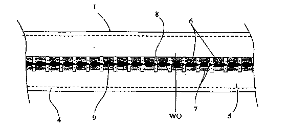
Figure ~: is an enl~rged cross-sect;Qn of ~he pos~c of Figure ~, and
Fi~ure 4: is an er~larged cross-section at the op~nin~ of the post of
Fi~ure a, and
Figures ~ 3 a ~ spective vi~w of a f~stener post and ~ire in
accordance ~il~h the present in~ntJon, a~d
Figure ~: i8 aI~ enl~rged cros~-~ection at 1~he openin~ of the post
re 2 sho~nng a fastener :~ced ~hereto, slnd
i~res 7 to 1~ lrate a me~hod by whic~ the po~t aE~gu~e 2 ~ be
fnrrne~ f~om a fla~ metal plate, and
~ure 1~. is a side ~new of a f~n~inE ~cc~,sso~ in accorda~ce wi~h
a fi~ her aspe~t of ~he pre~ ve~t;ol~, 7~a
Figure 1~ a cross-sech~ view of ~he ~e~n- ,~, of Pi~re 12.
1~ BEsT MODES FOR C~X~ H ~ I~VE~ ON
With respect ~ e ~aw~g8 a~d by way of e~ample a si~l3ple h~riz:r~n~l
wire fence compr~ses posts ~enerally inAiG~te~ by arro~ 1, iT~t~rmerli~te
n~: ge~er~y in~iss-~rl by arro~v 2~ and a plural~t~ of h~ri~:on~l fence
wires 3. The posts 1 are drive~ into ~he ground a~d the h~ n.~ span t he
~0 fe~ce wires from ~op to bottom. The fënce 8 ere~ed by dri~ing the
requirea nnmber of posts 1 i~to ~he ~rou~d securin~ wires ~ to ~he p~sts
u~ing ~taples or ~her means, tensioning the w~res alld then ~2cing 1~he
.r~.~ 2 ~ d~ired ~t~l ~als.

2 1 7~ ~6
wc~ ~10372 PCI'A~ZP4/~olO~
Wi~h respe~ to Fi~ures 2 to 6 of ~;he d~a~i~lgs a post 1 in ~Lccordan~e with
~he present in~enf;ion m~ have a s~ n~lly r~c~lire~r sectinn ~dy 4
hav~ng a fror~t face ~ wi~ ~n opening ge~er~lly in~ir~te~ by a~ow {i
therein.
~i ~pposîte f~ces of the body ~ m~y be of COI~lplim~.nt~ty equal or unequal
len~t;hs Each post may b~ pro~aded wi~h a cap (not shown~ which
p~otects 1~he ~ip of the post against imr~t~
I~efe~bly t~he body ~ is con~tructed in Tnet~lR a~ a~uresaid although o~
m:~}.~ may ~e s~ S3hl~
10 The c~g 6 is ~P~n~A by t~o illw~dl;y t'lrr-P~I ~ee edges 7 wh~ are
~e~ated such ~hat tips of th~ ~ee ed~e~ Ineet ~r nearly meet ~t 8 at
inter~ o~k~Q g beingpravided betwee~l. l~e fi~o~t fiace ~ thu~
~lese~ a ~eries of ~oc~;ets g to whi¢h f~steners or other ~tt~ nt
mP~ç c~ be sec~d.
1~ ~he ~e~ ~ ntl STAPL~LOE~ p~f~nt8 prev~ou~ lL~d to ~eS-'.rihe
how a staple c~n be drive~ ~Ilto ~ ch~n~ etween ~l~nges of post~ to
se~ure wire~ or o~ tt~r-~men~ to ~he po~s.
The orP,r~in~ 6 of l~he post of t~he prexq~ ..t;on Illso f~ilitates the
~tta~hm~nt of st~ples and other ~ccessorie$ in a $omewh~t ~
ao m:~nn~.r with the impor~nt ~c~l.t~o~ t~hat the ~ F 6 is not ~ channel
and the ar~an~e~ent of the present in~ on prevent~ longit~l~in~l
move~nt of the ~taple (mo~ement in a ~e~ical pl~ne when a fence is
e~e~ted). It is notea that the i~ner ~ost parts lO of the edgeg 7 ~re
b~ ;plly parallel to the ~ont face of t~he po~t, ~d that the ~;O
~5 ~re wider ~ ~e~y ~re deep.

- 21 74086
WO ~10;~2 PCrl~Z~4~0~108
The st~p~e ~ ;trated (~igures ~ and 8) has arms ~enera~ly indica:ted ~ y
arrow 11 which a~e ger~erally spear-sh~p~d havin~F ~ tip part 1~,
e~ ides 13 wh~ch lead tc a ~houlder 14 whe~e ~he arm ~rows to
be a pre~et~ nP~ widtll W l~ger ~n lhe wldt~ WO o 1~e soc~ets 9 in
the fro~t ~ce 6 of t~e post 1.
T~e post 1 can ~e forJned l~y roll f~rminE ~om a flat sheet of ms3t~ri~1 wit~
roller~ du~lly m~kinE~ eacI~ be~d in 1~he body o~ the post and fo~min~
t~he ~ ated fi~e edge~ 7. A~ ~e end ~ e ro1~ r - ...;..~ ~,ocess lhe ~losed
edges 7 are near conf~-~f. at ~te~ ls as ~i~c~ ed~
10 The r~ n~Q of metal ~llow~ 11 ~ a staple or o~her ~I,~e to be
drive~ ~nto 1~e ~a~-kP~ g by sn~ r ~.~ ana local~ed p~ng of t~e er~
0d~es, ~fflcient to allow Ihe ~nde~t par~ of t~e shn~lder 14 to p~ss
throu~h 1~he ~m ~ g whereupon ~hm~ .rs 14 lo~ate wit~ ed~s 8 o~ 1~he
post whi~ the ~h~erl~e of a ~olced re-o~ening of the op~r~ing; the
15 m~t~in,~ of ~he sho~lder ~nd ed~e se~e~ t;he ~rms 11 ~g~i~Bt
hdrawal. As ~1;P~ J t~e closed faces 8 ~l¢~,en~ 1~he
on t~e post. A~y ~ifil~ of arms 11 El1EO 1QCkS t~e armS fi1r~eT ~eC11r;n~
ag~a~st withdrawal.
The post ~escrihe~ is ~Q~ ed to haYe t3~e ~i~ific~nt ad~.r~tages of
~0 b~ ~ore robu~t ~han its pre~c-~co,s and whilst 7~;n~;ning E~ll of the
previou~ adva~tages~ the ~erl~ed face allow~ ~t~.ple~ snd att~r~m~ntQ to
be s~u~ely ~ixed a~d ~e po~t con~guration provides to to~ional and
other ~en~lin~ for~ whic;h m~y be imro~e~ on it.
~ en~iioned earlier was ~e f~t 1~t ~e posts ~.c~hed may ~e useful i~
~6 ~her applic~tinn~l for e~mr~ as studæ and nog~inF~ to support
walI/ceilin~ bo~ds q~ for pro~ding 4ro~lion a~d support fo~ dn~nE,
~O

21~8~
WC~ 9~1lQ37~ 10
suspended cP.ilin~s, pipes, ele~tricaI Nires.
With respe~t to Figures 7 to 11 of the drawings, ~e post of l;he present
illve~Lion can ~e ~o~ed by roll fo~ning app~ratus. The roll f~
appar~us is not sho~vn i~ filll in the d~ gs but ~u~arl~ and r~llers
are shown in broken ol~t.1inQ
Tn Fi~res 7 to 11, a met~l pl~ 16 is p~ogressive~y fo~med into the post
p~viously described.
~ Fi~ure 7 the met~l pla~e 16 is presexlted to s~lppo~ g roller 17.
Beyond roller 17, ~he edges 1~ of the plate 16 are ~ 8 the pl~te passes
10 between con~rlim~ y roller~ 19,20.
l~es~ond rolle~s 19,20, ~che pIate 1~; passes b~w~e~ cnn~r~ n~ rolIers
21,2~ wh~ re too~;hed e~ d ~e ed~es 18 ~re ~errated.
Be~ond roller~ ~1,22 ~re l~ he me~al plate i~s fQ ...e~ ~to lhe box-
shape ~n~ir~e~l by ~ller~ 24,25, ~ *J~Qd;~ lers (not shown) ~nd at
~!; ~e ni-~hinE poi~t r~ller 26 whî~h ha~ a t~in ce~tral ~L ~7 ~ent~alises
t~e me~ ect~tln
E~igures la ~d 13 of 1~he drawi~g~ illustra~e ~ h~nd post dr~ n~ tec~
b;y arrow 31 ~vhich i8 ~i~e~ ~0 cll~h;~n sh~ok ~ n~ tlse~ A .~t~n~rd
~ e$ ~ po~t tube 3~J cross-bars 33 ~a b~a~dlqs 34, these
2~ elements forming ~ :rîgid frame. The present i~lvf~rlL;on moAîfies this
arr~gement by mol-ntir~F a c~p 3~ tn t~e h~ p~ 34 and i ter~cl4i~g coil
sr~s ~6 between the llppe~ s-bar 3~ a~d 'Ghe ~p 35. A ~lid plug 37
ed in t~he end of post tube 3~!. ~ere is no ~nn~c~nn between ~h~ e~d
of the tu~e 32 ~ .n~ Le ~ap 3~ ~nd ~he hp~ e~ 34 are ~ to ~lide in top
ross~b~r 33. ~hen the tube 3~ is impacted ~n a po~t t~ ost e3~erts

~ 21 7408b
Wt~ 9S1~0372 lPCI'~4/00108
pressure o~ the pIug 37 and simult~neo~ly the 5p~iILgS ~re ~rten~P.l
cl~h;n~;n~e the blow and ~hen ~lm~st ~nst~ntaneously the end of ~he tube
3~ is Imr~.~te~ by ~he eap 3~ pro~ding suppleme~ary d~w~ forc~.
Aspects of the prefient invent ion have been ~escrihed by way of ~ le
5 only arLd i~ shoul~ ~e appreci~tec~ t mo~ f~n~ ~nd ~dditions ~ be
made thereto without depar~g ~om the scope th~reof ~ defined ~n the
appeI.~e~ cl:lim~

Representative Drawing
A single figure which represents the drawing illustrating the invention.
Administrative Status

2024-08-01:As part of the Next Generation Patents (NGP) transition, the Canadian Patents Database (CPD) now contains a more detailed Event History, which replicates the Event Log of our new back-office solution.

Please note that "Inactive:" events refers to events no longer in use in our new back-office solution.

For a clearer understanding of the status of the application/patent presented on this page, the site Disclaimer , as well as the definitions for Patent , Event History , Maintenance Fee  and Payment History  should be consulted.

Event History

Description Date
Inactive: IPC from MCD 2006-03-12
Application Not Reinstated by Deadline 2002-10-15
Time Limit for Reversal Expired 2002-10-15
Inactive: Abandon-RFE+Late fee unpaid-Correspondence sent 2001-10-15
Deemed Abandoned - Failure to Respond to Maintenance Fee Notice 2001-10-15
Application Published (Open to Public Inspection) 1995-04-20

Abandonment History

Abandonment Date Reason Reinstatement Date
2001-10-15

Maintenance Fee

The last payment was received on 2000-10-16

Note : If the full payment has not been received on or before the date indicated, a further fee may be required which may be one of the following

  • the reinstatement fee;
  • the late payment fee; or
  • additional fee to reverse deemed expiry.

Patent fees are adjusted on the 1st of January every year. The amounts above are the current amounts if received by December 31 of the current year.
Please refer to the CIPO Patent Fees web page to see all current fee amounts.

Fee History

Fee Type Anniversary Year Due Date Paid Date
MF (application, 3rd anniv.) - small 03 1997-10-14 1997-09-16
MF (application, 4th anniv.) - small 04 1998-10-14 1998-09-10
MF (application, 5th anniv.) - small 05 1999-10-14 1999-09-23
MF (application, 6th anniv.) - small 06 2000-10-16 2000-10-16
Owners on Record

Note: Records showing the ownership history in alphabetical order.

Current Owners on Record
MANUKAU FIFTY LIMITED
Past Owners on Record
KEVIN PATRICK JOYCE
RODNEY MITCHELL INNES
STUART MARTIN INNES
Past Owners that do not appear in the "Owners on Record" listing will appear in other documentation within the application.
Documents

To view selected files, please enter reCAPTCHA code :


To view images, click a link in the Document Description column. To download the documents, select one or more checkboxes in the first column and then click the "Download Selected in PDF format (Zip Archive)" or the "Download Selected as Single PDF" button.

List of published and non-published patent-specific documents on the CPD .

If you have any difficulty accessing content, you can call the Client Service Centre at 1-866-997-1936 or send them an e-mail at CIPO Client Service Centre.


Document
Description 
Date
(yyyy-mm-dd) 
Number of pages   Size of Image (KB) 
Representative drawing 1999-06-03 1 13
Abstract 1995-04-19 1 27
Claims 1995-04-19 3 87
Description 1995-04-19 8 309
Drawings 1995-04-19 7 186
Reminder - Request for Examination 2001-06-17 1 118
Courtesy - Abandonment Letter (Maintenance Fee) 2001-11-12 1 183
Courtesy - Abandonment Letter (Request for Examination) 2001-11-25 1 171
Fees 1996-10-10 1 83
International preliminary examination report 1996-04-11 31 987
Courtesy - Office Letter 1996-05-08 1 20
Courtesy - Office Letter 1996-11-17 1 24