Language selection

Search

Patent 2174268 Summary

Third-party information liability

Some of the information on this Web page has been provided by external sources. The Government of Canada is not responsible for the accuracy, reliability or currency of the information supplied by external sources. Users wishing to rely upon this information should consult directly with the source of the information. Content provided by external sources is not subject to official languages, privacy and accessibility requirements.

Claims and Abstract availability

Any discrepancies in the text and image of the Claims and Abstract are due to differing posting times. Text of the Claims and Abstract are posted:

  • At the time the application is open to public inspection;
  • At the time of issue of the patent (grant).
(12) Patent: (11) CA 2174268
(54) English Title: CONNECTOR MODULES
(54) French Title: MODULES DE CONNEXION
Status: Expired and beyond the Period of Reversal
Bibliographic Data
(51) International Patent Classification (IPC):
  • H01R 9/00 (2006.01)
  • H01R 9/24 (2006.01)
  • H04Q 1/14 (2006.01)
(72) Inventors :
  • BAGGETT, WILLIAM CALVIN (United States of America)
  • BAINES, ELLIOT ARTHUR JR. (United States of America)
  • FILUS, WAYNE SCOTT (United States of America)
  • GILLAND, DIANNE WOOD (United States of America)
  • KANE, ADAM STUART (United States of America)
  • SPAULDING, MARK GEORGE (United States of America)
  • STARACE, JEREMIA PATRICK (United States of America)
(73) Owners :
  • AT&T IPM CORP.
(71) Applicants :
(74) Agent: KIRBY EADES GALE BAKER
(74) Associate agent:
(45) Issued: 2001-08-14
(22) Filed Date: 1996-04-16
(41) Open to Public Inspection: 1996-11-18
Examination requested: 1996-04-16
Availability of licence: N/A
Dedicated to the Public: N/A
(25) Language of filing: English

Patent Cooperation Treaty (PCT): No

(30) Application Priority Data:
Application No. Country/Territory Date
442,866 (United States of America) 1995-05-17

Abstracts

English Abstract


Disclosed is a connector module which permits termination of cross-connect wireson one surface and cable wires on an opposite surface. The module exhibits a
generally "Z" shaped configuration which permits test access, jumper insertion, and
protector mounting on either surface.


Claims

Note: Claims are shown in the official language in which they were submitted.

- 4 -
Claims:
1. A connector module comprising:
an insulating housing having a top and bottom surface;
first and second rows of contacts mounted within the housing, each
contact including an end portion which is capable of providing electrical connection
to a corresponding wire and a stem portion, the contacts being mounted so that the
end portions of the first row extend through the top surface and the end portions of
the second row extend through the bottom surface, the end portions of the first and
second rows being laterally displaced, and the top and bottom surfaces includingslots adjacent to the corresponding rows for receiving therein leads which make
electrical contact with corresponding contacts.
2. A connector module according to claim 1 wherein each end portion
provides electrical connection by means of an insulation piercing slot.
3. A connector module according to claim 1 wherein the stem portions of
the contacts of the first row make electrical connection with the stem portions of
corresponding contacts of the second row and are aligned with corresponding slots in
the top and bottom surfaces in order to receive leads which are inserted in the slots.
4. A connector module according to claim 1 wherein the housing
includes insulating caps placed over the end portions of the first and second rows of
contacts, said caps including slits aligned with corresponding end portions to permit
wires to be inserted therein for making electrical connection with the end portions
and slots aligned with the stem portions to permit insertion of leads therein.
5. A connector module according to claim 1 further comprising a
protector component with at least one lead inserted into a slot on one of the top and
bottom surfaces.

Description

Note: Descriptions are shown in the official language in which they were submitted.


2~.7~~~~
-1-
Connector Modules
Background of the Invention
This invention relates to modules for electrically connecting sets of
wires.
In the telecommunications industry, connecting blocks comprising an
array of insulation displacement contacts are typically used in telephone
central
offices, building entrance terminals, and outside plant cabinets for
electrical
connection between cables and cross-connect wiring. One example of such a
connecting block is the standard 110 connector block. (See, for example, U.S.
Patent
No. 3,798,587.) Such connector blocks include rows of insulation displacement
contacts mounted within a plastic module. Each contact includes insulation
piercing
slots on both ends. One set of wires is placed within an alignment strip, and
the
contact module is placed over the wires in order to make contact therewith. A
second set of wires is inserted into the opposite end of the contacts to
complete the
electrical connection between the sets of wires. In some recent systems,
connector
modules include slots for mounting protectors which are electrically connected
to the
contacts. (See, for example, U.S. Patents 4,171,857 and 4,283,103.)
While the prior art connector blocks are adequate, the fact that all wiring
is generally done on the same surface has limited the density of wire
terminations.
Further, when protectors have been included in the block, they usually must be
removed in order to insert jumper wires or test probes, creating inconvenience
for
the user.
Summary of the Invention
The invention is a connector module which includes two rows of
contacts mounted within an insulating housing having a top and bottom surface.
Each contact includes an end portion which is capable of providing electrical
connection to a corresponding wire. The contacts are mounted so that the end
portions of the first row extend through the top surface and the end portions
of the
second row extend through the bottom surface. The end portions of the two rows
are
laterally displaced, and the top and bottom surfaces include slots adjacent to
the
corresponding rows for receiving leads therein which make electrical contact
with
corresponding contacts.

-2-
Brief Description of the Drawing
These and other features of the invention are delineated in detail in the
following description. In the drawing:
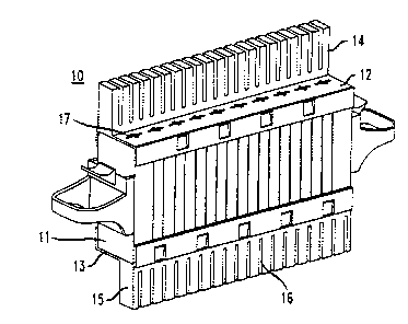
FIG 1 is a perspective view of a module in accordance with an
embodiment of the invention;
FIGS. 2-4 are cross-sectional views of a module in accordance with the
same embodiment; and
FIG. 5 is a perspective view of the module of FIG. 1 with an additional
component illustrated.
It will be appreciated that, for purposes of illustration, these figures are
not necessarily drawn to scale.
Detailed Description
Illustrated in FIG. 1 is a module, 10, which can be inserted into a frame
(not shown) along with other similar modules to form a connecting block. The
module includes a housing which is made of insulating material such as
plastic. The
housing includes an essentially rectangular body portion, 1 l, which is
covered by
caps, 14 and 15, respectively. The caps can be made of the same material as
the
housing and define an upper and lower surface, 12 and 13, respectively, for
the
housing. Each cap includes a series of slits, e.g., 16, which permit insertion
of a wire
(e.g., 61 of FIG. 4 ) therein as discussed below. Each cap also includes a
series of
slots, e.g., 17 and 18 of FIG. 2, in the top and bottom surfaces, 12 and 13,
of the
housing, which slots permit insertion of leads, e.g., 19 of FIG. 5, which may
be
electrically coupled to a cartridge protector, 20 of FIG. 5, a single
protector , 21 of
FIG. 3, a test probe, 22 of FIG. 4, or possibly other components.
As illustrated in FIGS. 2-4, mounted within the housing is a first row of
contacts, e.g., 30, and a second row of contacts, e.g., 31. Each contact, 30
and 31,
includes an end portion, 32 and 33, respectively, which is capable of
providing
electrical connection to a wire, 60 and 61, respectively. In this embodiment,
the end
portions each comprise a slot, 34 and 35, which pierces the insulation
surrounding
the wire to establish electrical contact. The contacts are mounted so that the
end
portions of the first row of contacts, e.g., 30, protrude through the top
surface, 12, of
the housing, while the end portions of the second row of contacts, e.g., 31,
protrude
through the bottom surface, 13, of the housing. The end portions, e.g., 33,
are also
aligned with corresponding slits, e.g., 16 of FIG. 1, in the caps, e.g., 15 of
FIG. 1, so
that wires may be inserted through the caps for electrical connection by the
contacts.

CA 02174268 2000-06-27
-3-
The remainder of the contacts, 30 and 31, also known as the stem
portions, extend in the body portion, 11, so that one contact, 30, from the
first row
makes mechanical and electrical contact with another contact, 31, from the
second
row. In this embodiment, the two contacts make mechanical and electrical
contact at
two points, 38 and 39, as more fully discussed in U.S. Patent No. 5,549,489
issued on
August 27, 1996.
It will be noted that the end portions of the first and second rows of
contacts, e.g., 30 and 31, are laterally separated by a distance, L, with the
slots, e.g.,
17 and 18, disposed in the lateral space. The contact points, 38 and 39, are
aligned
with their respective slots, 17 and 18, so that, in the example illustrated in
FIGS. 3
and 4, a lead, 40, of a protector unit, 21, may be inserted in the slot, 18,
to make
contact with the stems, and the lead, 41, of a test cord, 22, may be inserted
in the slot,
17, to also make contact with the stems.
It will be appreciated that there are several advantages to the module
disclosed herein. For example, wires, 61, from the cable can be connected to
the
contacts, e.g., 31, of the second row at the bottom of the module, and cross-
connect
wires, 60, can be connected to the contacts, e.g., 30, of the first row at the
top of the
module. By utilizing two surfaces of the module, the density of terminations
is
increased. Further, the user has the opinion of inserting protector units at
the bottom
surface as illustrated in FIGS. 3 and 4, or at the top surface as illustrated
in FIG. 5,
where a protector cartridge, 20, including a plurality of gas tube protectors
is
illustrated. In either case, the protectors can remain in place when it is
desired to
insert a test probe, 22, or a jumper cable (not shown) in the opposite surface
of the
module. Also, with the protectors on the bottom surface, there is plenty of
room to
connect the cross-connect wires at the top surface without the necessity of
removing
the protectors.
Various modifications of the embodiment described herein will
become apparent to the skilled artisan. For example, the body portion, 11,
need not
be open at the top and bottom and covered by the caps as shown, but can have
its
own top and bottom surface with either no cap or with a cap which covers only
the
end portions of the contacts. The invention claimed is:

Representative Drawing
A single figure which represents the drawing illustrating the invention.
Administrative Status

2024-08-01:As part of the Next Generation Patents (NGP) transition, the Canadian Patents Database (CPD) now contains a more detailed Event History, which replicates the Event Log of our new back-office solution.

Please note that "Inactive:" events refers to events no longer in use in our new back-office solution.

For a clearer understanding of the status of the application/patent presented on this page, the site Disclaimer , as well as the definitions for Patent , Event History , Maintenance Fee  and Payment History  should be consulted.

Event History

Description Date
Inactive: IPC expired 2018-01-01
Time Limit for Reversal Expired 2012-04-16
Letter Sent 2011-04-18
Inactive: IPC from MCD 2006-03-12
Grant by Issuance 2001-08-14
Inactive: Cover page published 2001-08-13
Inactive: Final fee received 2001-05-08
Pre-grant 2001-05-08
Letter Sent 2000-11-21
Notice of Allowance is Issued 2000-11-21
Inactive: Approved for allowance (AFA) 2000-11-07
Amendment Received - Voluntary Amendment 2000-06-27
Inactive: S.30(2) Rules - Examiner requisition 2000-01-04
Inactive: Status info is complete as of Log entry date 1998-04-20
Inactive: Application prosecuted on TS as of Log entry date 1998-04-20
Application Published (Open to Public Inspection) 1996-11-18
Request for Examination Requirements Determined Compliant 1996-04-16
All Requirements for Examination Determined Compliant 1996-04-16

Abandonment History

There is no abandonment history.

Maintenance Fee

The last payment was received on 2001-03-21

Note : If the full payment has not been received on or before the date indicated, a further fee may be required which may be one of the following

  • the reinstatement fee;
  • the late payment fee; or
  • additional fee to reverse deemed expiry.

Please refer to the CIPO Patent Fees web page to see all current fee amounts.

Owners on Record

Note: Records showing the ownership history in alphabetical order.

Current Owners on Record
AT&T IPM CORP.
Past Owners on Record
ADAM STUART KANE
DIANNE WOOD GILLAND
ELLIOT ARTHUR JR. BAINES
JEREMIA PATRICK STARACE
MARK GEORGE SPAULDING
WAYNE SCOTT FILUS
WILLIAM CALVIN BAGGETT
Past Owners that do not appear in the "Owners on Record" listing will appear in other documentation within the application.
Documents

To view selected files, please enter reCAPTCHA code :


To view images, click a link in the Document Description column. To download the documents, select one or more checkboxes in the first column and then click the "Download Selected in PDF format (Zip Archive)" or the "Download Selected as Single PDF" button.

List of published and non-published patent-specific documents on the CPD .

If you have any difficulty accessing content, you can call the Client Service Centre at 1-866-997-1936 or send them an e-mail at CIPO Client Service Centre.


Document
Description 
Date
(yyyy-mm-dd) 
Number of pages   Size of Image (KB) 
Cover Page 1996-07-18 1 19
Description 1996-07-18 3 161
Claims 1996-07-18 1 41
Abstract 1996-07-18 1 9
Drawings 1996-07-18 2 59
Description 2000-06-27 3 161
Cover Page 2001-08-07 1 42
Representative drawing 2001-08-07 1 16
Representative drawing 1998-08-19 1 18
Reminder of maintenance fee due 1997-12-17 1 111
Commissioner's Notice - Application Found Allowable 2000-11-21 1 165
Maintenance Fee Notice 2011-05-30 1 171
Correspondence 2001-05-08 1 36