Language selection

Search

Patent 2174381 Summary

Third-party information liability

Some of the information on this Web page has been provided by external sources. The Government of Canada is not responsible for the accuracy, reliability or currency of the information supplied by external sources. Users wishing to rely upon this information should consult directly with the source of the information. Content provided by external sources is not subject to official languages, privacy and accessibility requirements.

Claims and Abstract availability

Any discrepancies in the text and image of the Claims and Abstract are due to differing posting times. Text of the Claims and Abstract are posted:

  • At the time the application is open to public inspection;
  • At the time of issue of the patent (grant).
(12) Patent: (11) CA 2174381
(54) English Title: A SNARE STRAINER FOR A DRUM
(54) French Title: CREPINE POUR BARIL
Status: Expired and beyond the Period of Reversal
Bibliographic Data
(51) International Patent Classification (IPC):
(72) Inventors :
  • NICKEL, GREGORY L. (Canada)
(73) Owners :
  • GREGORY L. NICKEL
(71) Applicants :
  • GREGORY L. NICKEL (Canada)
(74) Agent: RICHES, MCKENZIE & HERBERT LLP
(74) Associate agent:
(45) Issued: 2000-08-01
(22) Filed Date: 1996-04-17
(41) Open to Public Inspection: 1996-10-20
Examination requested: 1996-09-13
Availability of licence: N/A
Dedicated to the Public: N/A
(25) Language of filing: English

Patent Cooperation Treaty (PCT): No

(30) Application Priority Data:
Application No. Country/Territory Date
08/424,805 (United States of America) 1995-04-19

Abstracts

English Abstract


A snare strainer for a drum. The snare strainer
includes a cylindrical tube which is mounted on the shell of
a drum. A piston is installed in the cylindrical tube for
slidable movement between a first position in which the
snares are positioned against the head of the drum and a
second position in which the snares are moved away from the
head of the drum. The snare strainer includes a handle
pivotally mounted on the cylindrical tube which is connected
to a cross member engaging the piston by a link. The link
is pivotally connected at one end to the cross member and at
its opposite end to a pivotal connection of said handle.
The pivotal connections are positioned so that rotation of
the handle to move the piston between the first and second
positions of the piston moves the pivotal connection of the
handle of the link and the pivotal connection of the link of
the cross member through over center positions. The
cylindrical tube is formed of a glass reinforced polycar-
bonate and the piston is formed of a nylon 66.


Claims

Note: Claims are shown in the official language in which they were submitted.

THE EMBODIMENTS OF THE INVENTION IN WHICH AN EXCLUSIVE
PROPERTY OR PRIVILEGE IS CLAIMED ARE DEFINED AS FOLLOWS:
1. A snare strainer for a snare drum having snares
and a shell, said snare strainer including:
a cylindrical tube,
means to mount said cylindrical tube to the shell of
the drum,
a piston installed in said cylindrical tube for
slidable movement between a first position and a second
position,
a snare tensioning rod affixed to said piston and said
snares to locate said snares against said drum when said
piston is in said first position and to locate said snares
away from said drum when said piston is in said second
position,
a quick release mechanism mounted on said cylindrical
tube and connected to said piston for moving said piston
between said first and second positions,
said quick release mechanism including a handle
pivotally mounted on said cylindrical tube, a cross member
engaging said piston, and an elongated closed loop link
pivotally connected at one end to said cross member and at
an opposite end to said handle so that the rotation of said
handle will rotate said pivotal connections of said link to
an over center position during movement of said piston
between said first and second positions.
2. The snare strainer of claim 1 including a knob
installed in said cylindrical tube in contact with said
piston, and means connecting said knob to said snare
tensioning rod to slide said knob and said snare tensioning
rod relative to each other upon rotation of said knob.
3. The snare strainer of claim 1 in which said
cylindrical tube is formed with a relatively thick wall and
said piston is formed with a relatively large diameter
providing large bearing surfaces to accurately guide said
snare strainer during actuation.

4. The snare strainer of claim 3 in which said
cylindrical tube is formed of a glass reinforced
polycarbonate and said piston is formed of a nylon which is
compatible with said glass reinforced polycarbonate.

Description

Note: Descriptions are shown in the official language in which they were submitted.


21 74381
A SNARE STRAINER FOR A DRUM
Backqround and Summary of the Invention
This invention is directed to a snare strainer having
many of its moving and guiding components formed,
dimensioned and arranged to eliminate the undesirable
features of conventional snare strainer mechanisms such as
internal rattling, noise during release of tensioning or
"throw-off" of the snares, incompatibility with drums of
varying sizes and high cost of production.
An object of this invention is a snare strainer whose
design and not necessarily the material of its construction
provides the required structural and mechanical integrity.
Another object of this invention is a snare strainer
which firmly guides the snares during both the application
and release of tension on the snares.
Still another object of this invention is a snare
strainer having operating component parts formed with large
bearing surfaces to accurately guide the strainer during
actuation.
An additional object of this invention is a snare
strainer having a self-locking, fine tuning mechanism for
tensioning the snares.
Yet another object of this invention is a snare
strainer which is noiseless during both the application and
the release of tension on the snares.
A further object of this invention is a snare strainer
which is guided during the application of tension to and
release of tension on the snares by movement of a relatively
large diameter piston in a relatively thick walled tube.
Yet still another object of this invention is a snare
strainer which is operated by a link in an over center lever
mechanism to lock the strainer in its snare tensioning
position.
A still further object of this invention is a snare
strainer some of whose component parts are constructed of
glass reinforced polycarbonate and others of nylon.

21 74381
Other objects of the invention may be found in the
following specification, claims and drawings.
Brief Description of the Drawings
The invention is illustrated more or less diagrammati-
cally in the following drawings wherein:
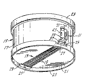
Fig. 1 is a bottom perspective view of a snare drum on
which is mounted a snare strainer of this invention;
Fig. 2 is an enlarged, partial, broken, cross sectional
view of a shell of a drum on which is mounted the snare
strainer of this invention;
Fig. 3 is a side elevational view of the snare strainer
of this invention in its snare tension applying position;
Fig. 4 is a view of the snare strainer of ~ig. 3 shown
in its snare tension released position;
Fig. 5 is a bottom plan view of the snare strainer of
Fig. 3;
Fig. 6 is a view taken along line 6-6 of Fig. 3; and
Fig. 7 is a cross sectional view taken along line 7-7
of Fig. 6.
Description of the Preferred Embodiment
Fig. 1 of the drawings shows the snare strainer 11 of
this invention attached to a snare unit 13 mounted on a drum
15. As is conventional, the drum 15 includes a shell 17
with the wires or snares 19 of the snare unit 13 positioned
against the bottom drum head 21 of the drum. The drum heads
are held in position against the shell 17 by rims 23.
The opposite ends of the snare wires 1~ are held by a
stationary snare anchor 25 and a shiftable snare anchor 27
which extend through notches 29 formed in the lower rim 23.
The stationary snare anchor 25 is held by a cross member 31
to a bracket 33 which fastened to the shell 17 of the drum
by fasteners 35. The shiftable snare anchor 27 connects to
a T-shaped snare clamp 37 which is formed integrally with a
snare tensioning rod 39 of rectangular cross section.
The snare strainer 11 includes a cylindrical tube 41
formed of a polycarbonate reinforced with 1-5% glass fibers-
which is sold under the trademark LEXAN 41 by the General

~ 2 1 7438 1
Electric company . The cylindrical tube 41 has an integral
L-shaped bracket 43 by which it is mounted on the shell 17
of the drum by threaded fasteners 45 (Fig. 2). A
cylindrical knob 47 telescopes into the cylindrical tube 41.
The knob includes an integral head 49 of greater diameter.
-A rubber washer 51 encircles the knob at the base of the
head and functions as a sound deadening cushion.
A piston 53 is installed in the cylindrical tube 41 in
engagement with the knob 47 as can be best seen in Fig. 7.
The piston may be made of a plastic, preferably a nylon 66
sold under the trademark ZYTEL 100 by E. I. DuPont de
Nemours ~ Co. As can also be seen in Fig. 7 of the
drawings, a metal rod 55 is positioned in a bore 57 in the
knob 47 and is held in position by a set screw 59. The rod
extends out of the knob 47, through a bore 60 and into an
enlarged bore 61, both in the piston. The rod 55 is
provided with an enlarged head 63 int~rme~;~te its ends.
The lower portion of the rod 55 is threaded at 65 to mesh
with inside threads 67 of the snare tensioning rod 39.
An operating handle 71 for applying tension to and
releasing tension from the snare bed 13 is pivotally mounted
by a pivot pin 73 to a bracket 75 formed integrally with the
cylindrical tube 41. Also carried on the handle 71 is a
pivot pin 77 which is a part of a link assembly 81 attached
to the handle. The link assembly 81 is preferably of the
type used as a repair link for motorcycles and which is sold
under the tra~m~rk "MASTERLINK". The link assembly 81
includes two spacer links 81a, one positioned on each side
of the handle and a locking clip link 81b which holds the
link assembly together. A pivot pin 83 fits in the opposite
end of the link assembly and it is pivotally connected to
the head 85 of a cross rod 87 which extends through a cross
passage 89 in the cylindrical tube 41 and a cross passage 90
in the piston 53. The pivot pins 77 and 83 are positioned
closer to the cylindrical tube 41 than is the pivot pin 73
when the handle 71 is moved to its tension applying position
shown in Figs. 3 and 7 of the drawings. In this position of

~ 21 74381
the handle 71, the pivot pin 77 which connects the handle
and the link assembly 81 is closest to the cylindrical tube
41 snd thus is in an over center position relative to both
the pivot pin 73 and the pivot pin 83. The over centering
of the pivot pins 77 and 83 in the tensioning applying
position of the operating handle 71 prevents accidental
release of the handle.
The cross rod 87 has a transverse passage 91 which
receives the rod 55. A set screw 92 of nylon fastens the
cross rod 87 to the rod 55 by engaging the threads of the
rod. The cross rod 87 locks the piston 53 in position
relative to the rod 55. As best can be seen in Figs. 2 and
7 of the drawings, the cross passage 89 in the cylindrical
tube 41 is elongated and permits the cross rod 87 to be
moved along the length of the cross passage 89 in the
cylindrical tube 41 upon rotation of the handle 71.
When the snare wires 19 are in contact with a drum head
21 as shown in Figs. 1 and 2 of the drawings, the operating
handle 71 is in its vertical position, as additionally shown
in Figs. 3, 6 and 7 of the drawings, with the cross rod 87
at the top of the elongated cross passage 89 of the
cylindrical tube 41. With the handle in this upward
position, the pivot pin 77 is located in an over center
position relative to the pivot pins 73 and 83 of the
operating mechanism. When the handle 71 is rotated in a
clockwise direction as viewed in Figs. 3, 4 and 7 of the
drawings to move the snares 19 of the snare bed to their
tension released position, the pivot pin 77 of the handle 71
is moved through an over center position relative to the
pivot pin 73 and the pivot pin 83 to move the cross rod 87
downwardly along the length of the cross passage 89. The
piston 53 is forced downwardly by the cross rod 87 to move
the snare tensioning rod 39, the snare anchor 27 and the
snares 19 in a downwardly direction as viewed in Figs. 1 and
2 of the drawings. When the handle reaches its lowered
position as shown in Fig. 4 of the drawings, the washer 51

~ 21 7~381
prevents the head 49 of the knob 47 from engaging the top of
the cylindrical tube 41 and m~ki ng a sound.
The tension on the snare wires 19 of the snare bed 13
can be ad~usted by rotating the knob 47 relative to the
cylindrical tube 41. Because of the tight fitting
relationship between the set screw 92 and the threaded rod
55, the tensioning rod 39 and the knob will lock in position
after tensioning adjustments. Rotation of the knob 47 will
rotate the threads at the end 65 of the rod 55 relative to
the inside threads 67 of the snare tensioning rod 39 to
accurately move the snare tensioning rod and snare anchor 27
and, thus, adjust the tension of the snares 19 on the snare
bed 13.
The design of the sliding piston 53 in the cylindrical
tube 41 provides relatively large bearing surfaces for the
moving parts of the snare strainer 11. These large bearing
surfaces permit the snare strainer to be constructed for the
most part of plastic without sacrificing its structural
integrity. The use of plastic provides the advantages
heretofore described as well as economies of manufacture.

Representative Drawing
A single figure which represents the drawing illustrating the invention.
Administrative Status

2024-08-01:As part of the Next Generation Patents (NGP) transition, the Canadian Patents Database (CPD) now contains a more detailed Event History, which replicates the Event Log of our new back-office solution.

Please note that "Inactive:" events refers to events no longer in use in our new back-office solution.

For a clearer understanding of the status of the application/patent presented on this page, the site Disclaimer , as well as the definitions for Patent , Event History , Maintenance Fee  and Payment History  should be consulted.

Event History

Description Date
Inactive: IPC expired 2020-01-01
Inactive: Adhoc Request Documented 2010-03-10
Time Limit for Reversal Expired 2002-04-17
Letter Sent 2001-04-17
Grant by Issuance 2000-08-01
Inactive: Cover page published 2000-07-31
Letter Sent 2000-05-12
Final Fee Paid and Application Reinstated 2000-05-04
Inactive: Final fee received 2000-04-27
Pre-grant 2000-04-27
Deemed Abandoned - Failure to Respond to Maintenance Fee Notice 2000-04-17
Notice of Allowance is Issued 1999-11-01
Letter Sent 1999-11-01
Notice of Allowance is Issued 1999-11-01
Inactive: Approved for allowance (AFA) 1999-10-06
Inactive: Status info is complete as of Log entry date 1998-01-05
Inactive: Application prosecuted on TS as of Log entry date 1998-01-05
Application Published (Open to Public Inspection) 1996-10-20
All Requirements for Examination Determined Compliant 1996-09-13
Request for Examination Requirements Determined Compliant 1996-09-13

Abandonment History

Abandonment Date Reason Reinstatement Date
2000-04-17

Maintenance Fee

The last payment was received on 2000-05-04

Note : If the full payment has not been received on or before the date indicated, a further fee may be required which may be one of the following

  • the reinstatement fee;
  • the late payment fee; or
  • additional fee to reverse deemed expiry.

Patent fees are adjusted on the 1st of January every year. The amounts above are the current amounts if received by December 31 of the current year.
Please refer to the CIPO Patent Fees web page to see all current fee amounts.

Fee History

Fee Type Anniversary Year Due Date Paid Date
Request for examination - small 1996-09-13
MF (application, 2nd anniv.) - small 02 1998-04-17 1998-03-06
MF (application, 3rd anniv.) - small 03 1999-04-19 1999-03-26
Final fee - small 2000-04-27
Reinstatement 2000-05-04
MF (application, 4th anniv.) - small 04 2000-04-17 2000-05-04
Owners on Record

Note: Records showing the ownership history in alphabetical order.

Current Owners on Record
GREGORY L. NICKEL
Past Owners on Record
None
Past Owners that do not appear in the "Owners on Record" listing will appear in other documentation within the application.
Documents

To view selected files, please enter reCAPTCHA code :


To view images, click a link in the Document Description column. To download the documents, select one or more checkboxes in the first column and then click the "Download Selected in PDF format (Zip Archive)" or the "Download Selected as Single PDF" button.

List of published and non-published patent-specific documents on the CPD .

If you have any difficulty accessing content, you can call the Client Service Centre at 1-866-997-1936 or send them an e-mail at CIPO Client Service Centre.


Document
Description 
Date
(yyyy-mm-dd) 
Number of pages   Size of Image (KB) 
Description 1996-07-23 5 241
Abstract 1996-07-23 1 30
Claims 1996-07-23 2 56
Drawings 1996-07-23 2 73
Representative drawing 1998-06-01 1 11
Representative drawing 2000-07-11 1 15
Reminder of maintenance fee due 1997-12-17 1 111
Commissioner's Notice - Application Found Allowable 1999-10-31 1 164
Courtesy - Abandonment Letter (Maintenance Fee) 2000-05-11 1 183
Notice of Reinstatement 2000-05-11 1 171
Maintenance Fee Notice 2001-05-14 1 178
Correspondence 2000-04-26 1 39
Fees 2000-05-03 1 43
Fees 1998-03-05 1 47
Fees 1999-03-25 1 44