Language selection

Search

Patent 2174465 Summary

Third-party information liability

Some of the information on this Web page has been provided by external sources. The Government of Canada is not responsible for the accuracy, reliability or currency of the information supplied by external sources. Users wishing to rely upon this information should consult directly with the source of the information. Content provided by external sources is not subject to official languages, privacy and accessibility requirements.

Claims and Abstract availability

Any discrepancies in the text and image of the Claims and Abstract are due to differing posting times. Text of the Claims and Abstract are posted:

  • At the time the application is open to public inspection;
  • At the time of issue of the patent (grant).
(12) Patent Application: (11) CA 2174465
(54) English Title: NOISE REDUCTION FOR SUCTION ROLL OF A PAPER MACHINE
(54) French Title: METHODE POUR LA REDUCTION DU BRUIT PRODUIT PAR LE ROULEAU ASPIRANT D'UNE MACHINE A FABRIQUER LE PAPIER
Status: Deemed Abandoned and Beyond the Period of Reinstatement - Pending Response to Notice of Disregarded Communication
Bibliographic Data
(51) International Patent Classification (IPC):
  • D21F 5/14 (2006.01)
  • D21F 3/10 (2006.01)
(72) Inventors :
  • HIRSCH, ADALBERT (Germany)
  • PRINZING, HANS (Germany)
(73) Owners :
  • VOITH SULZER PAPIERMASCHINEN GMBH
(71) Applicants :
  • VOITH SULZER PAPIERMASCHINEN GMBH (Germany)
(74) Agent: MARKS & CLERK
(74) Associate agent:
(45) Issued:
(22) Filed Date: 1996-04-18
(41) Open to Public Inspection: 1996-10-20
Availability of licence: N/A
Dedicated to the Public: N/A
(25) Language of filing: English

Patent Cooperation Treaty (PCT): No

(30) Application Priority Data:
Application No. Country/Territory Date
295 06 620.2 (Germany) 1995-04-19

Abstracts

English Abstract


A suction roll for a paper machine or the like
including a perforated annular roll shell which is
rotatable. A stationary suction box inside the roll
shell with respect to which the shell rotates. The
suction box is defined between two circumferentially
spaced sealing ledges at the roll shell. A noise
dampening chamber on the downstream side of the suction
box defined by a further sealing ledge at the roll shell.
A conduit communicating to the noise damping chamber to
allow increased pressure in the chamber which reduces
noise. At least one of a snifter valve, a suction
blower, an air pump and a water pump communicating to the
conduit for selectively adjusting the pressure in the
noise damping chamber for damping roll noise.


Claims

Note: Claims are shown in the official language in which they were submitted.

-7-
The embodiments of the invention in which an exclusive
property or privilege is claimed are defined as follows:
1. A suction roll comprising:
a roll shell which is perforated, the roll
shell being rotatable around an axis;
a stationary suction box disposed within
the roll shell and the roll shell being rotatable with
respect to the suction box;
the suction box including
circumferentially spaced apart sealing ledges, each ledge
contacting the interior of the roll shell at a respective
circumferentially spaced apart location around the roll
shell and defining a suction zone in the suction box
between the ledges at the roll shell;
a first one of the ledges being at the
circumferential discharge side of the suction box past
which the roll shell rotates as it leaves the suction
zone;
an additional sealing ledge spaced from
the first ledge circumferentially around the roll shell
and also contacting the interior of the roll shell; means
inside the roll shell defining a closed noise damping
chamber sealed at the roll shell between the first ledge
and the additional ledge, whereby the noise damping
chamber follows the suction zone downstream in the
rotation path of the roll shell;
a connection from the noise damping
chamber to means selectively allowing [an increase or a
decrease in pressure in the] noise damping chamber, for
causing reduction in the noise which is generated by the
suction roll.
2. The suction roll of claim 1, wherein the
suction roll includes an arcuate portion of its

-8-
circumference on which a web to which suction is to be
applied is wrapped; the suction box and the noise damping
chamber being within the arcuate circumferential region
wrapped by the web.
3. The suction roll of claim 2, wherein the
means allowing [an increase or a decrease of pressure in]
the noise damping chamber comprises means communicating
with the area surrounding the suction roll.
4. The suction roll of claim 2, wherein the
means allowing [an increase or a decrease of pressure in]
the chamber comprises at least one connecting conduit
communicating out of the suction chamber.
5. The suction roll of claim 4, further
comprising a controllable snifter valve connected into
the connecting conduit and also communicating to the
surroundings of the suction roll.
6. The suction roll of claim 4, further
comprising a suction blower connected into the connecting
conduit and means connected with the suction blower for
controlling the blowing by the suction blower into the
connecting conduit.
7. The suction roll of claim 4, further
comprising an air pump connected into the connecting
conduit.
8. The suction roll of claim 4, further
comprising a water pump connected into the connecting

-9-
conduit decreasing pressure into the noise damping
chamber.
9. The suction roll of claim 4, further
comprising all of a snifter valve connected to the
connecting conduit and communicating to the surroundings
of the suction roll, a suction blower connected to the
connecting conduit, an air pump connected to the
connecting conduit, and a water pump connected to the
connecting conduit; and means at each of the snifter
valve, the suction blower, the air pump and the water
pump for selectively connecting each to the connecting
conduit for adjusting pressure in the connecting conduit
and the noise damping chamber.
10. The suction roll of claim 4, further
comprising a pressure measuring instrument connected to
the noise damping chamber.
11. The suction roll of claim 2, wherein the
suction box is shaped to have a relatively larger volume
and the noise damping chamber is shaped to have a
relatively smaller volume, and between the first and
additional ledges, the noise damping chamber occupies a
smaller arcuate length along the perforated shell than
does the suction zone between the two ledges thereof.
12. The suction roll of claim 2, further
comprising means for delivering suction to the suction
box.
13. The suction roll of claim 2, wherein the
perforations in the roll shell are so sized and placed

- 10 -
that upon rotation of the roll shell, the reduced
pressure is carried in the perforations from the suction
box to the chamber.
14. The suction roll of claim [1], wherein the
perforations in the roll shell are so sized and placed
that upon rotation of the roll shell, the reduced
pressure is carried in the perforations from the suction
box to the chamber.

Description

Note: Descriptions are shown in the official language in which they were submitted.


21744fi5
~ P/563-30
NOISE REDUCTION FOR SUCTION ROLL OF A PAPER MACHINE
BACKGROUND OF THE I~v~llON
The present invention relates to a suction roll
having an internal suction box with improved noise
damping. Suction rolls are used preferably in paper
manufacturing machines, particularly to assist in
removing water from the wet web of paper or board. One
problem which has been encountered for decades is the
disagreeable production of noise by such suction rolls.
Numerous measures for reducing the noise produced by
suction rolls have been described. See, for instance,
the TAPPI journal, December 1956, Vol. 39, No. 12, pages
851 to 857.
Furthermore, U.S. Patent 2,857,823 discloses
placing a sound damping chamber along the discharge or
circumferential outlet side of the stationary suction
box. The inside of the sound damping chamber is
connected by relatively fine openings with the inner
surface of the shell of the suction roll and with the
rest of the inside of the suction roll.
Known measures for reducing noise generated by
a suction roll may be effective to a greater or lesser
extent with machine operating speeds that are not too
high. However, in modern paper manufacturing machines,
with operating speeds of between 1000 and 2000 m/min,
sound reduction techniques are insufficient. Traditional
devices for reducing noise do not prevent production of a
disagreeable noise by suction rolls operating at higher
speeds.
SPI~C\148678

2174465
-
- 2
SUMMARY OF THE INVENTION
The object of the present invention is to
develop a known suction roll with a clearly perceptible
reduction in noise, even when operating at extremely high
speeds, as compared with known rolls.
Another object is to provide a noise damping
chamber in a suction roll which uses a pressure different
than in the adjacent suction box and selected to reduce
noise.
This object is achieved by providing a sealed
damping chamber at the interior of the suction roll shell
and past the downstream side of the suction box in the
roll. The chamber is connectable to the surrounding area
of or outside the suction roll which is at a higher
pressure. For example, either a pressure supply or a
suction source is connected to the chamber through a
valve. The pressure supply or suction source connection
may be through a snifter valve to the environment or may
be to an air or water pump, or a blower, or the like.
Other objects and features of the invention are
apparent from the following description of the invention
shown in the accompanying drawings.
BRIEF DESCRIPTION OF THE DRAWINGS
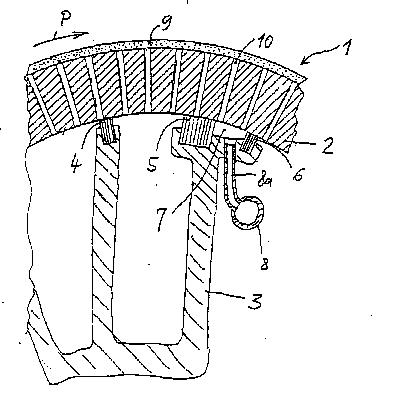
Fig. 1 is a cross-section through a fragment
of a suction roll; and
Fig. 2 is a schematic diagram of the conduits
which are connected to the noise damping chamber of the
suction roll.
DETAILED DESCRIPTION OF THE INVENTION
The invention may be used with an
otherwise conventional suction roll, e.g. as in British
SPEC\148678

217~65
-
- 3 -
Patent 733,242. Fig. 1 shows part of a suction roll 1,
including a part of a revolving annular roll shell 2
which has radial perforations 10 passing through the
shell. The direction of roll rotation is indicated by an
arrow P. A paper web travels together with a wire or
felt belt, both diagrammatically shown at 9, over the
periphery of the rotating suction roll 1.
There is a stationary sealed chamber suction
box 3 within the rotating suction roll shell 2. The
reduced pressure in the suction box communicates with the
inner surface of the roll shell 2 between the sealing
ledges 4 and 5 spaced apart circumferentially around the
shell. These sealing ledges define a suction zone of the
suction box between them in the interior of the rotating
roll shell. The circumferential length of the suction
box between the ledges 4 and 5 is selected for the
particular application for the roll, as in a suction
press roll or a dryer section roll, etc. A further
suction zone can be present in front of or upstream of
the suction zone with respect to the direction of roll
rotation. As is conventional, a conduit at the end of
the roll brings vacuum into the suction box.
There is a noise damping chamber 7 behind or
downstream of the suction zone defined by the sealing
ledges 4 and 5 in the direction of rotation. The chamber
7 also communicates with the interior surface of the
rotating roll shell. The chamber 7 is defined by the
discharge side sealing ledge 5 of the suction box and by
an additional sealing ledge 6 which is circumferentially
spaced downstream from the ledge 5. The circumferential
length of the suction zone at the roll shell between the
ledges 4 and 5 is shown as longer than the
circumferential length at the roll shell of the noise
SPEC\148678

2I7~65
- 4 -
damping chamber between the ledges 5 and 6, although this
is not required. Also, the volume of the chamber 7 is
smaller, although this is not required. Reduced pressure
in the suction box reduces the pressure in the
S perforations 10 beneath the felt belt 9. The rotating
shell 2 "transports" the reduced pressure from the
suction box to the chamber 7, which thereby reduces the
pressure in the chamber 7.
Fig. 2 indicates the contour of the suction
roll 1 diagrammatically with dashed lines and the contour
of the noise damping chamber 7 with solid lines. A
connecting conduit 8 extends substantially through the
entire length of, i.e., across the interior of the
suction roll. The conduit is connected by several
transverse conduits 8a spaced at intervals along the
length of the roll to the noise damping chamber 7. The
connecting conduit 8 ends at some means by which the
pressure within the chamber 7 can be selectively
increased or decreased for achieving noise reduction. At
a particular time or in a particular application, the
pressure increase or decrease will achieve the noise
reduction.
For instance, the conduit 8 may end at a
controllable snifter valve 11. The snifter valve 11 can
be opened to a greater or lesser extent when a vacuum is
present in the noise damping chamber such that the noise
caused by the rotation of the suction roll 1 is reduced
by the shifting in of air.
As an alternative, the connecting conduit 8 can
be optionally connected via a respective one of the
controllable valves 16, 17 or 18 to a suction blower 12,
to the delivery or an air pump 13 or a water pump 14.
Elements 11, 13 or 14 can reduce the negative pressure in
SPEC\148678

2I74465
- 5
chamber 7, while element 12 may increase that pressure.
The element is selected to provide the optimum reduction
of noise from the suction roll 1. All of elements 11-14
may be present to enable selection of the optimum one for
noise reduction. Testing on site for noise reduction is
how one can select. These items are already usually
present at a mill, so the appropriate one may be
selected.
Depending on how high the operating speed is or
the height of the vacuum necessary in the suction box 3
(or as a function of other parameters), merely one of the
elements comprising the snifter valve 11, suction blower
12, air pump 13, and water pump 14 may be provided or
more than one or all of them may be provided.
The increase or decrease in pressure caused by
each of the elements 11-14 is indicated by the arrows in
Fig. 2. The water pump increases the pressure (decreases
the negative pressure) in the noise dampening chamber.
It supplies some water to said chamber. This creates an
air-water-mixture in the chamber and in the perforation
10, in order to reduce the noise.
A pressure measuring instrument 15 can be
provided in order to note the pressure or vacuum
prevailing in the noise damping chamber 7. Appropriate
adjustment of the pressure/vacuum level in that chamber
may be selected for optimum noise damping. The
instrument allows the operator to return to or select a
desired pressure.
Although the present invention has been
described in relation to particular embodiments thereof,
many other variations and modifications and other uses
will become apparent to those skilled in the art. It is
preferred, therefore, that the present invention be
SPI~C\148678

2174~65
- 6 -
limited not by the specific disclosure herein, but only
by the appended claims.
SPEC\148678

Representative Drawing
A single figure which represents the drawing illustrating the invention.
Administrative Status

2024-08-01:As part of the Next Generation Patents (NGP) transition, the Canadian Patents Database (CPD) now contains a more detailed Event History, which replicates the Event Log of our new back-office solution.

Please note that "Inactive:" events refers to events no longer in use in our new back-office solution.

For a clearer understanding of the status of the application/patent presented on this page, the site Disclaimer , as well as the definitions for Patent , Event History , Maintenance Fee  and Payment History  should be consulted.

Event History

Description Date
Inactive: IPC from MCD 2006-03-12
Time Limit for Reversal Expired 2001-04-18
Application Not Reinstated by Deadline 2001-04-18
Deemed Abandoned - Failure to Respond to Maintenance Fee Notice 2000-04-18
Application Published (Open to Public Inspection) 1996-10-20

Abandonment History

Abandonment Date Reason Reinstatement Date
2000-04-18

Maintenance Fee

The last payment was received on 1999-03-29

Note : If the full payment has not been received on or before the date indicated, a further fee may be required which may be one of the following

  • the reinstatement fee;
  • the late payment fee; or
  • additional fee to reverse deemed expiry.

Patent fees are adjusted on the 1st of January every year. The amounts above are the current amounts if received by December 31 of the current year.
Please refer to the CIPO Patent Fees web page to see all current fee amounts.

Fee History

Fee Type Anniversary Year Due Date Paid Date
MF (application, 2nd anniv.) - standard 02 1998-04-20 1998-04-07
MF (application, 3rd anniv.) - standard 03 1999-04-19 1999-03-29
Owners on Record

Note: Records showing the ownership history in alphabetical order.

Current Owners on Record
VOITH SULZER PAPIERMASCHINEN GMBH
Past Owners on Record
ADALBERT HIRSCH
HANS PRINZING
Past Owners that do not appear in the "Owners on Record" listing will appear in other documentation within the application.
Documents

To view selected files, please enter reCAPTCHA code :


To view images, click a link in the Document Description column (Temporarily unavailable). To download the documents, select one or more checkboxes in the first column and then click the "Download Selected in PDF format (Zip Archive)" or the "Download Selected as Single PDF" button.

List of published and non-published patent-specific documents on the CPD .

If you have any difficulty accessing content, you can call the Client Service Centre at 1-866-997-1936 or send them an e-mail at CIPO Client Service Centre.

({010=All Documents, 020=As Filed, 030=As Open to Public Inspection, 040=At Issuance, 050=Examination, 060=Incoming Correspondence, 070=Miscellaneous, 080=Outgoing Correspondence, 090=Payment})


Document
Description 
Date
(yyyy-mm-dd) 
Number of pages   Size of Image (KB) 
Abstract 1996-07-24 1 23
Description 1996-07-24 6 211
Claims 1996-07-24 4 116
Drawings 1996-07-24 1 28
Representative drawing 1999-08-09 1 18
Reminder of maintenance fee due 1997-12-21 1 111
Courtesy - Abandonment Letter (Maintenance Fee) 2000-05-15 1 183
Courtesy - Office Letter 1996-07-18 1 37