Note: Descriptions are shown in the official language in which they were submitted.
WO 95/11173 217 4 ~ ~ 8 PCT/GB94/02336
FI~NT REMOVAL PR~ ON DEVICE FOR CON'rATNl~R.c:
The present invention relates to a fitment removal
prevention device for insertion within a contAiner and to
a fitment removal prevention device in combination with
said contAinPr.
In order to discourage the refilling of branded
contAiners with a counterfeit product, many manufacturers
are now taking the step of installing a one-way liquid
dispensing valve or other fitment within a neck of the
contAinpr. It has been found however, that the det~r~i neA
counterfeiter will simply remove the entire fitment from
the container, refill the cont~in~r with a counterfeit
product and then replace the original fitment. There is
therefore an increasing demand for means of preventing the
removal of these fitments from the contAi~ers concerned.
According to a first aspect of the present invention
there is provided a fitment removal prevention device for
insertion within a contAiner having a rigid mouth portion,
said device comprising a body portion and an
incompressible member moveable with respect to the body
portion and biased from a first position in which the
device is insertable into the contAinPr to a second
position in which the member engages the contA i n~r and
exerts a force on the mouth portion in a first direction
having a component transverse to the direction of
extraction of the device from the contAiner so as to
thereby retain the device with respect to the COntA i n~r~
the device being adapted such that the member exerts an
WO95/11173 PcT/Gss4/02336
2 i7~'38 -2-
increased force on the mouth portion in said first
direction upon the attempted extraction of the device from
the cont~iner.
Advantageously the device may have a dimension
perp~n~;cular to the direction of extraction of the device
from the cont~iner when the member is in said second
position which is greater than the corresponding dimension
when the member is in said first position.
Advantageously the body portion may include a ramp
surface inclined inwardly of the mouth portion in the
direction of extraction of the device from the contAiner, the
member being in engagement with the ramp surface and biased
in a direction having a component opposed to said direction
of extraction.
Advantageously the device may include resilient means
for biasing the member from said first position in which the
member engages a first portion of the ramp surface to said
second position in which the member engages a second portion
of the ramp surface, the movement of the member between said
first and second positions being in a direction having -a
component transverse to the direction of extraction of the
device from the container.
Advantageously the ramp surface and the member with
which --it is in engagement may be shaped such that a reaction
force exerted by the mouth portion on the member may be
absorbed other than through the centre of the body portion.
Preferably the ramp surface may have a shape in a
cross-section taken perpendicular to the direction of
extraction of the device from the cont~iner selected from the
list comprising arcuate, triangular or square.
Advantageously the ramp surface may be flared outwardly
in a direction opposed to the direction of extraction of the
device from the contAiner.
Advantageously the ramp surface may be disposed
helically of the body portion.
WO95/11173 21 7 4 4 9 8 PcT/Gsg4/02336
-3-
Advantageously the ramp surface may be provided around
its periphery with a plurality of such ramp surfaces, each
angularly spaced from the adjacent ramp surfaces and each in
engagement with a respective incompressible member.
Advantageously the or each incompressible member may be
provided with a rolling surface for engagement with a
respective ramp surface. Preferably the member may have a
shape selected from the list comprising spherical, part
spherical, cylindrical or barrel-shaped.
Advantageously the device may comprise means for
retAining the or each of the incompressible members with
respect to the body portion.
Advantageously resilient means may be provided
integrally of the ret~ining means for biasing the or each of
the members from said first position to said second position.
Advantageously the member may comprise an over-centre
locking member that frictionally engages the cont~;n~r when
in said second position. To this end the member may comprise
a plurality of sprag elements angularly spaced about the
periphery of the body portion. Alternatively, the member may
be disposed peripherally of the body portion and adapted to
flex from said first position to said second position.
Advantageously the body portion may be provided with a
through bore that in use communicates with an interior of the
contAiner. Alternatively, or in addition, the body portion
may be provided around its periphery with a plurality of
cut-away portions which, with the mouth portion, serve to
define a plurality of openings that in use communicate with
an interior of the cont~i~er.
Advantageously the device may be formed integrally with
a one-way liquid dispensing valve or other fitment.
According to a second aspect of the present invention
there is provided a fitment removal prevention device in
combination with a cont~iner having a rigid mouth portion,
the device comprising a body portion and an incompressible
member moveable with respect to the body portion and biased
WOgS/11173 PcTtGss4/02336
2174498
from a first position in which the device is insertable into
the cont~in~r to a second position in which the member
engages the cont~iner and exerts a force on the mouth portion
in a first direction having a component transverse to the
direction of extraction of the device from the cont~in~r so
as to thereby retain the device with respect to the
cont~iner, the device being adapted such that the member
exerts an increased force on the mouth portion in said first
direction on the attempted extraction of the device from the
contA i n~r .
Advantageously the mouth portion may be frangible and
the increased force exerted by the member on the mouth
portion upon the attempted extraction of the device from the
cont~iner sufficient to break the mouth portion.
Advantageously the mouth portion may be provided with
one or more formations for engagement by the member when the
member is in said second position.
Advantageously the mouth portion may in part be defined
by an inner surface that tapers outwardly in the direction of
extraction of the device from the cont~i n~r, the device
having a ramp surface which is inclined inwardly of the mouth
portion in said direction of extraction at an angle which is
greater than that with which the inner surface is tapered
outwardly.
Advantageously the device may be provided with a
respective ramp surface for engagement by the or each of the
members, the device being adapted such that the coefficient
of friction between the or each of the members and the mouth
portion is such that substantially no slippage occurs between
the or each of the members and the mouth portion upon the
attempted extraction of the device from the cont~iner. In
such an arrangement the relative coefficients of friction
between the or each of the members and the mouth portion and
between the or each of the members and their respective ramp
surfaces may be such as to allow the or each of the members
to roll with respect to their respective ramp surfaces as the
Wo95/11173 2 1 7 d 4 9 8 PCT/GBg4/02336
--5--
device is attempted to be removed from the container.
A number of embodiments of the present invention will
now be described by way of example with reference to the
accompanying drawings in which:
Figure l is a cross-sectional view of a neck portion of
a contA i n~r in which there is disposed a fitment removal
prevention device in accordance with a first embodiment of
the present invention;
Figure 2 is a cross-sectional view of the device of
Figure l taken along line II-II;
Figure 3 is a lateral side view of a fitment removal
prevention device in accordance with a second embodiment of
the present invention;
Figure 4 is a perspective view of a fitment removal
prevention device in accordance with a third embodiment of
the present invention with parts of the device broken away
for the sake of clarity;
Figure 5 is a lateral side view of a fitment removal
prevention a device in accordance with a fourth embodiment of
the present invention;
Figure 6 is a cross-sectional view of the device of
Figure 5 taken along lines VI-VI;
Figure 7 is a cross-sectional view of a fitment removal
prevention a device in accordance with a fifth embodiment of
the present invention;
Figure 8 is a cross-sectional view of a fitment removal
preventi:n device in accordance with a sixth embodiment of
the present invention;
Figure 9 is a lateral side view of a "bal.l" for use in
connection with a device in accordance wit~, any of the
foregoing embodiments;
Figure lO is a plan view of a fitment removal ple~ention
device in accordance with a seventh embodiment of the present
invention;
Figure ll is a cross-sectional view of a neck portion of
a container in which the device of Figure lO has been
inserted; and
WOgS/11173 PcT/Gss4/02336
2~74~98 -6-
Figure 12 is a perspective view of a neck portion of a
cont~i ner in which there is disposed a fitment removal
prevention device in accordance with an eighth emhoA;ment of
the present invention in which parts of the neck portion and
device have been broken away for the sake of clarity.
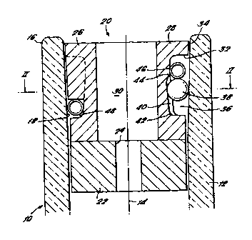
Referring to Figure 1 there is shown a bottle 10
comprising a substantially cylindrical neck portion 12
symmetric about a central axis 14. The neck portion 12 is
defined by a generally cylindrical outer surface 16 and an
inner surface 18 that tapers outwardly at an angle of between
one and two degrees to define a flared mouth portion 20.
Both the bottle 10 and the neck portion 12 are formed of
glass.
Within the neck portion 12 there is disposed a fitment
22 such as, for example, a one-way liquid dispensing valve.
This fitment 22 may be of any convenient design and in the
embodiment shown is provided with a passage 24 coaxial with
the central axis 14 for dispensing the contents of the bottle
10. A removal prevention device 26 is interposed between the
fitment 22 and the mouth of the bottle to prevent the removal
of the fitment from the bottle 10.
Turning to Figure 2, the removal prevention device 26
can be seen to comprise a substantially cylindrical body
portion 28 having a central through bore 30 co~Yi~l with the
central axis 14. Three cut-away regions 32, each spaced by a
120 degrees, are provided within an outer surface 34 of the
body portion 28 and define, with the inner surface of the
neck portion 18, three circumferential openings 36 for the
receipt of a respective ball 38 of a ceramic or other
incompressible material. Within each of these openings 36
there is provided on the body portion 28 a ramp surface 40
which is both arcuate in a cross-section taken perpendicular
to the central axis 14 and inclined to that axis at an angle
of between approximately 4 and 10 degrees. As a result the
distance between the ramp surface 40 and the inner surface of
the neck portion 18 decreases as one moves along the ramp
surface toward the fitment 22.
WO 95/11173 2 1 7 ~4 ~ PCT/GB94/02336
--7--
At an end proximate the fitment 22, the ramp surface 40
terminates in an outwardly directed shoulder 42 that
interconnects the ramp surface with the outer surface of the
body portion 34. By contrast, the opposite and more distal
end of the ramp surface 40 tPrrinAtes in a second, but less
well pronounced, outwardly directed shoulder 44 that
interconnects the ramp surface with a part of the cut-away
region 32 that cooperates with the inner surface of the neck
portion 18 to house a spring 46. The spring 46 extends
circumferentially of the body portion 28 and bears in turn
against each of the balls 38 to urge the balls in the
direction of the fitment 22 and into engagement with both the
ramp surface 40 and the inner surface of the neck portion
18. To this end the spring 46 follows a path which is
somewhat sinusoidal in nature with the spring held at
intervals between the cut-away regions 32 much closer to the
fitment 22 by engagement within a circumferential channel 48.
The body portion 28 may be of any convenient rigid
material and is preferably formed of a suitable metal or of a
thermoset resin such a phenolic resin or melamine
formaldahyde.
In use the fitment 22 may be inserted within the neck
portion 12 in any convenient manner. The removal prevention
device 26 is then presented to the mouth of the bo~tle 10
with the spring 46 retAine~ relative to the body portion 28
by engagement with the circumferential chAn~el 48 and the
balls 38 held loosely in the circumferential opPnings 36. As
the device 26 is pushed home to the position shown in Figure
1 there will be a ten~Ancy for each of the balls 38 to
rise-up its respective ramp surface 40 toward the second
shoulder 44. This is partially because the ramp surfaces 40
are inclined to the central axis 14 at a greater angle than
the inner surface of the neck portion 18 and partially
because the coefficient of friction between the ceramic balls
38 and the glass of the neck portion 12 is greater than that
between the balls and the body portion 28. This ten~Ancy
Wo95/11173 ~ rcTlGBs4lo2336
217~g~ -8-
however, is countered by the action of the spring 46 which
acts to maintain the balls 38 in engagement with their
respective ramp surfaces 40 until the device 26 has been
inserted to such an extent that any movement of the balls 38
away from the ramp surfaces 40 is resisted by the narrowing
of the distance between the ramp surface 40 and the inner
surface of the neck portion 18.
With the fitment and the device in the position shown in
Figure l, the contents of the bottle lO may be dispensed in
the usual way. Thus, if the bottle were to be inverted the
contents would flow through the passage 24 in the fitment 32,
through the communicating through bore 30 in the body portion
28 and out of the mouth of the bottle.
At the same time however, the device 26 serves to
prevent the removal of the fitment 22 from the bottle lO
since to do so the potential counterfeiter must first remove
the device itself. Should he nevertheless attempt to do this
by simply pulling the body portion 28 from the neck portion
12, a state of slip will be established between the ramp
surfaces 40 and the respective balls 38 with which they
engage, with the result that the balls will remain
substantially stationary with respect to both the inner
surface of the neck portion 18 and the fitment 22. This
situation arises as a consequence of the relative angles of
inclination to the central axis 14 of the inner surface 18
and the ramp surfaces 40 as well as a consequence of the
relative coefficients of friction between the materials
employed. These factors combine to enable the respective
points of contact between each of the balls 38 and the inner
surface 18 to resist slip whilst permitting slip between the
balls and their respective ramp surfaces 40.
In another arrangement the angle of inclination of the
ramp surfaces 40 and the relative coefficients of friction
between the ramp surfaces 40 and the balls 38 may be such as
to permit the balls 38 to roll along their respective ramp
surfaces 40 toward the outwardly directed shoulder 42 as the
wossllll73 21 7 4 4 9 ~ PCT/GB94/02336
_g _
body portion 28 is pulled from the neck portion 12. At the
same time however, the relative angle of inclination of the
inner surface 18 and the relative coefficients of friction
between the inner surface 18 and the balls 38 may be such
that this same rolling movement causes the balls 38 to bite
progressively harder and harder into the neck portion 18.
In either event, movement of the balls 38 in the
direction of the withdrawal of the body portion 28 i8
prevented. This iS also the case even if the bottle lO
should be inverted by virtue of the engagement of the balls
with the spring 48 which serves to maintain the balls in
engagement with both the ramp surfaces 40 and the inner
surface of the neck portion 18.
Because of the non-movement of the balls 38 with respect
ot the bottle 10 and the progressively narrower distance
between the ramp surfaces 40 and the inner surface of the
neck portion 18, the outwardly directed force exerted by the
balls on the neck portion 12 increases dramatically as the
device 26 is attempted to be withdrawn from the bottle 10 and
as the point of contact between the balls and their
respective ramp surfaces moves towards the shoulder 42. Long
before the device 26 can be removed from the bottle 10 this
force becomes sufficiently large to shatter the glass of the
neck portic 12 thereby rendering the bottle useless to the
counterfeiter and providing the ultimate temper-evident
signal to innocent third parties.
It will be apparent to those skilled in the art that
whilst the balls 38 have been illustrated as being biased
towards the fitment 22 by means of a spring 38, this need not
necessarily be the case. For example, in the embodiment
shown in Figure 3 the balls 38 are biased towards the fitment
22 by means of a circlip 50.
In another embodiment, shown in Figure 4, the balls 38
are held in position with respect to the body portion 28 by
means of a cage 52. As can be seen, the cage 52, which is
substantially cylindrical in shape, includes respective
WOg5/11173 PcT/Gss4/02336
217~98 lO
circumferential openings 54 for the receipt of the balls 38,
each of which openings is spaced by 120 degrees. However, in
addition to simply ret~ining the balls 38 with respect to the
~ody portion 28, that part of the cage 52 defining each of
the openings 54 is also provided with a respective
downwardly-directed resilient member 56 for engagement with
the balls such that, in use, the balls are biased towards the
fitment 22.
A further example is shown in Figure 5 in which the
circumferential op~ gs 54 are defined by respective
cut-away portions 58 within an outer cylinderical surface 60
of the cage 52.
As shown in Figures 4 and 5, the resilient member 56 may
be formed integrally with both the cage 52 and the body
portion 28 and in so doing provides a removal prevention
device 26 that is particularly easy to insert within the neck
portion 12 of a bottle 10.
Likewise, it will also be apparent that the removal
prevention device 26 may be formed integrally with the
fitment 22 thereby further facilitating the encapsulating of
the bottle and its contents.
Whilst the ramp surfaces 40 have been described as being
arcuate in a cross-section taken perpendicular to the central
axis 14, it will be apparent that this also need not
necessarily be the case. Indeed in cross-section these ramp
Qurfaces 40 may be trianglar, square or any other convenient
shape. One advantage, of providing the body portion 28 with
ramp surfaces 40 that are substantially trianglar in
cross-section is that such a surface provides two points of
contact for each of the balls 38 as shown in Figure 7.
Because none of the lines that may be drawn between the
centres of the balls 38 and their various points of contact
with the body portion 28 intersect the central axis 14, the
reaction forces RF that, in use, are exerted on the body
portion by the balls immediately prior to the shattering of
the neck portion 12 may be absorbed other than through the
WOgS/11173 2 1 7 4 4 9 8 pcTlGs94lo2336
centre of the body portion. As a result the central through
bore 30 may be of increased diameter without compromising the
rigidity of the body portion 28. This in turn leads to an
improvement in the ability of the device 26 to dispense the
contents of the bottle since by having a through bore 30 of
increased diameter it is easier for both air to enter the
bottle and the contents to be poured out.
In an alternative embodiment shown in Figure 8 in which
the ramp surfaces 40 are again of arcuate cross-section, the
body portion 28 is additionally provided with a number of
circumferential cut-away portions 62 at locations
intermediate the cut-away regions 32. In this embodiment
even though the diameter of the central through bore 30 is
limited by the fact that the reaction forces are to be
absorbed through the centre and by the need not to compromise
the rigidity of the body portion 28, an improvement is
obtained in the dispensing of the contents of the bottle
since air is free to enter the bottle lO through the cut-away
portions 62 leaving the through bore 30 for the pouring of
the contents.
Again, whilst the ramp surfaces 40 have been illustrated
as being rectilinear in a plane that contains the central
axis 14, it will be apparent that this again need not
necessarily be the case. Indeed, in a cross-section that
includes the central axis 14, the ramp surfaces 40 may be
flared outwardly towards the fitment 22 so that as the point
of contact between the balls 38 and their respective ramp
surfaces moves towards the shoulder 42, the distance between
the ramp surfaces and the inner surface of the neck portion
18 decreases at a more rapid rate. In this way the outwardly
directed force exerted by the balls 3~ on the neck portion 12
will be increased for a given displacement of the device 26
with respect to the bottle lO.
In an alternative embodiment, the ramp surfaces 40,
instead of being disposed in a plane that contains the
WO95/11173 PCTIGB94/02336
`~
217~4~8 -12-
central axis 14, may extend helically of the body portion
28. In this way the neck portion 12 may still be shattered
even if an attempt is made to unscrew the device 26 from the
bottle 10.
In a preferred embodiment the balls 38 comprises ceramic
spheres of approximately 3mm in diameter. It will be
apparent however, that this need not necessarily be the
case. In alternative embodiments which are not specifically
illustrated the "balls" may be provided with any convenient
rolling surface and as such may be cylinderical or even
barrel-shaped. This flexibility in the design of the "balls"
enables the use of simplified manufacturing techniques which,
whilst not producing a perfect sphere, results in a "ball"
such as that shown in Figure 9 which has a more than adequate
rolling surface 64.
Likewise, it will be apparent that the balls 38 do not
necessarily have to be formed of a ceramic material.
However, it has been found that such a material, along with
stainless steel, has the necessary crush-resistant properties
to withstand the reaction forces exerted on the balls by the
bottle 10 immediately prior to the shattering of the neck
portion 12.
In another embodiment shown in Figure 10, the removal
prevention device 26 comprises three radially disposed sprag
elements 100 which are spaced by a 120 degrees around a
central conduit 102 and interconnected by means of a
serpentine spring member 104. As can be seen more clearly in
Figure 11, each sprag element 100 is substantially planar in
nature and comprises opposed radially inwardly and outwardly
directed arcuate end surfaces 106 and 108 as well as
outwardly tapering upper and lower surfaces 110 and 112. Of
the two opposed radially directed surfaces, the outer surface
108 engages the inner surface of the neck portion 18 while a
heel portion 114 of the inner surface 106 engages the outer
surface 116 of the central conduit 102. The conduit 102,
which communicates with the passage 24 provided in the
WO95/11173 2 1 7 4 4 9 ~ PcT/Gss4/02336
-13-
fitment 22, is flared outwardly toward the mouth of the
bottle 10 and so defines an outwardly directed shoulder 118
at the intersection of the flared portion 120 with the
remainder of the conduit. ~t is with this shoulder 118 that
the heel portion 114 of each of the sprag elements 100
engages.
Although both the end surfaces 104 and 106 are arcuate
in a plane that contains the central axis 14, the two
surfaces have different centres of curvature 122 and 124 that
are displaced with respect to each other. As a result each
sprag element 100 may act as an over-centre locking member.
In use the fitment 22 may be inserted within the neck
portion 12 in any convenient manner. The removal prevention
device 26 is then presented to the mouth of the bottle 10 and
pushed home. By applying a central force to the device 26 in
the direction of insertion in such a way that the conduit 102
engages the fitment 22, each of the sprag elements 100 is
caused to frictionally engage both the inner surface of the
neck portion 18 and the outer surface of the conduit 116. As
a result the overall width of the device 26 in a plane
perpendicular to the central axis 14 is reduced thereby
enabling the sprag elements 100 to adopt the position shown
in Figure 11 in which their respective upper and lower
surfaces 110 and 112 are both inclined downwardly toward the
central axis 14 and in which their respective points of
contact with the conduit 102 are disposed closer to the
fitment 22 than are their respective points of contact with
the inner surface of the neck portion 18.
With the fitment and the device in the position shown in
Figure 11 the contents of the bottle 10 may be dispensed in
the usual way. Thus, if the bottle were to be inverted the
contents would flow through the passage 24 in the fitment 22,
through the communicating conduit 102 and out of the mouth of
WO95/11173 PCT/GB94/02336
217 449 8 ` -` -14-
the bottle by way of the flared portion 120.
At the same time however, the device 26 serves to
prevent the removal of the fitment 22 from the bottle 10
since to do so the potential counterfeiter must again first
remove the device itself. If he should attempt to do this by
simply pulling the conduit 102 out of the bottle 10, each of
the sprag elements 100 would have to pivot about their
respective points of contact with both the inner surface of
the neck portion 18 and with the outer surface of the conduit
116. This time however, instead of tending to decrease the
overall width of the device 26 in a plane perpendicular to
the central axis 14, this movement would tend to increase the
overall width as the upper and lower surfaces 110 and 112 are
pivoted through the horizontal and to a position in which the
points of contact between the respective sprag elements and
the conduit 102 are disposed further from the fitment 22 than
are the points of contact between the sprag elements and the
inner surface of the neck portion 18. During this movement
the forces exerted on the neck portion 12 by each of the
sprag elements 100 increase until they reach a value at which
the glass of the neck portion shatters thereby again
rendering the bottle 10 useless to the counterfeiter.
It will be apparent to those skilled in the art that the
sprag elements 100 may be formed of any convenient rigid
material such as a metal. Having said that however, it has
been found that the coefficient of fiction between some metal
sprag elements 100 and the inner surface of the neck portion
18 is not sufficiently high to prevent the device 26 from
slipping with respect to the bottle should the device be
attempted to be withdrawn. Accordingly, the sprag elements
100, if formed of metal, are preferably also coated on their
respective radially outwardly directed end surfaces 106 with
a suitable material such as ceramic which has an increased
coefficient of friction.
WO95/11173 2 1 7 4 ~ g 8 pcTlGs94lo2336
-15-
In another embodiment shown in Figure 12, the removal
prevention device 26 comprises an open star washer 200
adapted for engagement with a plug 202 that serves shield the
fitment 22. To this end the plug 202 may be isolated from
the fitment 22 or alternatively, as shown, may be provided
with one or more formations 204 with which the fitment may
engage.
As can be seen, the open star washer 200 is part annular
in shape and comprises a rim portion 206 from which they
pro~ect a number of radially inwardly directed pointed teeth
208. The teeth 208 engage an outer surface 210 of the plug
202 which is disposed centrally of the star washer 200 and
which is of substantially frustroconical shape.
In contrast to the previously described embodiments, the
inner surface of the neck portion 18 is provided adjacent the
mouth portion 20 with an undercut region 212.
In use, once the fitment 22 has been inserted within the
neck portion of the bottle 18, the removal prevention device
26 may be presented to the mouth of the bottle 10 and pushed
home. In so doing a central force is applied to the plug 202
in the direction of insertion thereby urging the teeth 208
downwardly with respect to the rim portion 206. As a result
the overall w~dth of the star washer 200 is reduced in a
plane perpendicular to the central axis 14 and this allows
the device 26 to be inserted into the neck portion 12 with
the rim portion 206 in engagement with the undercut region
2.2. Once the insertion force is removed, the star washer
200 springs outwardly for a more secure engagement with the
inner surface of the neck portion 18. Nevertheless the
points at which the various teeth 208 engage the outer
surface of the plug 210 remain closer to the fitment 22 then
do the points at which the rim portion 206 engages the under
cut region 212. Thus again the star washer 200 acts as an
over-centre locking member.
Wo95/11173 PCT/GB94tO2336
217~98 i -16-
With the fitment and device in the position shown in
Figure 12 the contents of the bottle 10 may be dispensed in
the usual way. To this end the plug 202 may be provided with
a central through bore which communicates with the passage 24
provided in the fitment 22. Alternatively reliance may be
placed on the annual spacing 214 between the plug and the
neck portion 12.
At the same time however, the device 26 serves to
prevent the removal of the fitment 22 from the bottle 10
since to do so the potential counterfeiter must again first
remove the device itself. If he should attempt to do this by
extracting the plug 202 from the bottle 10, the teeth 208
which engage the outer surface of the plug 210 would be urged
upwardly with respect to the rim portion 206. Rather than
decreasing the overall width of the star washer 200 in a
plane perpendicular to the central axis 14, this movement
tends to increase that width as the teeth 208 are attempted
to be pivoted through the horizontal to a position in which
they engage the outer surface of the plug 210 at a point
further from the fitment 22 then that at which the rim
portion 206 engages the undercut region 212. As a
consequence the outwardly directed force exerted on the neck
portion 12 by the star washer 200 is increased causing the
device 26 to ~am in position and prevent the further
withdrawal of the plug 202 from the bottle 10.
It will be apparant to those skilled in the art that the
fitment removal prevention devices described above may also
find use in connection with contAi~ers made of materials
other than glass. All that is required is that the mouth
portion of the contAinPr be of a rigid material. Although
there are advantages in the mouth portion being formed of a
frangible material, such as glass, since in this way the
attempted withdrawal of the device may result in the
destruction of the mouth portion, this need not necessarily
be the case. If, for example, the mouth portion were formed
of a rigid but non-frangible material, the attempted
WO95/11173 2 1 7 4 ~ 9 8 PCT/GB94/02336
-17-
withdrawal of the device, whilst not resulting in the
destruction of the mouth portion, would result in the jamming
of the device within the contAinPr and so still prevent the
removal of the fitment.