Note: Descriptions are shown in the official language in which they were submitted.
21 74686
n~rr i rt i ~n
DUAL FORCE ACTUATOR
FOR U.~F. TN FN~'.TNF. RFTARnTNt'.' .~Y.~TFM.
Technic~l Fiel~
The present invention relates generally to
actuators involved in engine retarding systems and,
more particularly, to an actuator that utilizes one
force to take up a lash between the actuator and an
engine valve and another force to open the engine
valve.
R~ckgrolln~ Art
Engine brakes or retarders are used to
assist and supplement wheel brakes in slowing heavy
vehicles, such as tractor-trailers. Engine brakes are
desirable because they help alleviate wheel brake
overheating. As vehicle design and technology have
advanced, the hauling capacity of tractor-trailers has
increased, while at the same time rolling resistance
and wind resistance have decreased. Thus, there is a
need for advanced engine braking systems in today's
heavy vehicles.
Problems with existing engine braking
systems include high noise levels and a lack of smooth
operation at some braking levels resulting from the
use of less than all of the engine cylinders in a
compression braking scheme. Also, existing systems
are not readily adaptable to differing road and
vehicle conditions. Still further, existing systems
are complex and expensive.
Known engine compression brakes convert an
internal combustion engine from a power generating
unit into a power consuming air compressor.
2~ 74686
U.S. Patent No. 3,220,392 issued to Cummins
on 30 November 1965, discloses an engine braking
system in which an exhaust valve located in a cylinder
is opened when the piston in the cylinder nears the
top dead center (TDC) position on the compression
stroke. An actuator includes a master piston, driven
by a cam and pushrod, which in turn drives a slave
piston to open the exhaust valve during engine
braking. The braking that can be accomplished by the
Cummins device is limited because the timing and
duration of the opening of the exhaust valve is
dictated by the geometry of the cam which drives the
master piston and hence these parameters cannot be
independently controlled.
U.S. Patent No. 5,012,778 issued to Pitzi on
7 May 1991, discloses an engine braking system which
includes a solenoid actuated servo valve hydraulically
linked to an exhaust valve actuator. The exhaust
valve actuator comprises a piston which, when
subjected to sufficient hydraulic pressure, is driven
into contact with a contact plate attached to an
exhaust valve stem, thereby opening the exhaust valve.
U.S. Patent No. 4,572,114 issued to Sickler
on 25 February 1986, discloses an electronically
controlled engine braking system. A pushtube of the
engine reciprocates a rocker arm and a master piston
so that pressurized fluid is delivered and stored in a
high pressure accumulator. For each engine cylinder,
a three-way solenoid valve is operable by an
electronic controller to selectively couple the
accumulator to a slave bore having a slave piston
disposed therein. The slave piston is responsive to
the admittance of the pressurized fluid from the
accumulator into the slave bore to move an exhaust
21 74686
- valve crosshead and thereby open a pair of exhaust
valves.
Braking systems have been developed that
control the lash take-up between an actuator and an
exhaust valve.
Actuators in engine braking systems require
a lash, i.e., a minimum cold clearance, between an
actuator and the exhaust valve to prevent the exhaust
valve from opening prematurely when the exhaust valve
expands due to engine heat. The lash, however,
affects the timing of opening and closing the exhaust
valve. To overcome this problem, prior braking
systems have employed methods that keep the valve-
actuating mechanism engaged with the exhaust valve,
thereby eliminating the lash.
For example, U.S. Patent No. 4,898,128
issued to Meneely on 6 February 1990, discloses an
anti-lash adapter which includes a slave piston
adapted to contact an exhaust valve crosshead. The
slave piston is biased by springs disposed on opposite
sides of the slave piston, and is further disposed in
fluid communication with a master piston. The lash
between the slave piston and the crosshead is taken up
by the net forces acting on the slave piston before
the master piston is displaced. Thereafter,
displacement of the master piston causes the slave
piston to force exhaust vales open via the crosshead.
n;~lnsllr~ of thP Tnv~nt; nn
The present invention comprises a dual force
actuator which is engageable with an exhaust valve of
an engine.
More particularly, in accordance with one
aspect of the present invention, an actuator for
moving an exhaust valve to an open position includes a
2~ 74686
piston having a central bore therethrough and
engageable with the exhaust valve and a valve spool
disposed in the central bore and movable therein
relative to the piston wherein the piston and valve
spool are disposed in an actuator receiving bore.
Means are provided for resiliently interconnecting the
piston and the valve spool and means are also provided
for admitting pressurized fluid into the actuator
receiving bore to act against the piston and valve
spool so that the piston engages the exhaust valve
with a first force exerted by the interconnecting
means and so that the piston thereafter engages the
exhaust valve with a second force exerted by the
pressurized fluid.
Preferably, the second force is greater than
the first force. Also preferably, the interconnecting
means includes a second spring disposed on a second
side of the slave piston in compression between the
slave piston and a member defining the actuator
receiving bore. The first spring preferably has a
first spring rate and the second spring preferably has
a second spring rate less than the first spring rate.
The valve spool may include a high pressure
annulus that receives high pressure fluid and the
slave piston may include a passage leading to one side
of the slave piston. The valve spool and the slave
piston are relatively movable after the slave piston
contact the exhaust valve to place the high pressure
annulus in fluid communication with the passage.
The valve spool may further include a low
pressure annulus that is coupled to a low pressure
source and the valve spool may be movable relative to
the slave piston to connect the low pressure annulus
to the passage when the exhaust valve is to be closed.
2 1 74686
-
In accordance with a further aspect of the
present invention, a dual force actuator for an engine
braking system to engage and move an exhaust valve to
an open position includes a source of high pressure
fluid, a main body having an actuator receiving bore
therein in communication with the source of high
pressure fluid and a slave fluid control device
engageable with the exhaust valve and disposed in the
actuator receiving bore wherein the slave fluid
control device has a passage therethrough. A master
fluid control device is disposed adjacent to the slave
fluid control device and includes a high pressure
annulus coupled to the source of high pressure fluid.
The master fluid control device is movable relative to
the slave fluid control device to interconnect the
passage with the high pressure annulus. A spring is
disposed in compression between the master fluid
control device and a first side of the slave fluid
control device. High pressure fluid from high
pressure fluid source urges the master fluid control
device against the spring such that the spring exerts
a spring force against the slave fluid control device
until the slave fluid control device contacts the
exhaust valve. The master fluid control device
thereafter moves relative to the slave fluid control
device to cause the passage to be placed into fluid
communication with the high pressure annulus such that
the slave fluid control device drives the exhaust
valve to the open position under the influence of the
high pressure fluid.
The present invention develops a first force
to take up the lash between an actuator pin and the
exhaust valve. Then, automatically, the actuator
generates a second, stronger force to open the exhaust
valve. This arrangement has the advantage of reducing
21 74686
_
wear and tear between the actuator pin and the exhaust
valve.
Other features and advantages are inherent
in the apparatus claimed and disclosed or will become
apparent to those skilled in the art from the
following detailed description in conjunction with the
accompanying drawings.
Rr;f~f n~:~r;~ti~ n f th~ nr~win~c
Fig. 1 is a fragmentary isometric view of an
internal combustion engine with portions removed to
reveal detail therein and with which the braking
control of the present invention may be used;
Fig. 2 comprises a sectional view of the
engine of Fig. 1;
Fig. 3 comprises a graph illustrating
cylinder pressure as a function of crankshaft angle in
braking and motoring modes of operation of an engine;
Fig. 4A comprises a graph illustrating
braking power as a function of compression release
timing of an engine;
Fig. 4B comprises a graph illustrating
percent braking horsepower as a function of valve open
duration;
Fig. 5 comprises a combined block and
schematic diagram of a braking control according to
the present invention;
Fig. 6 comprises a combined block and
schematic diagram of an alternative embodiment of the
brake control of the present invention;
Fig. 7 comprises a perspective view of
hydromechanical hardware for implementing the control
of the present invention;
Fig. 8 comprises an end elevational view of
the hardware of Fig. 7;
21 74686
- Fig. 9 comprises a plan view of the hardware
of Fig. 7 with structures removed therefrom to the
right of the section line 12-12 to more clearly
illustrate the design thereof;
Figs. 10 and 11 are front and rear
elevational views, respectively, of the hardware of
Fig. 9;
Figs. 12, 13, 14, 15 and 17 are sectional
views taken generally along the lines 12-12, 13-13,
14-14, 15-15 and 17-17, respectively, of Fig. 9;
Fig. 16 is an enlarged fragmentary view of a
portion of Fig. 15;
Figs. 18 and 19 are composite sectional
views illustrating the operation of the actuator of
Figs. 7-17;
Fig. 20 is a block diagram illustrating
output and driver circuits of an engine control module
(ECM), a plurality of unit injectors and a plurality
of braking controls according to the present
invention;
Fig. 21 comprises a block diagram of the
balance of electrical hardware of the ECM;
Fig. 22 comprises a three-dimensional
representation of a map relating solenoid control
valve actuation and deactuation timing as a function
of desired braking magnitude and turbocharger boost
magnitude;
Fig. 23 comprises a block diagram of
software executed by the ECM to implement the braking
control module of Fig. 21;
Fig. 24 is a graph illustrating exhaust
valve lift as a function of crankshaft angle;
Fig. 25 is a graph illustrating cylinder
pressure and exhaust manifold pressure as a function
of crankshaft angle;
- 2 1 74686
- Fig. 26 is a sectional view similar to Fig.
12 illustrating an alternative accumulator according
to the present invention;
Figs. 27-29 are sectional views similar to
Fig. 17 illustrating alternative actuators according
to the present invention; and
Fig. 30 is a view similar to Fig. 16
illustrating a poppet valve which may be substituted
for the valve of Figs. 15-19 according to an
alternative embodiment of the present invention.
Best Mode for Carrying Out the Invention
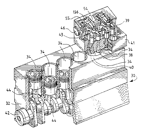
Referring now to Fig. 1, an internal
combustion engine 30, which may be of the four-cycle,
compression ignition type, undergoes a series of
engine events during operation thereof. In the
preferred embodiment, the engine sequentially and
repetitively undergoes intake, compression, combustion
and exhaust cycles during operation. The engine 30
includes a block 32 within which is formed a plurality
of combustion chambers or cylinders 34, each of which
includes an associated piston 36 therein. Intake
valves 38 and exhaust valves 40 are carried in a head
41 bolted to the block 32 and operated to control the
admittance and expulsion of fuel and gases into and
out of each cylinder 34. A crankshaft 42 is coupled
to and rotated by the pistons 36 via connecting rods
44 and a camshaft 46 is coupled to and rotates with
the crankshaft 42 in synchronism therewith. The
camshaft 46 includes a plurality of cam lobes 48 (one
of which is visible in Fig. 2) which are contacted by
cam followers 50 (Fig. 2) carried by rocker arms 54,
55 which in turn bear against intake and exhaust
valves 38, 40, respectively.
2 1 74686
g
-
In the engine 30 shown in Figs. i and 2,
there is a pair of intake valves 38 and a pair of
exhaust valves 40 per cylinder 34 wherein the valve 38
or 40 of each pair is interconnected by a valve bridge
39, 43, respectively. Each cylinder 34 may instead
have a different number of associated intake and
exhaust valves 38, 40, as necessary or desirable.
The graphs of Figs. 3 and 4A illustrate
cylinder pressure and braking horsepower,
respectively, as a function of crankshaft angle
relative to top dead center (TDC). As seen in Fig. 3,
during operation in a braking mode, the exhaust valves
40 of each cylinder 34 are opened at a time t1 prior to
TDC so that the work expended in compressing the gases
within the cylinder 34 is not recovered by the
crankshaft 42. The resulting effective braking by the
engine is proportional to the difference between the
area under the curve 62 prior to TDC and the area
under the curve 62 after TDC. This difference, and
hence the effective braking, can be changed by
changing the time t1 at which the exhaust valves 40 are
opened during the compression stroke. This
relationship is illustrated by the graph of Fig. 4A.
As seen in Fig. 4B, the duration of time the
exhaust valves are maintained in an open state also
has an effect upon the maximum braking horsepower
which can be achieved.
With reference now to Fig. 5, a two-cylinder
portion 70 of a brake control according to the present
invention is illustrated. The portion 70 of the brake
control illustrated in Fig. 5 is operated by an
electronic control module (ECM) 72 to open the exhaust
valves 40 of two cylinders 34 with a selectable timing
and duration of exhaust valve opening. For a six
cylinder engine, up to three of the portions 70 in
2t 74686
- --10--
- Fig. 5 could be connected to the ECM 72 so that engine
braking is accomplished on a cylinder-by-cylinder
basis. Alternatively, fewer than three portions 70
could be used and/or operated so that braking is
accomplished by less than all of the cylinders and
pistons. Also, it should be noted that the portion 70
can be modified to operate any other number of exhaust
valves for any other number of cylinders, as desired.
The ECM 72 operates a solenoid control valve 74 to
couple a conduit 76 to a conduit 78. The conduit 76
receives engine oil at supply pressure, and hence
operating the solenoid control valve 74 permits engine
oil to be delivered to conduits 80, 82 which are in
fluid communication with check valves 84, 86,
respectively. The engine oil under pressure causes
pistons of a pair of reciprocating pumps 88, 90 to
extend and contact drive sockets of injector rocker
arms (described and shown below). The rocker arms
cause the pistons to reciprocate and cause oil to be
supplied under pressure through check valves, 92, 94
and conduits 96, 98 to an accumulator 100. As such
pumping is occurring, oil continuously flows through
the conduits 80 and 82 to refill the pumps 88, 90.
In the preferred embodiment, the accumulator
does not include a movable member, such as a piston or
bladder, although such a movable member could be
included therein, if desired. Further, the
accumulator includes a pressure control valve 104
which vents engine oil to sump when a predetermined
pressure is exceeded, for example 6,000 p.s.i.
The conduit 96 and accumulator 100 are
further coupled to a pair of solenoid control valves
106, 108 and a pair of servo-actuators 110, 112. The
servo-actuators 110, 112 are coupled by conduits 114,
116 to the pumps 88, 90 via the check valves 84, 86,
2 1 74686
_
--11--
respectively. The solenoid control valves 106, 108
are further coupled by conduits 118, 120 to sump.
As noted in greater detail hereinafter, when
operation in the braking mode is selected by an
operator, the ECM 72 closes the solenoid control valve
74 and operates the solenoid control valves 106, 108
to cause the servo-actuators 110, 112 to contact valve
bridges 43 and open associated exhaust valves 40 in
associated cylinders 34 near the end of a compression
stroke. It should be noted that the control of Fig. 5
may be modified such that a different number of
cylinders is serviced by each accumulator. In fact,
by providing an accumulator with sufficient capacity,
all of the engine cylinders may be served thereby.
Fig. 6 illustrates an alternative embodiment
of the present invention wherein elements common to
Figs. 5 and 6 are assigned like reference numbers. In
the embodiment of Fig. 6, the solenoid control valve
74, the check valves 84, 86, 92 and 94 and the pumps
88 and 90 are replaced by a high pressure pump 130
which is controlled by the ECM 72 to pressurize engine
oil to a high level, for example, 6,000 p.s.i.
Figs. 7-17 illustrate mechanical hardware
for implementing the control of Fig. 5. Referring
first to Figs. 7-11, a main body 132 includes a
bridging portion 134. Threaded studs 135 extend
through the main body 132 and spacers 136 into the
head 41 and nuts 137 are threaded onto the studs 135.
In addition, four bolts 138 extend through the main
body 132 into the head 41. The bolts 138 replace
rocker arm shaft hold down bolts and not only serve to
secure the main body 132 to the head 41, but also
extend through and hold a rocker arm shaft 139 in
position.
21 74686
-
-12-
- A pair of actuator receiving bores 140, 142
are formed in the bridging portion 134. The servo-
actuator 110 is received within the actuator receiving
bore 140 while the servo-actuator 112 (not shown in
Figs. 7-17) is received within the receiving bore 142.
Inasmuch as the actuators 110 and 112 are identical,
only the actuator 110 will be described in greater
detail hereinafter.
With specific reference to Figs. 12-14, a
10- cavity 146, seen in Fig. 12, is formed within the
bridging portion 134 and comprises the accumulator 100
described above. The cavity 146 is in fluid
communication with a high pressure passage or manifold
148 which is in turn coupled by the check valve 92 and
a passage 149 to a bore 150 forming a portion of the
pump unit 88. A piston 152 is disposed within the
bore 150 (the top of which is just visible in Fig. 13)
and is coupled to a connecting rod 154 which is
adapted to contact a fuel injector rocker arm 156,
seen in Figs. 1 and 7. A spring 157 surrounds the
connecting rod 154 and is disposed between a shoulder
on the connecting rod 154 and a stop 158. With
reference to Fig. 13, reciprocation of the fuel
injector rocker arm 156 alternately introduces
crankcase oil through an inlet fitting 159 (seen only
in Figs. g and 10) and a pump inlet passage 160 past a
ball 162 of the check valve 84 into an intermediate
passage 164 and expulsion of the pressurized oil from
the intermediate passage 164 into the high pressure
passage 148 past a ball 166 of the check valve 92.
The pressurized oil is retained in the cavity 146 and
further is supplied via the passage 148 to the
actuator 110.
Referring now to Figs. 15 and 16, the
passage 148 is in fluid communication with passages
2 1 74686
-
-13-
- 170, 172 leading to the actuator receiving bore 140
and a valve bore 174, respectively. A ball valve 176
is disposed within the valve bore 174. The solenoid
control valve 106 is disposed adjacent the ball valve
176 and includes a solenoid winding shown
schematically at 180, an armature 182 adjacent the
solenoid winding 180 and in magnetic circuit therewith
and a load adapter 184 secured to the armature 182 by
a screw 186. The armature 182 is movable in a recess
defined in part by the solenoid winding 180, an
armature spacer 185 and a further spacer 187. The
solenoid winding 180 is energizable by the ECM 72, as
noted in greater detail hereinafter, to move the
armature 182 and the load adapter-184 against the
force exerted by a return spring illustrated
schematically at 188 and disposed in a recess 189
located in a solenoid body 191.
The ball valve includes a rear seat 190
having a passage 192 therein in fluid communication
with the passage 172 and a sealing surface 194. A
front seat 196 is spaced from the rear seat 190 and
includes a passage 198 leading to a sealing surface
200. A ball 202 resides in the passage 198 between
the sealing surfaces 194 and 200. The passage 198
comprises a counterbore having a portion 201 which has
been cross-cut by a keyway cutter to provide an oil
flow passage to and from the ball area.
As seen in phantom in Figs. 9 and 15, a
passage 204 extends from a bore 206 containing the
front seat 196 to an upper portion 208 of the
receiving bore 140. As seen in Fig. 17, the receiving
bore 140 further includes an intermediate portion 210
which closely receives a master fluid control device
in the form of a valve spool 212 having a seal 214
which seals against the walls of the intermediate
21 74686
- portion 210. The seal 214 is commercially available
and is of two-part construction including a carbon
fiber loaded teflon ring backed up and pressure loaded
by an O-ring. The valve spool 212 further includes an
enlarged head 216 which resides within a recess 218 of
a lash stop adjuster 220. The lash stop adjuster 220
includes external threads which are engaged by a
threaded nut 222 which, together with a washer 224,
are used to adjust the axial position of the lash stop
adjuster 220. The washer 224 is a commercially
available composite rubber and metal washer which not
only loads the adjuster 220 to lock the adjustment,
but also seals the top of the actuator 110 and
prevents oil leakage past the nut 222.
A slave fluid control device in the form of
a piston 226 includes a central bore 228, seen in
Figs. 17-19, which receives a lower end of the spool
212. A spring 230 is placed in compression between a
snap ring 232 carried in a groove in the spool 212 and
an upper face of the piston 226. A return spring,
shown schematically at 234, is placed in compression
between a lower face of the piston 226 and a washer
236 placed in the bottom of a recess defined in part
by an end cap 238. An actuator pin 240 is press-
fitted within a lower portion of the central bore 228
so that the piston 226 and the actuator pin 240 move
together. The actuator pin 240 extends outwardly
through a bore 242 in the end cap 238 and an 0-ring
244 prevents the escape of oil through the bore 242.
In addition, a swivel foot 246 is pivotally secured to
an end of the actuator pin 240.
The end cap 238 is threaded within a
threaded portion 247 of the receiving bore 140 and an
0-ring 248 provides a seal against leakage of oil.
2 1 74686
-15-
-
- As seen in Fig. 9, an oil return passage 250
extends between a lower recess portion 252, defined by
the end cap 238 and the piston 226, and the inlet
passage 160 just upstream of the check valve 84.
In addition to the foregoing, as seen in
Figs. 15, 18 and 19, an oil passage 254 is disposed
between the lower recess portion 252 and a space 256
between the valve spool 212 and the actuator pin 240
to prevent hydraulic lock between these two
components.
Industrial Applicability
Figs. 18 and 19 are composite sectional
views illustrating the operation of the present
invention in detail. When braking is commanded by an
operator and the solenoid 74 is actuated by the ECM
72, oil is supplied to the inlet passage 160 (seen in
Figs. 9 and 13). As seen in Fig. 13, the oil flows at
supply pressure past the check valve 84 into the
passage 149 and the bore 150, causing the piston 152
and the connecting rod 154 to move downwardly into
contact with the fuel injector rocker arm against the
force of the spring 157. Reciprocation of the
connecting rod 154 by the fuel injector rocker arm 156
causes the oil to be pressurized and delivered to the
passage 148. The pressurized oil is thus delivered
through the passage 172 and the passa~ge 192 in the
rear seat 190, as seen in Fig. 18.
When the ECM 72 commands opening of the
exhaust valves 40 of a cylinder 34, the ECM 72
energizes the solenoid winding 180, causing the
armature 182 and the load adapter 184 to move to the
right as seen in Fig. 18 against the force of the
return spring 188. Such movement permits the ball 202
to also move to the right into engagement with the
`- 21 74686
- -16-
- sealing surface 200 (Fig. 16) under the influence of
the pressurized oil in the passage 192, thereby
permitting the pressurized oil to pass in the space
between the ball 202 and the sealing surface 194. The
pressurized oil flows through the passage 198 and the
bore 206 into the passage 204 and the upper portion
208 of the receiving bore 140. The high fluid
pressure on the top of the valve spool 212 causes it
to move downwardly. The spring rate of the spring 230
is selected to be substantially higher than the spring
rate of the return spring 234, and hence movement of
the valve spool 212 downwardly tends to cause the
piston 226 to also move downwardly. Such movement
continues until the swivel foot takes up the lash and
contacts the exhaust rocker arm 55. At this point,
further travel of the piston 226 is temporarily
prevented owing to the cylinder compression pressures
on the exhaust valves 40. However, the high fluid
pressure exerted on the top of the valve spool 212 is
sufficient to continue moving the valve spool 212
downwardly against the force of the spring 230.
Eventually, the relative movement between the valve
spool 212 and the piston 226 causes an outer high
pressure annulus 258 and a high pressure passage 260
(Figs. 15, 18 and 19) in fluid communication with the
passage 170 to be placed in fluid communication with a
piston passage 262 via an inner high pressure annulus
264. Further, a low pressure annulus 266 of the spool
212 is taken out of fluid communication with the
piston passage 262.
The high fluid pressure passing through the
piston passage 262 acts on the large diameter of the
piston 226 so that large forces are developed which
cause the actuator pin 240 and the swivel foot 246 to
overcome the resisting forces of the compression
21 74686
-17-
- pressure and valve spring load exerted by valve
springs 267 (Figs. 7 and 8). As a result, the exhaust
valves 40 open and allow the cylinder to start blowing
down pressure. During this time, the valve spool 212
travels with the piston 226 in a downward direction
until the enlarged head 216 of the valve spool 212
contacts a lower portion 270 of the lash stop adjuster
220. At this point, further travel of the valve spool
212 in the downward direction is prevented while the
piston 226 continues to move downwardly. As seen in
Fig. 19, the inner high pressure annulus 264 is
eventually covered by the piston 226 and the low
pressure annulus 266 is uncovered. The low pressure
annulus 266 is coupled by a passage 268 (Figs. 15, 18
and 19) to the lower recess portion 252 which, as
noted previously, is coupled by the oil return passage
250 to the pump inlet 160. Hence, at this time, the
piston passage 262 and the upper face of the piston
226 are placed in fluid communication with low
pressure oil. High pressure oil is vented from the
cavity above the piston 226 and the exhaust valves 40
stop in the open position.
Thereafter, the piston 226 slowly oscillates
between a first position, at which the inner high
pressure annulus 264 is uncovered, and a second
position, at which the low pressure annulus 266 is
uncovered, to vent oil as necessary to maintain the
exhaust valves 40 in the open position as the cylinder
34 blows down. During the time that the exhaust
valves 40 are in the open position, the ECM 72
provides drive current according to a predetermined
schedule to provide good coil life and low power
consumption.
When the exhaust valves 40 are to be closed,
the ECM 72 terminates current flow in the solenoid
2 1 74686
- -18-
- winding 180. The return spring 188 then moves the
load adapter 184 to the left as seen in Figs. 18 and
19 so that the ball 202 is forced against the sealing
surface 194 of the rear seat 190. The high pressure
fluid above the valve spool 212 flows back through the
passage 204, the bore 206, a gap 274 between the load
adapter 184 and the front seat 196 and a passage 276
to the oil sump. In response to the venting of high
pressure oil, the valve spool 212 is moved upwardly
under the influence of the spring 230. As the valve
spool 212 moves upwardly, the low pressure annulus 266
is uncovered and the high pressure annulus 258 is
covered by the piston 226, thereby causing the high
pressure oil above the piston 226 to be vented. The
return spring 234 and the exhaust valve springs 267
force the piston 226 upwardly and the exhaust valves
40 close. The closing velocity is controlled by the
flow rate past the ball 202 into the passage 276. The
valve spool 212 eventually seats against an upper
surface 280 of the lash stop adjuster 220 and the
piston 226 returns to-the original position as a
result of venting of oil through the inner high
pressure annulus 264 and the low pressure annulus 266
such that the passage 268 is in fluid communication
with the latter. As should be evident to one of
ordinary skill in the art, the stopping position of
the piston 226 is dependent upon the spring rates of
the springs 230, 234. Oil remaining in the lower
recess portion 252 is returned to the pump inlet 160
via the oil return passage 250.
The foregoing sequence of events is repeated
each time the exhaust valves 40 are opened.
When the braking action of the engine is to
be terminated, the ECM 72 closes the solenoid valve 74
and rapidly cycles the solenoid control valve 106 (and
21 74686
--19--
- the other solenoid control valves) a predetermined
number of cycles to vent off the stored high pressure
oil to sump.
Fig. 20 and 21 illustrate output and driver
circuits of the ECM 72 as well as the wiring
interconnections between the ECM 72 and a plurality of
electronically controlled unit fuel injectors 300a-
300f, which are individually operated to control the
flow of fuel into the engine cylinders 34, and the
solenoid control valves of the present invention, here
illustrated as including the solenoid control valves
106, 108 and additional solenoid valves 301a-301d. Of
course, the number of solenoid control valves would
vary from that shown in Fig. 20 in dependence upon the
number of cylinders to be used in engine braking. The
ECM 72 includes six solenoid drivers 302a-302f, each
of which is coupled to a first terminal of and
associated with one of the injectors 300a-300f and one
of the solenoid control valves 106, 108 and 301a-301d,
respectively. Four current control circuits 304, 306,
308 and 310 are also included in the ECM 72. The
current control circuit 304 is coupled by diodes Dl-D3
to second terminals of the unit injectors 300a-300c,
respectively, while the current control circuit 306 is
coupled by diodes D4-D6 to second terminals of the
unit injectors 300d-300f, respectively. In addition,
the current control circuit 308 is coupled by diodes
D7-D9 to second terminals of the brake control
solenoids 106, 108 and 301a, respectively, whereas the
current control circuit 310 is coupled by diodes D10-
D12 to second terminals of the brake control solenoids
301b-301d, respectively. Also, a solenoid driver 312
is coupled to the solenoid 74.
In order to actuate any particular device
300a-300f, 106, 108 or 301a-301d, the ECM 72 need only
21 74686
- -20-
actuate the appropriate driver 302a-302f and the
appropriate current control circuit 304-310. Thus,
for example, if the unit injector 300a is to be
actuated, the driver 302a is operated as is the
current control circuit 304 so that a current path is
established therethrough. Similarly, if the solenoid
control valve 301d is to be actuated, the driver 302f
and the current control circuit 310 are operated to
establish a current path through the control valve
301d. In addition, when one or more of the control
valves 106, 108 or 301a-301d are to be actuated, the
solenoid driver 312 is operated to deliver current to
the solenoid 74, except when the solenoid control
valve 106 is rapidly cycled as noted above.
It should be noted that when the ECM 72 is
used to operate the fuel injectors 300a-300f alone and
the brake control solenoids 106, 108 and 301a-301d are
not included therewith, a pair of wires are connected
between the ECM 72 and each injector 300a-300f. When
the brake control solenoids 106, 108 and 301a-301d are
added to provide engine braking capability, the only
further wires that must be added are a jumper wire at
each cylinder interconnecting the associated brake
control solenoid and fuel injector and a return wire
between the second terminal of each brake control
solenoid and the ECM 72. The diodes Dl-D12 permit
multiplexing of the current control circuits 304-310;
i.e., the current control circuits 304-310 determine
whether an associated injector or brake control is
operating. Also, the current versus time wave shapes
for the injectors and/or solenoid control valves are
controlled by these circuits.
Fig. 21 illustrates the balance of the ECM
72 in greater detail, and, in particular, circuits for
commanding proper operation of the drivers 302a-302f
21 74686
-
-21-
-
- and the current control circuits 304, 306, 308 and
310. The ECM 72 is responsive to the output of a
select switch 330, a cam wheel 332 and a sensor 334
and a drive shaft gear 336 and a sensor 338. The ECM
72 develops drive signals on lines 340a-340j which are
provided to the drivers 302a-302f and to the current
control circuits 304, 306, 308 and 310, respectively,
to properly energize the windings of the solenoid
control valves 106, 108 and 301a-301d. In addition, a
signal is developed on a line 341 which is supplied to
the solenoid driver 312 to operate same. The select
switch 330 may be manipulated by an operator to select
a desired magnitude of braking, for example, in a
range between zero and 100% braking. The output of
the select switch 330 is passed to a high wins circuit
342 in the ECM 72, which in turn provides an output to
a braking control module 344 which is selectively
enabled by a block 345 when engine braking is to
occur, as described in greater detail hereinafter.
The braking control module 344 further receives an
engine position signal developed on a line 346 by the
cam wheel 332 and the sensor 334. The cam wheel is
driven by the engine camshaft 46 (which is in turn
driven by the crankshaft 42 as noted above) and
includes a plurality of teeth 348 of magnetic
material, three of which are shown in Fig. 21, and
which pass in proximity to the sensor 334 as the cam
wheel 332 rotates. The sensor 334, which may be a
Hall effect device, develops a pulse type signal on
the line 346 in response to passage of the teeth 348
past the sensor 334. The signal on the line 346 is
also provided to a cylinder select circuit 350 and a
differentiator 352. The differentiator 352 converts
the position signal on the line 346 into an engine
speed signal which, together with the cylinder select
2 1 74686
-22-
- circuit 350 and the signal developed on the line 346,
instruct the braking control module 344, when enabled,
to provide control signals on the lines 340a-340f with
the proper timing. Further, when the braking control
module 344 is enabled, a signal is developed on the
line 341 to activate the solenoid drive 312 and the
solenoid 74.
The sensor 338 detects the passage of teeth
on the gear 336 and develops a vehicle speed signal on
a line 354 which is provided to a noninverting input
of a summer 356. An inverting input of the summer 356
receives a signal on a line 358 representing a desired
speed for the vehicle. The signal on the line 358 may
be developed by a cruise control or any other speed
setting device. The resulting error signal developed
by the summer 356 is provided to the high wins circuit
342 over a line 360. The high wins circuit 342
provides the signal developed by the select switch 330
or the error signal on the line 360 to the braking
control module 344 as a signal %BRAKING on a line 361
in dependence upon which signal has the higher
magnitude. If the error signal developed by the
summer 356 is negative in sign and the signal
developed by the select switch 330 is at a magnitude
commanding no (or 0%) braking, the high wins circuit
342 instructs the braking control module 344 to
terminate engine braking.
A boost control module 362 is responsive to
a signal, called BOOST, developed by a sensor 364 on a
line 365 which detects the magnitude of intake
manifold air pressure of a turbocharger 366 of the
engine 30. In the preferred embodiment, the
turbocharger 366 has a variable blade geometry which
allows boost level to be controlled by the boost
control module 362. The module 362 receives a limiter
2 1 74686
_
-23-
-
- signal on a line 368 developed by the braking control
module 344 which allows for as much boost as the
turbocharger 366 can develop under the current engine
conditions but prevents the boost control module from
increasing boost to a level which would cause damage
to engine components.
The braking control module includes a lookup
table or map 370 which is addressed by the signals
%BRAKING and BOOST on the lines 361 and 365,
respectively, and provides output signals DEG. ON and
DEG. OFF to the control of Fig. 23. Fig. 22
illustrates in three dimensional form the contents of
the map 370 including the output signals DEG. ON and
DEG. OFF as a function of the addressing signals
%BRAKING and BOOST. The signals DEG. ON and DEG. OFF
indicate the timing of solenoid control valve
actuation and deactuation, respectively, in degrees
after a cam marker signal is produced by the cam wheel
332 and the sensor 334. Specifically, the cam wheel
332 includes 24 teeth, 21 of which are identical to
one another and each of which occupies 80% of a tooth
pitch with a 20% gap. Two of the remaining three
teeth are adjacent to one another (i.e., consecutive)
while the third is spaced therefrom and each occupies
50% of a tooth pitch with a 50% gap. The ECM 72
detects these non-uniformities to determine when
cylinder number 1 of the engine 30 reaches TDC between
compression and power strokes as well as engine
rotation direction.
The signal DEG ON is provided to a
computational block 372 which is responsive to the
engine speed signal developed by the block 352 of Fig.
21 and which develops a signal representing the time
after a reference point or marker on the cam wheel 332
passes the sensor 334 at which a signal on one of the
- 21 7~686
-24-
- lines 340a-340f is to be switched to a high state. In
like fashion, a computational block 374 is responsive
to the engine speed signal developed by the block 352
and develops a signal representing the time after the
reference point passes the sensor 334 at which the
signal on the same line 340a-340f is to be switched to
an off state. The signals from the blocks 372, 374
are supplied to delay blocks 376, 378, respectively,
which develop on and off signals for a solenoid driver
block 380 in dependence upon the marker developed by
the cam wheel 332 and the sensor 334 and in dependence
upon the particular cylinder which is to be employed
next in braking. The signal developed by the delay
block 376 comprises a narrow pulse having a leading
edge which causes the solenoid driver block 380 to
develop an output signal having a transition from a
low state to a high state whereas the timer block 378
develops a narrow pulse having a leading edge which
causes the output signal developed by the solenoid
driver circuit 380 to switch from a high state to a
low state. The signal developed by solenoid driver
circuit 380 is routed to the appropriate output line
340a-340f by a cylinder select switch 382 which is
responsive to the cylinder select signal developed by
the block 350 of Fig. 21.
The braking control module 344 is enabled by
the block 345 in dependence upon certain sensed
conditions as detected by sensors/switches 383. The
sensors/switches include a clutch switch 383a which
detects when a clutch of the vehicle is engaged by an
operator (i.e., when the vehicle wheels are disengaged
from the vehicle engine), a throttle position switch
383b which detects when a throttle pedal is depressed,
an engine speed sensor 383c which detects the speed of
the engine, a service brake switch 383d which develops
2 1 74686
-25-
- a signal representing whether the service brake pedal
of the vehicle is depressed, a cruise control on/off
switch 383e and a brake on/off switch 383f. If
desired, the output of the circuit 352 may be supplied
in lieu of the signal developed by the sensor 383c, in
which case the sensor 383c may be omitted. According
to a preferred embodiment of the present invention,
the braking control module 344 is enabled when the
on/off switch 383f is on, the engine speed is above a
particular level, for example 950 rpm, the driver's
foot is off the throttle and clutch and the cruise
control is off. The braking control module 344 is
also enabled when the on/off switch 383f is on, engine
speed is above the certain level, the driver's foot is
off the throttle and clutch, the cruise control is on
and the driver depresses the service brake. Under the
second set of conditions, and also in accordance with
the preferred embodiment, a "coast" mode may be
employed wherein engine braking is engaged only while
the driver presses the service brake, in which case,
the braking control module 344 is disabled when the
driver's foot is removed from the service brake.
According to an optional "latched" mode of operation
operable under the second set of conditions as noted
above, the braking control module 344 is enabled by
the block 345 once the driver presses the service
brake and remains enabled until another input, such as
depressing the throttle or selecting 0~ braking by
means of the switch 330, is supplied.
The block 345 enables an injector control
module 384 when the braking control module 344 is
disabled, and vice versa. The injector control module
384 supplies signals over the lines 340a-340f as well
as over lines 340g and 340h to the current control
21 74686
._
-26-
- circuits 304 and 306 of Fig. 20 so that fuel injection
is accomplished.
Referring again to Fig. 23, the signal
developed by the solenoid driver circuit 380 is also
provided to a current control logic block 386 which in
turn supplies signals on lines 340i, 340j of
appropriate waveshape and synchronization with the
signals on the lines 340a-340f to the blocks 308 and
310 of Fig. 20. Programming for effecting this
operation is completely within the abilities of one of
ordinary skill in the art and will not be described in
detail herein.
It should be noted that any or all of the
elements represented in Figs. 21 and 23 may be
implemented by software, hardware or by a combination
of the two.
The foregoing system permits a wide degree
of flexibility in setting both the timing and duration
of exhaust valve opening. This flexibility results in
an improvement in the maximum braking achievable
within the structural limits of the engine. Also,
braking smoothness is improved inasmuch as all of the
cylinders of the engine can be utilized to provide
braking. In addition, smooth modulation of braking
power from zero to maximum can be achieved owing to
the ability to precisely control timing and duration
of exhaust valve opening at all engine speeds. Still
further, in conjunction with a cruise control as noted
above, smooth speed control during downhill conditions
can be achieved.
Moreover, the use of a pressure-limited bulk
modulus accumulator permits setting of a maximum
accumulator pressure which prevents damage to engine
components. Specifically, with the accumulator
maximum pressure properly set, the maximum force
21 7468~
-
-27-
applied to the exhaust valves can never exceed a
preset limit regardless of the time of the valve
opening signal. If the valve opening signal is
developed at a time where cylinder pressures are
extremely high, the exhaust valves simply will not
open rather than causing a structural failure of the
system.
Also, by recycling oil back to the pump
inlet passage 160 from the actuator 110 during
braking, demands placed on an oil pump of the engine
are minimized once braking operation is implemented.
It should be noted that the integration of a
cruise control and/or a turbocharger control in the
circuitry of Fig. 21 is optional. In fact, the
circuitry of Fig. 21 may be modified in a manner
evident to one of ordinary skill in the art to
- implement use of a traction control therewith whereby
braking horsepower is modulated to prevent wheel slip,
if desired.
The integration of the injector and braking
wiring and connections to the ECM permits multiple use
of drivers, control logic and wiring and thus involves
little additional cost to achieve a robust and precise
brake control system.
In summary, the control of the present
invention provides sufficient force to open multiple
exhaust valves against in-cylinder compression
pressures high enough to achieve desired engine
braking power levels and allows adjustment of the free
travel or lash between the actuator and the exhaust
valve rocker arm. In addition, the total travel of
the actuator is controlled to prevent valve-to-piston
interference and to prevent high impact loads in the
actuator. Still further, the opening and closing
velocities of the exhaust valves can be controlled.
21 74686
-28-
- As the foregoing discussion demonstrates,
engine braking can be accomplished by opening the
exhaust valves in some or all of the engine cylinders
at a point just prior to TDC. As an alternative, the
exhaust valve(s) associated with each cylinder may
also be opened at a point near bottom dead center
(BDC) so that cylinder pressure is boosted. This
increased cylinder pressure causes a larger braking
force to be developed owing to the increased retarding
effect on the engine crankshaft.
More specifically, as seen in Figs. 24 and
25, in addition to the usual exhaust valve opening,
event illustrated by the curve 390 during the exhaust
stroke of the engine and the exhaust valve opening
event represented by the curve 392 surrounding top
dead center at the end of a compression stroke as
implemented by the exhaust control described
previously, a further exhaust valve opening event is
added near BDC, as represented by the curve 394. This
event, which is added by suitable programming of the
ECM 72 in a manner evident to one of ordinary skill in
the art, permits a pressure spike arising in the
exhaust manifold of the engine and represented by the
portion 396 of an exhaust manifold pressure curve 398,
to boost the pressure in the cylinder just prior to
compression. This boosting results in a pressure
increase over the cylinder pressure represented by the
curve 400 of Fig. 25.
Fig. 26 illustrates an alternative
embodiment of the accumulator 100 which may take the
place of the bulk oil modulus accumulator illustrated
in Fig. 12. The accumulator of Fig. 26 is of the
mechanical type and includes an expandable accumulator
chamber 412 including a fixed cylindrical center
portion 414 and a movable outer portion 416 which fits
2 1 74686
-29-
closely around the center portion 414 and is
concentric therewith. A pair of springs, shown
schematically at 418 and 419, are located between and
bear against a shouldered portion 420 of the outer
portion 416 and a spacer 421 disposed on the engine
head and bias the outer portion 416 upwardly as seen
in Fig. 26.
The center portion 414 includes a central
bore 422 which is in fluid communication via conduits
424, 426 and 428 with the pump unit 88. During
operation, the pump unit 88 pressurizes oil which is
supplied through the conduits 424-428 to the central
bore 422 of the center portion 414. A threaded plug
430 is threaded into a lower portion of the outer
portion 416 to provide a seal against escape of oil
and hence the pressurized oil collects in a recess 432
just above the threaded plug 430. The pressurized oil
forces the outer portion 416 downwardly against the
force exerted by the springs 418 and 419 so that the
volume of the recess 432 increases. Overfilling of
the recess 432 is prevented by vent holes 434, 436
which, as oil is introduced into the recess 432, are
eventually uncovered and cause oil in the recess 432
to be vented.
Referring to Fig. 27, there is illustrated
an actuator 440 which may be used in place of the
actuator 110 or 112 illustrated in Fig. 5. The
actuator 440 includes an outer sleeve 442 which is
slip-fit into a bore 444 in the main body 132 at an
adjustable axial position and is sealed by the upper
and lower O-rings 445a, 445b. If desired, a close fit
may be provided between the outer sleeve 442 and the
bore 444, in which case the O-rings 445a, 445b may be
omitted. An upper portion 446 is threaded into a bore
448 in the main body 132 and a washer 450 is placed
- 2 1 74686
-30-
over a threaded end 451. A nut 452 is threaded over
the threaded end 451 and assists in maintaining the
actuator 440 within the main body 132 at the desired
axial position. A threaded plug 454 is received
within a threaded bore 456 at an adjustable axial
position within the upper portion 446.
Disposed within the outer sleeve 442 is a
slave fluid control device in the form of a piston 458
having a central bore 460 therethrough and an extended
lower portion 462 that carries a socketed swivel foot
464 which is retained within a hollow end of the lower
portion 462 by an 0-ring retainer 465. The swivel
foot 464 is adapted to engage an exhaust valve rocker
arm (not shown in Fig. 27). The lower portion 462
extends beyond an open end 466 of the outer sleeve
442. A spring, illustrated schematically at 467, is
placed in compression between a washer 468 and
retaining ring 469 and a shoulder 470 of the piston
458. First and second sliding seals 472, 474 provide
sealing between the piston 458 and the outer sleeve
442. If desired, the seals 472, 474 may be omitted if
a tight sliding fit is provided between the piston 458
and the outer sleeve 442.
A master fluid control device in the form of
a valve spool 476 is disposed within the central bore
460. A spring 477 is disposed between the swivel foot
464 and a shoulder 478 of the valve spool 476 and
biases the valve spool 476 upwardly. A further
sliding seal 480 is disposed between the valve spool
476 and the outer sleeve 442.
The operation of the actuator 440 is
identical to the actuator 110 or 112 described above
in the way that the piston 458 and the valve spool 476
interact to control the lift and regulate the force
provided by the piston 458. The piston 458 has angled
- 21 7~686
-31-
- bores (not seen in the section of Fig. 27) and an
annular groove 482 which moves into and out of
engagement with a high pressure annulus 484 and a low
pressure volume 486 which is connected by a passage
488 to sump to provide all of the functions previously
described in the preferred embodiment, with the
exception that oil flows freely out of the open end
466 of the outer sleeve 442 rather than being returned
to the pump inlet.
The amount of travel of the spool 476 is
determined by the axial position of the plug 454 in
the threaded bore 456. In addition, the lash or space
between the swivel foot 464 and the exhaust rocker arm
can be adjusted by adjusting the axial position of the
upper portion 446 of the actuator 440 in the threaded
bore 448. The nut 452 may then be tightened to
prevent further axial displacement of the actuator
440.
Referring now to Fig. 28, there is
illustrated a further actuator 490 according to the
present invention. The actuator 490 is similar to the
actuator 440 and operates in the same fashion, and
hence only the differences between the two will be
discussed in detail herein.
The actuator 490 includes an actuator body
492 which is tightly slip-fitted within a bore 494 of
the main body 132. A slave fluid control device in
the form of a piston 496 includes an extended lower
portion 498 having a threaded bore 499. A cylindrical
member 500 is threaded into the threaded bore 499 at
an adjustable position and is retained at such
position by any suitable means, such as a nylon patch
or a known locking compound. The cylindrical member
500 includes a socketed swivel foot 501 which is
retained within a hollow end of the cylindrical member
21 74686
. -32-
- 500 by a retaining O-ring 503a and which is similar to
the swivel foot 464 in that the foot 501 is capable of
engaging a rocker arm which is in turn coupled to
exhaust valves of a cylinder. The lower portion 498
extends through an end cap 502 threaded into the bore
494 and an O-ring 503b prevents leakage of oil between
the end cap 502 and the lower portion 498. A set of
belleville springs 504 or, alternatively, a wave
spring, is placed in compression between the piston
496 and the end cap 502. The cap 502 further holds
the actuator body 492 against an upper surface of the
bore 494.
In addition, a pair of optional sliding
seals 505a, 505b may be provided between the piston
496 and the actuator body 492, if necessary or
desirable, or close fit machined surfaces of the
piston 496 and the 492 may be provided, in which case
the seals 505a, 505b would not be necessary.
A master fluid control device in the form of
a valve spool 506 is closely received within a central
bore 507 of the piston 496. The valve spool 506
includes an enlarged head 508 disposed within a
shouldered recess 509 in the main body 492. A sliding
seal 510 is disposed between the valve spool 506 and
the actuator body 492 and a spring 511 is placed in
compression between the cylindrical member 500 and the
valve spool 506.
Although not shown, a passage extends
between the space containing the belleville springs
504 to the pump inlet 160 of Fig. 9.
As in the previous embodiments, the piston
496 and the valve spool 506 include the passages and
annular grooves which cause the actuator 490 to
operate in the fashion described above.
- 21 74686
-33-
- The gap between an upper face 512 of the
enlarged head 508 and a further face 514 formed in the
main body 132 determines the amount of lift of the
valve spool 506. The lash adjustment is effected by
threading the cylindrical portion 500 into the
threaded bore 499 to a desired position.
Fig. 29 illustrates yet another actuator 526
according to the present invention wherein elements
common to Figs. 28 and 29 are assigned like reference
numerals. As in the embodiment of Fig. 28, a piston
496 includes a central bore 507 which receives a valve
spool 506. Also, a cylindrical member 500 is threaded
into an extended lower portion 498 of the piston 496
at an adjustable position and a socketed swivel foot
501 is carried on the end of the cylindrical portion
500. However, unlike the embodiment of Fig. 28, the
piston 496 is received directly within a bore 528 in
the main body 132 without the use of the actuator body
492. Optional sliding seals 529a, 529b, similar to
the seals 505a, 505b, respectively, may be provided to
seal between the piston 496 and the bore 528. A
threaded end cap 530 is threaded into the bore 528 and
carries an O-ring 532 which prevents leakage of oil
therepast. A coil-type spring 533 is substituted for
the belleville springs 504 and is placed in
compression between the end cap 530 and a recess 534
in the piston 496.
A threaded plug 535 is threaded into a
threaded bore 536 in the main body 132 at an
adjustable position to provide an adjustable amount of
lift of the valve spool 506. A sliding seal 537,
similar to the seal 510, provides a seal between the
valve spool 506 and the bore 528.
21 74686
-
-34-
The embodiment of Fig. 29 is otherwise
identical to the embodiment of Fig. 28 and operates in
the same fashion.
In addition to the foregoing alternatives,
it should be noted that the ball valve 176 illustrated
in Figs. 15 and 16 may be replaced by any other
suitable type of valve. For example, as seen in Fig.
30, a poppet valve 550 may be substituted for the ball
valve 176. As in the ball valve 176 of Figs. 15-19,
the poppet valve 550 controls the passage of
pressurized oil between the passage 172 and the
passage 204. The poppet valve includes a valve member
552 which is disposed within and guided by a valve
bore 554. The valve member 552 further includes a
head 556 which is threaded to accept the threads of a
screw 558 identical to the screw 186 of Figs. 15-19.
As in the previous embodiment, the screw 558 includes
a head which is received within an armature 560.
A rear stop 562 is spaced from a solenoid
winding, illustrated schematically at 564, by an
armature spacer 566 and is located adjacent a poppet
spacer 568. The valve member 552 further includes an
intermediate portion 570 which is disposed within a
stepped recess 572 in the poppet spacer 568. The
intermediate portion 570 includes a circumferential
flange 574 having a sealing surface 576 which is
biased into engagement with a sealing seat 578 by a
spring 580 placed in compression between the flange
574 and a face 582 of the rear stop 562.
The poppet valve 550 is shown in the on or
energized condition wherein the armature 560 is pulled
toward the solenoid winding 564 owing to the current
flowing therein. This displacement of the armature
560 causes the valve member 552 to be similarly
displaced, thereby causing the sealing surface 576 to
21 74686
-35-
be spaced from the sealing seat 578. This spacing
permits fluid communication between the passages 172
and 204. In addition, a shoulder 590 of the
intermediate portion 570 is forced against the face
582 of the rear stop to prevent fluid communication
between the passages 172 and 204 on the one hand and a
drain passage 592 on the other hand.
When current flow to the solenoid winding
564 is terminated, the spring 580 urges the valve
lo member 552 to the left as seen in Fig. 30 so that the
sealing surface 576 is forced against the sealing seat
578, thereby preventing fluid communication between
the passages 172 and 204. In addition, the shoulder
590 is spaced from the face 582 of the rear stop 562,
thereby permitting fluid communication between the
passage 204 and the drain passage 592.
Numerous modifications and alternative
embodiments of the invention will be apparent to those
skilled in the art in view of the foregoing
description. Accordingly, this description is to be
construed as illustrative only and is for the purpose
of teaching those skilled in the art the best mode of
carrying out the invention. The details of the
structure may be varied substantially without
departing from the spirit of the invention, and the
exclusive use of all modifications which come within
the scope of the appended claims is reserved.