Language selection

Search

Patent 2175109 Summary

Third-party information liability

Some of the information on this Web page has been provided by external sources. The Government of Canada is not responsible for the accuracy, reliability or currency of the information supplied by external sources. Users wishing to rely upon this information should consult directly with the source of the information. Content provided by external sources is not subject to official languages, privacy and accessibility requirements.

Claims and Abstract availability

Any discrepancies in the text and image of the Claims and Abstract are due to differing posting times. Text of the Claims and Abstract are posted:

  • At the time the application is open to public inspection;
  • At the time of issue of the patent (grant).
(12) Patent: (11) CA 2175109
(54) English Title: MODULAR SPRAY COOLED SIDE-WALL FOR ELECTRIC ARC FURNACES
(54) French Title: PAROIS MODULAIRES REFROIDIES PAR VAPORISATION DESTINEES AUX FOURS ELECTRIQUES A ARC
Status: Term Expired - Post Grant Beyond Limit
Bibliographic Data
(51) International Patent Classification (IPC):
  • F27D 1/12 (2006.01)
  • F27B 3/24 (2006.01)
  • F27D 9/00 (2006.01)
(72) Inventors :
  • LEHR, DAVID ARTHUR (United States of America)
  • ROBERTS, GORDON RAYMOND (United States of America)
  • MINER, FRANK HENRY (United States of America)
  • BURWELL, WILLIAM HOWARD (United States of America)
  • ARTHUR, MARK THOMAS (United States of America)
(73) Owners :
  • SOUTH CAROLINA SYSTEMS, INC.
(71) Applicants :
(74) Agent: MARKS & CLERK
(74) Associate agent:
(45) Issued: 1999-01-19
(22) Filed Date: 1996-04-26
(41) Open to Public Inspection: 1996-10-28
Examination requested: 1996-04-26
Availability of licence: N/A
Dedicated to the Public: N/A
(25) Language of filing: English

Patent Cooperation Treaty (PCT): No

(30) Application Priority Data:
Application No. Country/Territory Date
08/429,923 (United States of America) 1995-04-27

Abstracts

English Abstract


Spray cooled side-wall assembly for an electric arc furnace
which includes individual spray cooled segments joined together
to form a furnace side-wall. One or more of the segments can be
arch-shaped and surround a spray cooled sub-assembly to address
conditions of high thermal stress.


French Abstract

Dispositif pour parois latérales refroidies par vaporisation destiné à un four électrique à arc comprenant des segments refroidis par vaporisation réunis ensemble pour constituer la paroi latérale d'un four. Un ou plusieurs segments peuvent être en forme d'arc et peuvent entourer un sous-dispositif pour faire face aux situations où la contrainte thermique est élevée.

Claims

Note: Claims are shown in the official language in which they were submitted.

The embodiments of the invention in which an exclusive
property or privilege is claimed are defined as follows:
1) Side-wall assembly for an electric arc furnace comprising:
i) a plurality of separate, adjacent hollow side-wall
segments assembled in a lateral abutting relationship and
supported by the furnace to form at least a portion of a side-
wall for surrounding one or more graphite electrodes extending
downwardly into the electric furnace, each of said hollow side-
wall segments having
a) an inner metal base member shaped to form a pre-
determined portion of the side-wall assembly;
b) an outer metal covering member spaced from and in
register with said inner metal base member;
c) means for joining the outer metal covering member
to the inner metal base member and for defining a
substantially enclosed space between said spaced
apart metal base member and said metal covering
member with one or more outer liquid drain
openings being located at the lowermost portion of
the enclosed space;
d) a plurality of spray means located within said
enclosed space at predetermined locations adjacent
- 8 -

to and spaced from said inner metal base member
for directing a spray of liquid coolant in the
form of liquid droplets against the inner metal
base member in an amount sufficient to maintain an
acceptable temperature in said inner metal base
member;
e) a liquid coolant supply header conduit affixed
within said enclosed space and extending across
the inner metal base member for supplying liquid
coolant to said spray means;
f) at least one liquid coolant drain outlet means in
communication with said one or more drain openings
for receiving a flow of liquid coolant from inside
of said enclosed space;
ii) a liquid coolant supply conduit for supplying liquid to
a liquid coolant supply header of one of the side-wall segments;
iii) a plurality of detachable conduits exterior said side-
wall segments for connecting in tandem the respective liquid
coolant supply headers of the side-wall segments;
iv) means for removably closely engaging each side-wall
segment with each adjacent side-wall segment; and
- 9 -

v) a liquid coolant drain conduit exterior said side-wall
segments and adjacent the respective liquid coolant drain outlet
means for withdrawing liquid coolant from the respective side-
wall segments.
2) Side-wall assembly in accordance with claim 1 wherein a
selected side-wall segment has an inner metal base member and an
outer covering metal member in the shape of an arch to define
arch-shaped side-wall segment and a sub-assembly is provided
which is closely enclosed by said arch and supported by the
furnace; said sub-assembly comprising:
a) a sub-assembly inner metal base member shaped to form a
predetermined portion of the periphery of the side-wall assembly
defined by said arch;
b) a sub-assembly outer metal covering member spaced from
and in register with said sub-assembly inner metal base member;
c) means for joining the sub-assembly outer covering
member to the sub-assembly inner metal base member and for
defining a substantially enclosed space in said sub-assembly
between said spaced apart base member and said covering member of
said sub-assembly with one or more outer liquid drain openings
- 10 -

being located at the lowermost portion of the enclosed space of
said sub-assembly;
d) a plurality of spray means located within said enclosed
space in said sub-assembly at predetermined locations adjacent to
and spaced from said inner metal base member of said sub-assembly
for directing a spray of liquid coolant in the form of liquid
droplets against the inner metal base member of said sub-assembly
in an amount sufficient to maintain an acceptable temperature in
said inner metal base member of said sub-assembly;
e) a liquid coolant supply header conduit affixed within
said enclosed space of said sub-assembly and extending across the
inner metal base member of said sub-assembly for supplying liquid
coolant to said spray means located in the enclosed space of said
sub-assembly;
f ) a detachable conduit connecting said liquid coolant
supply header of said sub-assembly with the liquid coolant supply
header of said selected side-wall segment;
g) at least one coolant drain outlet located adjacently
outside of said enclosed space of said sub-assembly and in
communication with said one or more drain openings of said sub-
assembly for receiving a flow of liquid coolant from inside of
said enclosed space of said sub-assembly and communicating with
- 11 -

said liquid coolant drain conduit for withdrawing liquid coolant
from said sub-assembly and substantially avoiding any buildup of
liquid coolant within said enclosed space of said sub-assembly;
and
h) means for removably closely engaging said sub-assembly
within said arch of said selected side-wall segment.
3) Side-wall assembly for an electric arc furnace comprising:
i) a plurality of separate, adjacent hollow side-wall
segments assembled in a lateral abutting relationship and
supported by the furnace to form at least a portion of a side-
wall for surrounding one or more graphite electrodes extending
downwardly into the electric furnace, each of said hollow side-
wall segments having
a) an inner metal base member shaped to form a pre-
determined portion of the side-wall assembly;
b) an outer metal covering member spaced from and in
register with said inner metal base member;
c) means for joining the outer metal covering member
to the inner metal base member and for defining a
substantially enclosed space between said spaced
apart metal base member and said metal covering
- 12 -

member with one or more outer liquid drain
openings being located at the lowermost portion of
the enclosed space;
d) a plurality of spray means located within said
enclosed space at predetermined locations adjacent
to and spaced from said inner metal base member
for directing a spray of liquid coolant in the
form of liquid droplets against the inner metal
base member in an amount sufficient to maintain an
acceptable temperature in said inner metal base
member;
e) a liquid coolant supply header conduit affixed
within said enclosed space and extending across
the inner metal base member for supplying liquid
coolant to said spray means;
f ) at least one liquid coolant drain outlet means in
communication with said one or more drain openings
for receiving a flow of liquid coolant from inside
of said enclosed space;
ii) a liquid coolant supply conduit for supplying liquid to
a liquid coolant supply header of one of the side-wall segments;
- 13 -

iii) a plurality of detachable conduits exterior said side-
wall segments for connecting in tandem the respective liquid
coolant supply headers of the side-wall segments;
iv) means for removably closely engaging each side-wall
segment with each adjacent side-wall segment;
v) a liquid coolant drain conduit exterior said side-wall
segments and adjacent the respective liquid coolant drain outlet
means for withdrawing liquid coolant from the respective side-
wall segments;
vi) a selected side-wall segment being configured to have
an inner metal base member and an outer covering metal member in
the shape of an arch to define arch-shaped side-wall segment and
having a sub-assembly which is closely enclosed by said arch and
supported by the furnace and which said sub-assembly comprises:
a) a sub-assembly inner metal base member shaped to form a
predetermined portion of the periphery of the side-wall assembly
defined by said arch;
b) a sub-assembly outer metal covering member spaced from
and in register with said sub-assembly inner metal base member;
c) means for joining the sub-assembly outer covering
member to the sub-assembly inner metal base member and for
defining a substantially enclosed space in said sub-assembly
- 14 -

between said spaced apart base member and said covering member of
said sub-assembly with one or more outer liquid drain openings
being located at the lowermost portion of the enclosed space of
said sub-assembly;
d) a plurality of spray means located within said enclosed
space in said sub-assembly at predetermined locations adjacent to
and spaced from said inner metal base member of said sub-assembly
for directing a spray of liquid coolant in the form of liquid
droplets against the inner metal base member of said sub-assembly
in an amount sufficient to maintain an acceptable temperature in
said inner metal base member of said sub-assembly;
e) a liquid coolant supply header conduit affixed within
said enclosed space of said sub-assembly and extending across the
inner metal base member of said sub-assembly for supplying liquid
coolant to said spray means located in the enclosed space of said
sub-assembly;
f ) a detachable conduit connecting said liquid coolant
supply header of said sub-assembly with the liquid coolant supply
header of said selected side-wall segment;
g) at least one coolant drain outlet located adjacently
outside of said enclosed space of said sub-assembly and in
communication with said one or more drain openings of said sub-
- 15 -

assembly for receiving a flow of liquid coolant from inside of
said enclosed space of said sub-assembly and communicating with
said liquid coolant drain conduit for withdrawing liquid coolant
from said sub-assembly and substantially avoiding any buildup of
liquid coolant within said enclosed space of said sub-assembly;
and
h) means for removably closely engaging said sub-assembly
within said arch of said selected side-wall segment.
- 16 -

Description

Note: Descriptions are shown in the official language in which they were submitted.


2 ~ 7~ 1 D9
D-17285
MODULAR SPRAY COOLED
SIDE-WALL FOR ELECTRIC ARC FURNACES
Field of the Invention
This invention relates to spray cooled furnace side-wall
segments for an electric arc furnace. In a particular
embodiment, the invention relates to a spray cooIed sub-assembly
which fits within a side-wall segment at a location subject to
very high thermal stress, i . e. high temperatures .
Background of the Invention
Spray coaled electric furnace systems of the type disclosed
in U.S. Patent No. 4, 715, 042, 4, 815, 096 and 4, 849, 987 involve the
spray cooling of furnace closure elements, e.g. roofs and side
walls, which are unitary, i.e. formed into one piece. Due to the
geometry of furnace electrodes and oxygen lances and the like,
variations in heating of the furnace, occur and a particular
relatively discrete region of the surface of a spray cooled
closure element, e.g. a side wall, can be exposed to unusual~y
high temperature and become thermally stressed with the risk of
failure at such region. U.S. Patent 5, 3~7, 453 describes a steel
frame and copper plate assembly for use with unitary furnace
closure elements to address locations of high thermal stress.
-- 1 --

2175~Q9
D-17285
Since the furnace ~systems as above described have unitary,
one-piece, carbon steel closure elements, it is not possible to
use replaceable, removable customized sections to address the
situation .
Summary of the Invention
A s~de-wall assembly is provided for an electric arc furnace
which includes a plurality of closeIy adjacent hollow-spray
cooled segments which are detachably interconnected and which can
include separate sub-assemblies to address locations of
particularly high thermal stress.
Brief Description of the Drawings
FIGURE 1 is an elevation view of a side-wall assembly in
accordance with the present invention;
FIGURE 2 is a top plan view of a side-wall assembly in
accordance with the present invention;
FIGURE 3 is an elevation view showing a spray cooled sub-
assembly in accordance with the present invention;
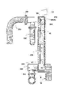
FIGURE ~ is a side elevation view partly in section of a
segment of a side-wall assembly in accordance with the present
invention, and
,

217~109
D-17285
FIGURE 5 is a side elevation view partly in section of a
spray cooled sub-assembly in accordance Wit~l the present
invention .

2~75~09
D-172~5
Detailed Description of the Invention
With reference to Figure 1, an electric arc furnace vessel
is indicated at 10, having a roof schematically illustrated at
12, and a side-wall assembly shown at 15 which surrounds
electrode 20. Peripheral hollow side-wall segments 22 (a) - (g),
shown also in the top, plan view of Figure 2, are arranged in a
side-by-side, i.e. lateral, abutting relationship, and are
supported on fLange 9 of arc furnace vessei 10. Each of the
hollow side-wall segments 22 (a) - (g), with reference to Figures 1
and 2, has respective illner metal base members 100 (a) - (g) shaped
to form a predetermined portion of the side-wall assembly. Outer
metal covering members 200 ~a) - (g) are spaced from and
respectively in register with the inner metal base members
100 (a) - (g) . With reierence to Figures 1-4, a substantially
enclosed space 300 is established for each side-wall segment
22 (a) - (g) by metal top plate 30, metal bottom plate 35, and metal
side plates 40, 42, which ~oin the outer covering members 200 (a) -
(g) to the inner base members 100 (a) - (g) . At the lowermost
portion 310 of each enclosed space 300 a drain opening 320 is
provided which communicates with drain outlet 330 and peripheral
coolant drain conduit 3a~0 adjacently exterior of and peripheral
to the side-wall segments 22 (a) - (g) . Liquid coolant supply
-- 4

21 7~1 Q9
'
D-17285
conduit 350 is removably connected at 355 tQ one of the
horizontally extending liquid coolant supply header conduits
400 (a) - (g) mounted at 410 within the respective hollow segments
22 (a) - (g) . A plurality of detachable conduits 500 are prQvided
exterior the hollow side-wall segments for connecting, in tandem,
the respective liquid coolant supply header conduit 400 in each
of the hollow segments 22 ~a) - (g) .
In operation, liquid coolant e.g. water, is delivered under
pressure from coolant supply conduit 350 to one of the liquid
supply header conduits 400; this particular header conduit being
designated as 400 ~A) . A plurality of hollow spray bars 600
extend transverse to and downwardly from header conduit 400 (A)
within hollow-segment 22 (b) to deliver coolant to spray nozzles
620 which are selected to deliver liquid droplets to the inner
metal base member lO0 (C) at a rate which cools the inner base
member 100 (C) to a desired lower temperature, with the coolant
remaining in liquid form and exiting enclosed space 300 through
drain opening 320 and passing through drain outlet 330 to coolant
drain conduit 340. CQQlant under pressure from coolant supply
conduit 350 passes from header conduit 400 (A) to each of the
other header conduits 400 (b) - (g) in the respective hollow
segments 22 (a) - (g) by way of detachable conduits 500 which
-- 5 --

` ~ 2 l 751 09
D-17285
conneGt the header conduits 400 in tandem to deliver coolant to
the hollow spray bars 600 and nozzles 620 in the respective
hollow side-wall segments 22 (a) - (g) . The hollow side-wall
segments 22(a)-(g) are adjacently engaged by removable fastening
means 660 which can be welded clamp elements. The spray bar and
nozzle configuration can be varied in each segment to accommodate
the thermal stress conditions to which the segment is exposed.
In a particular embodiment of the present invention, when a
particular location of the furnace slde-wall is subj ect to
particularly severe thermal stress, the side-wall segment at that
location, e.g. side-wall segment 22 (a), is formed in the shape of
an arch with an arch opening 700, within which a removable sub-
assembly 2200 is positioned. Sub-assembly 2200 is generally
similar in construction to the aforedescribed side-wall segments
and is supported on flange 9 of furnace vessel lO and has an
inner metal base member 1000 shaped to form that portion of the
side-wall assemoly which is subject to severe thermal stress. An
outer metal covering member 2000 is provided which is spaced from
and in register with inner metal base member 1000. An enclosed
space 3000 is established within sub-assembly 2200 by metal top
plate 3000, metal bottom plate 3500, and metal side plates 4000,
~200 which join the outer covering member 2000 to inner metal
-- 6 --

~175109
D-17285
base member 1000. At the lowermost portio~l 3100 of enclosed
space 3000 a drain opening 3200 is provided which communicate
with drain outlet 3300 (removably connected at 3150) and
peripheral coolant drain conduit 34D. A hori 7flnt~1 1 y extending
liquid coolant supply header 4000, mounted at 4100 within
enclosed space 3000, receives coolant under pressure ~rom coolant
supply header 400 of surrounding side-wall segment 22 (a) by way
of removably connected conduit 5000. The coolant received by
coolant supply header 4000 is delivered to hollow coolant spray
bars 6000 and nozzles 6200 in enclosed space 3000 which deliver
liquid droplets to inner metal base member 1000 at a rate which
cools the highly thermally stressed inner base member lO00 to a
desired lower temperature. The number and location of the spray
bars and nozzles is adjusted for the particular thermal stress
conditions to which the sub-assembly is exposed. Sub-assembly
2200 is removable from the side-wall by releasing fastening
elements 6~00 and removing releasable conduit 5000 and drain
3300. Thus, sub-assembly 2200 is readily serviceable and
repairable and is easily re-installed. Ceramic fiber insulation
7000 is suitably placed at all edges of the sub-assembly.
-- 7 --

Representative Drawing
A single figure which represents the drawing illustrating the invention.
Administrative Status

2024-08-01:As part of the Next Generation Patents (NGP) transition, the Canadian Patents Database (CPD) now contains a more detailed Event History, which replicates the Event Log of our new back-office solution.

Please note that "Inactive:" events refers to events no longer in use in our new back-office solution.

For a clearer understanding of the status of the application/patent presented on this page, the site Disclaimer , as well as the definitions for Patent , Event History , Maintenance Fee  and Payment History  should be consulted.

Event History

Description Date
Inactive: Expired (new Act pat) 2016-04-26
Inactive: IPC from MCD 2006-03-12
Letter Sent 2001-06-27
Inactive: Multiple transfers 2000-09-08
Grant by Issuance 1999-01-19
Inactive: Final fee received 1998-09-04
Pre-grant 1998-09-04
Letter Sent 1998-03-12
Notice of Allowance is Issued 1998-03-12
Inactive: Status info is complete as of Log entry date 1998-03-09
Inactive: Application prosecuted on TS as of Log entry date 1998-03-09
Inactive: Approved for allowance (AFA) 1998-02-11
Application Published (Open to Public Inspection) 1996-10-28
All Requirements for Examination Determined Compliant 1996-04-26
Request for Examination Requirements Determined Compliant 1996-04-26

Abandonment History

There is no abandonment history.

Maintenance Fee

The last payment was received on 1998-04-14

Note : If the full payment has not been received on or before the date indicated, a further fee may be required which may be one of the following

  • the reinstatement fee;
  • the late payment fee; or
  • additional fee to reverse deemed expiry.

Please refer to the CIPO Patent Fees web page to see all current fee amounts.

Owners on Record

Note: Records showing the ownership history in alphabetical order.

Current Owners on Record
SOUTH CAROLINA SYSTEMS, INC.
Past Owners on Record
DAVID ARTHUR LEHR
FRANK HENRY MINER
GORDON RAYMOND ROBERTS
MARK THOMAS ARTHUR
WILLIAM HOWARD BURWELL
Past Owners that do not appear in the "Owners on Record" listing will appear in other documentation within the application.
Documents

To view selected files, please enter reCAPTCHA code :


To view images, click a link in the Document Description column. To download the documents, select one or more checkboxes in the first column and then click the "Download Selected in PDF format (Zip Archive)" or the "Download Selected as Single PDF" button.

List of published and non-published patent-specific documents on the CPD .

If you have any difficulty accessing content, you can call the Client Service Centre at 1-866-997-1936 or send them an e-mail at CIPO Client Service Centre.


Document
Description 
Date
(yyyy-mm-dd) 
Number of pages   Size of Image (KB) 
Description 1996-08-12 7 200
Drawings 1996-08-12 5 132
Cover Page 1996-08-12 1 19
Claims 1996-08-12 9 255
Abstract 1996-08-12 1 9
Cover Page 1999-01-07 1 40
Representative drawing 1999-01-07 1 9
Reminder of maintenance fee due 1997-12-30 1 111
Commissioner's Notice - Application Found Allowable 1998-03-12 1 165
Correspondence 2000-10-20 1 9
Correspondence 1998-09-04 1 52
Correspondence 2000-10-16 1 6
Prosecution correspondence 1996-04-26 1 82