Note: Descriptions are shown in the official language in which they were submitted.
21'~~123
1
REFRIGERATION COMPRESSOR THRUST BEARING ASSEMBLY
The present invention relates generally to
hermetic refrigeration compressors and especially
low capacity refrigeration compressors used in
household appliances. More particularly, the
invention relates to thrust bearing assemblies for
supporting vertical rotor and crankshaft
combinations commonly associated with
refrigeration compressors. An area of concern
long associated with such compressors, as well as
other machines, is the amount of mechanical
friction that occurs within the compressor during
operation. Compressor efficiency is quantified as
an energy efficiency ratio (EER), which is derived
by dividing the compressor output in BTU/hour by
the power consumed by the compressor under
standard operating conditions. According to this
relationship, it becomes apparent that one way of
increasing the efficiency of a compressor is to
decrease the amount of power consumed by the
compressor without adversely affecting its BTU
output.
One source of power consumption within the
compressor is the mechanical friction between the
bearing frame hub and the rotating rotor and
crankshaft combination. Many types of thrust
bearings have been used to diminish mechanical
friction and thereby reduce the power consumed by
a compressor. Thrust bearings of the past have
been machined steel, plain or oil film type,
mufti-layered, a composite of materials, or a ball
bearing assembly to name a few. Problems
associated with prior art thrust bearings include
the following~ warpage of copper and copper alloy
bearings; expense associated with metallic, alloy
materials, mufti-layered bearings, and ball
21~~:~2~
2
bearing assemblies; and complexities in
manufacturing associated with ball bearing
assemblies.
In particular, ball bearing type thrust
bearings employ a pair of flat thrust washers
which serve as races between which balls are
mounted in a plastic cage. In general, ball type
bearings require a lower starting torque than the
fluid film type bearings. However, once running
under hydrodynamic film, the fluid film type
bearings exhibit friction characteristics
comparable to those of ball type bearings.
One of the disadvantages of the ball type
bearing is the necessity to use through-hardened
~ acid-corrosion resistant metal for the rolling
elements and flat thrust washers. The plastic
material used for fabricating the bearings cage is
sensitive to temperature and has a lower
continuous service temperature than the metal
balls and thrust washers.
Another disadvantage is the requirement for
multiple parts (balls, cage, bearing, and two
washers) which increases production costs and
results in additional frictional pairs. In
addition, ball type bearings produce greater noise
than fluid film type bearings.
According to the present invention, the
mechanical friction associated with a vertical
rotor and crankshaft combination as it rests upon
and rotates about the frame bearing hub is reduced
both at startup and during compressor operation by
utilizing a thrust bearing formed of a polyamide
material. By pressfitting the thrust bearing
within the counterbore formed in the rotor,
rotation of the thrust bearing relative to the
rotor is prevented. This results in rotational
21'~~123
3
contact between a single frictional pair, the
lower surface of the thrust bearing against the
upper end face of the bearing hub, thereby
reducing the amount of mechanical friction within
the compressor. By reducing the friction caused
by the radial reaction of the crankshaft at
compressor startup and during operation, the
present invention increases overall compressor
ef f is iency .
The polyamide material used to form the
thrust bearing of the present invention is
characterized by a very low coefficient of static
and kinetic friction. This results in reduced
mechanical friction and reduced power consumption
associated with starting and operating the
compressor. Another beneficial characteristic
associated with polyamide is its broad temperature
range thermal stability. Even unlubricated
polyamide thrust bearings are capable of ,
withstanding approximately 300,000 lb.ft./in. min.
with a maximum contact temperature of 740°F.
Lubricating oil is delivered by the crankshaft to
the thrust bearing surface, thereby further
reducing the coefficient of friction during
compressor operation. Properly lubricated
polyamide thrust bearings can withstand
approximately 1 million KPSI feet/minute. A
plurality of radially extending grooves are
provided in the thrust bearing surface, thereby
enhancing the delivery of lubricating oil to the
bearing/hub contact area.
In the preferred embodiment, the end face of
the bearing hub is machine ground to a smooth
finish and a fine polishing operation is applied,
thereby further reducing the coefficient of
friction between the hub and the thrust bearing
CA 02175123 2000-07-12
4
surface. While the surface finish is not critical, it does have an effect on
performance.
The smoother the surface, the better the performance.
Therefore, one advantage of the present invention is a reduction in the
coefficients of static and kinetic friction associated with the compressor
thrust
bearing, which results in reduced power consumption and increased overall
compressor efficiency.
Another advantage of the present invention is a reduction in the costs
associated with traditional bearing assemblies by using a pressfit
installation and
single piece construction of the polyamide thrust bearing.
1o Yet additional advantages of the present invention are: vibration
dampening, lack of corrosion, broad temperature range thermal stability, and
superior
chemical and abrasion resistance.
In one aspect, the present invention provides a refrigeration compressor
comprising:
15 a housing;
a frame comprising a bearing hub, said bearing hub defining a first
vertical bore and having an upper end face, said frame mounted within said
housing;
a motor comprising a stator and a rotor, said rotor defining a second bore
and a countersunk recess;
2o a crankshaft received in said recess and secured to said rotor, said
crankshaft disposed in said first vertical bore;
a pump unit driven by said crankshaft; and
an annular thrust bearing press-fit in said recess and fixed relative to said
rotor, said thrust bearing comprising a lower annular bearing surface engaging
said hub
25 upper end face so as to form a single frictional of surfaces pair between
said rotor, said
thrust bearing, and said bearing hub.
In another aspect, the present invention provides in a refrigeration
compressor comprising a motor having a stator and a rotor, a frame having a
bearing
hub, and a vertical crankshaft, said rotor comprising an inner aperture which
receives
3o said vertical crankshaft and a countersunk recess having an inner wall,
said vertical
CA 02175123 2000-07-12
crankshaft being secured to said rotor and disposed in said bearing hub, said
hub having
an upper end face, an annular thrust bearing comprising:
an annular lower bearing surface and an annular upper bearing surface,
said lower bearing surface and said hub upper end face engaging one another so
as to
form a single frictional pair of surfaces between said rotor, said thrust
bearing, and said
bearing hub; and
an exterior annular wall extending perpendicularly from said lower
bearing surface to said upper bearing surface, said thrust bearing being press-
fit in said
recess whereby said thrust bearing exterior annular wall engages said recess
inner wall
l0 so as to prohibit rotational movement of said thrust bearing relative to
said rotor.
In the preferred embodiment, the polyamide thrust bearing is formed of
Torlon* as produced by Amoco or Vespel* as produced by DuPont. The PV limits,
defined as the product of load or pressure (P) and sliding velocity (V),
associated with
the unlubricated Vespel* bearing material under continuous motion is 300,000
lb.ft./in
15 min. with a maximum contact temperature of 740°F (393°C)
vastly exceeding the limits
of unfilled nylon.
The above-mentioned and other features and objects of this invention,
and the manner of attaining them, will become more apparent and the invention
itself
will be better understood by reference to the following description of an
embodiment of
2o the invention taken in conjunction with the accompanying drawings, wherein:
Fig. 1 is a cross-sectional view of one embodiment of the refrigeration
compressor of the present invention;
Fig. 2 is a bottom view of the thrust bearing for use in the compressor of
the present invention;
25 Fig. 3 is an enlarged fragmentary side view of the thrust bearing of Fig. 2
showing a
* Trade Mark
CA 02175123 2000-07-12
6
lubricating oiled groove formed therein viewed in the direction of arrows 3-3
in Fig.
2;
Fig. 4 is a cross-sectional view of the thrust bearing of Fig. 2;
Fig. 5 is a partial cross-sectional view showing the crankshaft, rotor,
bearing hub, and thrust bearing of the refrigeration compressor of Fig. 1; and
Fig. 6 is a cross-sectional view of a second embodiment of the
compressor of the present invention.
1o Corresponding reference characters indicate corresponding parts
throughout the several views. The exemplifications set out herein illustrate a
preferred embodiment of the invention, in one form, and such exemplifications
are not
to be construed as limiting the scope of the invention in any manner.
Referring now to the drawings and particularly to Fig. 1, reciprocating
15 compressor 20 is shown in one embodiment which is only provided as an
example of
a type of compressor in which the present invention thrust bearing may be
implemented. As the thrust bearing of the present invention may be utilized in
numerous and varied compressor configurations, the invention is not limited to
the
compressor illustrated in Fig. 1.
20 U.S. Patent No. 5,160,247, issued to the assignee of the present
invention provides a detailed description of the operation of a refrigeration
compressor which is compatible with the present invention.
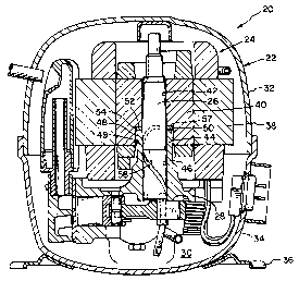
Refrigeration compressor 20 generally includes housing or shell 22,
motor 24, crankshaft 26, frame and oil sump 30. Housing 22 consists
7
of upper housing portion 32 and lower housing
portion 34 which are hermetically secured to one
another by welding or brazing. Mounting flange 36
is welded to the bottom of lower housing portion
34 for mounting the compressor in a stable
position. Motor 24 consists of stator 38, which
is secured to frame 28, and rotor 40, which is
provided with bore 42 into which is secured
crankshaft 26 by means of an interference fit.
The weight of the rotor and crankshaft combination
is generally supported by frame 28. Extending
upwards from frame 28 is bearing hub 44, the
center of which defines vertical bearing bore 46.
Crankshaft 26 is journalled for rotation within
~ vertical bearing bore 46. Countersunk recess 48
is provided in the lower portion of rotor 40 so
that the rotor is disposed about bearing hub 44
with crankshaft 26 journalled in vertical bearing
bore 46. The weight of the rotor and crankshaft
combination is born directly by bearing hub 44 at
upper end face 50.
Thrust bearing device 52 is formed of a
polyamide material such as Torlon as manufactured
by Amoco or Vespel as manufactured by DuPont.
Thrust bearing 52 consists of lower surface 54,
outer annular wall 55, grooved channels 56, and
upper surface 57. Smooth lower surface 54 is
characterized by low coefficients of static and
kinetic friction. Grooved channels 56 extend
radially across lower surface 54 and communicate
oil to lubricate lower surface 54 and hub upper
end face 50. Figs. 2 and 4 illustrate thrust
bearing 52 in one particular embodiment in which
there are three grooves 56 which are equally
radially spaced 120° apart on lower surface 54.
The invention is not limited to this configuration
2~~~123
8
and extends to permutations thereof. Grooves 56
serve to communicate lubricating oil to the
contact surface between lower surface 54 and upper
end face 50. While Fig. 3 illustrates grooves 56
as having a curved shape, the scope of the
invention is not limited to a particular shape and
extends to include any shape and configuration
that will adequately supply lubricating oil to the
contact surface. With particular reference to
Fig. 5, outer annular wall 55 extends vertically
from the outer perimeter of lower surface 54 and
upper surface 57 and, upon being pressfit in
aperture 48 of rotor 40, engages inner wall 49 so
as to prevent rotational movement of thrust
bearing 52 relative to rotor 40. As shown in Fig.
5, lubricating oil is delivered to grooved
channels 56 by cam shaft spiral groove 58 which
communicates oil collected in oil sump 30. In
this manner, mechanical friction occurring during
compressor operation is reduced.
By pressfitting thrust bearing 52 into
aperture 48 of rotor 40 and preventing the
rotation of thrust bearing 52 relative to rotor
40, only one frictional pair, that of lower
surface 54 against hub upper end face 50, will
incur rotational sliding contact. In a preferred
embodiment, hub upper end face 50 is machine
ground to a smooth surface, this is preferable
over a turned surface. Hub upper end 50 may be
3o finely polished for additional smoothness and
lower surface 54 of thrust bearing 52 may be
manufactured having a finish of 20 microinches.
In this manner the mechanical friction associated
with compressor startup and operation is reduced,
thereby increasing overall compressor operating
efficiency.
21'~~12~
9
Fig. 6 illustrates the present invention in a
second embodiment in which thrust bearing 52 is
utilized in rotary type compressor 20'. Thrust
bearing 52 is configured as shown in Figs. 2, 3,
and 4 and as described above. Bearing 52 is
pressfit into aperture 48' such that bearing outer
annular wall 55 engages with rotor inner wall 49',
thereby preventing the rotation of the bearing
relative to rotor 40'. Accordingly, only one
frictional pair, that of lower surface 54 against
hub upper end face 50', will incur rotational
sliding contact.
While this invention has been described as
having a preferred design, the present invention
can be further modified within the spirit and
scope of this disclosure. This application is
therefore intended to cover any variations, uses,
or adaptations of the invention using its general
principles. Further, this application is intended
to cover such departures from the present
disclosure as come within known or customary
practice in the art to which this invention
pertains and which fall within the limits of the
appended claims.