Language selection

Search

Patent 2175468 Summary

Third-party information liability

Some of the information on this Web page has been provided by external sources. The Government of Canada is not responsible for the accuracy, reliability or currency of the information supplied by external sources. Users wishing to rely upon this information should consult directly with the source of the information. Content provided by external sources is not subject to official languages, privacy and accessibility requirements.

Claims and Abstract availability

Any discrepancies in the text and image of the Claims and Abstract are due to differing posting times. Text of the Claims and Abstract are posted:

  • At the time the application is open to public inspection;
  • At the time of issue of the patent (grant).
(12) Patent Application: (11) CA 2175468
(54) English Title: SKATE HEEL BINDING
(54) French Title: DISPOSITIF DE FIXATION D'UN PATIN A GLACE AU TALON D'UNE BOTTINE DE PATINAGE
Status: Deemed Abandoned and Beyond the Period of Reinstatement - Pending Response to Notice of Disregarded Communication
Bibliographic Data
(51) International Patent Classification (IPC):
  • A63C 1/10 (2006.01)
  • A63C 1/04 (2006.01)
  • A63C 9/084 (2012.01)
(72) Inventors :
  • JOHANSSON, BENGT (Sweden)
(73) Owners :
  • HARALD ALMGREN AB
(71) Applicants :
(74) Agent: NORTON ROSE FULBRIGHT CANADA LLP/S.E.N.C.R.L., S.R.L.
(74) Associate agent:
(45) Issued:
(86) PCT Filing Date: 1994-10-31
(87) Open to Public Inspection: 1995-05-11
Availability of licence: N/A
Dedicated to the Public: N/A
(25) Language of filing: English

Patent Cooperation Treaty (PCT): Yes
(86) PCT Filing Number: PCT/SE1994/001020
(87) International Publication Number: WO 1995012439
(85) National Entry: 1996-04-30

(30) Application Priority Data:
Application No. Country/Territory Date
9303581-4 (Sweden) 1993-11-01

Abstracts

English Abstract


The present invention relates to a heel binding
(10) for a skate (12) and comprises a heel lock mech-
anism with a vertically pivotable locking member (20),
arranged, in an actuated position, to be in contact with
an edge portion of the top of the heel (34) of a skater's
boot, and in a non-actuated position to be pivoted back-
wards away from the heel. The locking mechanism (20)
is bifurcated and has a lower linkage arm (26) actuated
by the heel and an upper locking arm (24) fixing the
heel. An operating arm (36) is vertically pivotable adja-
cent the locking member (20) and supports a cam roller
(38), which is resiliently biassed against a cam profile
(44) on the rear edge of the locking arm, by means of
a spring (42).


French Abstract

L'invention porte sur un dispositif de fixation (10) d'un patin à glace (12) au talon d'une bottine, comprenant un mécanisme de verrouillage muni d'un élément de verrouillage pivotant verticalement (20) et conçu pour se trouver, en position d'accouplement, en contact avec une partie marginale supérieure du talon (34) de la bottine du patineur, et en position libérée, basculé en arrière de façon à s'écarter du talon. Le mécanisme de verrouillage (20) en forme de fourche présente un bras de liaison inférieur (26) actionné par le talon et un bras supérieur de verrouillage (24) fixant le talon. Un bras d'actionnement (36) pivote de façon à venir en contact avec l'élément de verrouillage (20), ce bras étant muni d'un galet de came (38) sollicité par un ressort (42) sur un profil de came (44) situé sur le bord arrière du bras de verrouillage.

Claims

Note: Claims are shown in the official language in which they were submitted.

1. Heel binding (10) for a skate (12), comprising a lateral
support (58) for the heel (34) of a skater's boat and a heel
lock mechanism for vertically fixing the heel (34) on the
skate (12), said heel lock mechanism comprising a bracket
(14) mounted on the rear portion of the skate (12), in which
a locking member is vertically pivotable and is adapted in an
actuated position to be in contact with an edge portion of
the top of the heel and in an unactuated position to be
pivoted backwards away from the heel, said locking member
(20) being a bifurcated locking member which has a lower arm
(26) actuatable by the heel (34) of the skater's boot and an
upper heel fixing arm (24) provided with a jaw (28), a
pivoted operating arm (36) belng disposed to be resiliently
pressed against a cam profile (44) on the rear edge of the
locking member (20) by a spring means (42), characterized in
that the operating arm (36) is pressed against a cam profile
(44) via a cam roller (38), said spring means (42) consisting
of a tensile spring (42) and being fixed to the locking
member (20) and disposed to be tensioned by the cam roller
(38) when the operating arm (36) is moved backwards, away
from the locking member (20) to pivot said locking member
away from its actuated position to its heel releasing
position.
2. Heel binding according to Claim 1, characterized in that
the operating arm (36) is disposed to overlap or enclose a
substantial portion of the locking member (20) in its
actuated position.
3. Heel binding according to Claim 1 or 2, characterized in
that the cam profile (44) has two depressions (45,48) serving
as end positions for the cam roller (8) and separated from
each other via a cam crest (50).
4. Heel binding according to one of Claims 1-3, characterised
in that the lower and upper arms of the locking member (20)
have the shape o a linkage arm (26) and a locking arm (24),

respectively, which are limitedly pivotal relative to each
other via a common pivot pin (22).
5 . Heel binding according to one of claims 1-4, characterized
in that the locking member (20) and the operating arm (36)
are pivotally mounted in the same bracket (14) on pivot pins
(22 and 37, respectively) lying in the same vertical plane or
in closely adjacent vertical planes.
6. Heel binding according to one of Claims 1-5, characterized
in that the bracket (14) has the shape of a bottom plate (16)
with two postlike lateral supports (18) extending upwards
from a bottom plate (16), said supports receiving between
them portions of the locking member (20) and the operating
arm (36).
7. Heel binding according to one of Claims 1-6, characterized
in that the heel lateral support means (58) is in the form of
two arms (60,62), each having a distal end with an upright
support (64) for contact with the side of the skater's boot
heel (34) and a proximal end which is adjustably fixed in the
rear portion of the skate (12), preferably together with the
bracket (14).

Description

Note: Descriptions are shown in the official language in which they were submitted.


2 ~ 75~68
WO 95/12439 PCT/SI 94/01020
SK2lte Heel Billaillg
The present invention relates to a heel bindins for a 6kate
comprising a lateral support for the heel of a skater's boot
and a heel lock mechanism for vertically fixing the heel on
the skate, said heel lock rn~-~h~n; F:m comprising a bracket
mounted on the rear portion of the skate, in which a locking
member is vertically pivotable and is adapted, in an actuated
position, to be in contact with an edge portion on the top of
the heel, and in an unactuated position, to be pivoted
backwards away f rom the heel, said locking member being a
bifurcated locking member which has a lower arm actuatable by
the heel of the skater's boot and an upper heel fixing arm
provided with a jaw, a pivoted operating arm 36 being
disposed to be resiliently pressed against a cam profile on
the rear edge of the locking member by a spring means.
Previously known heel bindings for bootless skates have
required manual manipulation to lock and unlock the heel
binding, and said manipulation 15 time-cons,uming and
dif~icult for many skaters
Heel bindings for skis have been previously suggested (cf for
example IJS-A-3 325 178 ), which make possible automatic
locking of the heel portion of a ski boot and a simplified
release and opening of the binding. However, such ski
bindings are not suited for use on skates, since they are
relatively long in the longitudinal direction, thus making it
impossible to bind the boot heel near the rear end of the
skate .
One purpose of the present illvention has been to achieve a
new, improved heel binding for skates, which makes it
~ossible to lock automatically the heel portion of the
skater's boot to the skate, and to make possible a simplified
onlocking or opening of the heel binding. At the same time
the heel binding should have a very compact design, i . e . it
should extend a very small distance in the longitudinal
direction of the skate, so that the binding can be m~unted at
-

Wo 95/12439 2 1 7 5 4 ~ 8 PCT/S3~94/01020
the very rear enà of the s3sate.
In order to solve this problem, a binding of the type
described by way of introduction is characterized according
to the invention in that the operating arm is pressed against
the cam profile via a cam roller, said spring means
consisting of a tensile spring which is fixed to the locking
member and is disposed to be tensioned by the cam roller when
the operating arm is moved backwards, away from the locking
member to pivot said locking member away from its heel
releasing position. Such a design makes it possible to mount
an automatically locking and easily opened binding with
compact external dimensions at the rear end of the skate.
Additional details and features of the binding according to
the invention are disclosed in the subclaims and will be
described in more detail below with reference to the
accompanying drawing, in which:
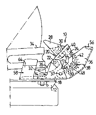
Fig 1 is a sideview of a heel binding according to the
invention in its opened position;
Fig 2 shows the binding in its boot heel locking position;
and
Fig 3 is a view from above of the binding according to
the invention.
The heel binding, generally designated 10, according to the
present invention, comprises a bracket 14 mounted on the top
of the rear end of the bootless skate 12. The bracket has a
bottom plate 16 and two parallel, s~aced lateral supports 18,
which extend vertically upwards. The lateral supports 18
provide a mount for a bifurcated locking member 20, which is
journalled in the supports 18 by means of a pin 22. The
locking member 20 consists of an upper locking arm 24 and a t
lower linkage arm 26. The upper locking arm 24 has at its
front a jaw 28, which is vertically adjustable along a
grooved portion of the front of ~the locking arm 24 and can be
fixed in place by means of a screw 30. The lower linkage arm
26 has a forwardly directed end portion 32 designed, during

21 7546
WO 9~1?~739 8 ~ o7~l?n
locking of the binding 10 to be pressed down by the rear
portion of the heel 34 of the skater' s boot . When the binding
i8 opened, it is designed to lift the heel 34 upwards. The
two arms of the locking member 20, i.e. the linkage arm 26
and the locking arm 24, can be limitedly pivotable relative
to each other about the pin 22 in order to provide, when the
binding lO is being locked, a certain delay in the closing of
the locking arm 24 against the heel 34 relative to the pivot
movement of the linkage arm 26, and a preceding pushing back
of the locking arm 24 when the binding is being opened.
An operating arm 3 6 is pivotably mounted on the bracket 14
via a pivot pin 37, which is mounted in the lower portion of
the supports 18 and close to the pin 22 in the longitudinal
direction of the skate. In the embodiment shown, the
operating arm 36 has a U-profile cross section, so that it
can receive and enclose the maj or portion of the locking
member 20 between the lateral sides of the U-profile when the
binding is in its locked position.
The operating arm 36 supports at its center portion a cam
roller 3 8, which extends between the lateral sides of the U-
prof ile and is rotatably mounted therein . A tensile spring 42
fixed in the upper portion of the locking arm 24 at 40
extends behind the cam roller 38 and is fixed at its other
end to the pivot pin 37 of the operating arm 36. The tensile
spring 42 thus exerts a resilient force on the cam roller 38
so that it will be held in contact with a cam surface 44 on
the rear edge of the locking arm 24. The cam surface 44 has
two depressions 46 and 48, serving as end positions for the
cam roller 38. In the opened position of the binding 10 shown
in Fig 1, the cam roller 3 8 rests in the upper end position
48, while, in the closed position of the binding as shown in
Fig 2, the cam roller 38 has passed a cam stop 50 and has
jumped into the lower end position 46.
Fig 2 shows a safety catch (not shown in Figs 1 and 3), which
has the shape of a pawl 52, which is spring-biassed towards
its locking position shown in Fig 2, where it engages over

WO 95ll2439 2 ~ ~ ~ 4 ~ ~ PCr/SE94/0l020
the upper edge of the locking arm 24 and prevents the
operating arm 36 from being pivoted backwards and thus
unintentionally opening the binding 10, unless the rear end
54 of the pawl 52 is pushed down to release the operating arm
s 36. The upper end of the operating arm 36 has a depression
56, in which the point of a skater's icepike can be placed to r
push down the operating arm 3 6 .
The binding 10 also has a lateral support 58 for the heel 34,
which in the embodiment shown consists of two arms 60 and 62
(Fig 3), the inner ends of which are fixed together with the
bracket 14 to the skate 12. The obliquely forwardly-outwardly
directed distal end of each arm has an upwardly directed
support 64 with a slightly flared upper portion to facilitate
insertion of the heel 34 between the supports 64. The
position of the arms 60, 62 in the horisontal plane is
adjustable to adapt the lateral support means 53 to diiferent
heel sizes. The lateral support means 58 for the heel 34 can
conceivably be made, in another embodiment (not shown)
integral with the bracket or another portion of the binding
10 .
The binding 10 functions in the following manner:
The toe of the boot is first inserted i~to a front toe
support of known design (not shown in the drawing). The heel
34 is then pushed down between the lateral supports 64 of the
lateral support means 58. The heel thereby presses the
linkage arm 26 downwards over its end portion 32, thus
pivoting the upper locking arm 34 forwards, i.e. counter
clockwise in Fig 1, about the pin 22. At the same time the
cam roller 38 leaves its upper end position 48 passing over
the cam crest ~0, whereupon the cam roller 38, biassed by the
spring 42 jumps into the lower end position depression 46,
thus pressing the j~w 28 down against the upper edge of the
heel 34. If the operating arm 36 has a pawl 52, as shown in
Fig 2, the point of the pawl 52 will snap into the position
engaging the frontside of the locking arm 24, thus preventing
the operating arm 36 from pivoting clockwise.
. _ _ _ _ . . . . . .. _ . . _ .. _ . .

WO95/124f39 2 1 ~ 8 PClr~Sl~94101020
In order to open the binding lo, the operating arm 36 if
pressed backwards, either by hand or with an icepike in the
depression 56, preceded by release of the pawl 56, i~
present. When the cam roller 38 has passed the cam crest 50,
the locking arm 24 is pivoted outwards until the cam roller
38 reaches its upper end position 48, as shown in Fig 1,
whereupon the link~ge arm 26, which is slightly pivotable
relative to the locking arm 24, permits the locking arm 24
with the jaw 28 to be opened somewhat be~ore the linkage arm
26 presses the heel 34 up and out of the binding.
f ' .: . `, . j

Representative Drawing
A single figure which represents the drawing illustrating the invention.
Administrative Status

2024-08-01:As part of the Next Generation Patents (NGP) transition, the Canadian Patents Database (CPD) now contains a more detailed Event History, which replicates the Event Log of our new back-office solution.

Please note that "Inactive:" events refers to events no longer in use in our new back-office solution.

For a clearer understanding of the status of the application/patent presented on this page, the site Disclaimer , as well as the definitions for Patent , Event History , Maintenance Fee  and Payment History  should be consulted.

Event History

Description Date
Inactive: IPC assigned 2022-10-18
Inactive: IPC expired 2012-01-01
Inactive: IPC from MCD 2006-03-12
Application Not Reinstated by Deadline 2002-10-31
Time Limit for Reversal Expired 2002-10-31
Inactive: Abandon-RFE+Late fee unpaid-Correspondence sent 2001-10-31
Deemed Abandoned - Failure to Respond to Maintenance Fee Notice 2001-10-31
Application Published (Open to Public Inspection) 1995-05-11

Abandonment History

Abandonment Date Reason Reinstatement Date
2001-10-31

Maintenance Fee

The last payment was received on 

Note : If the full payment has not been received on or before the date indicated, a further fee may be required which may be one of the following

  • the reinstatement fee;
  • the late payment fee; or
  • additional fee to reverse deemed expiry.

Please refer to the CIPO Patent Fees web page to see all current fee amounts.

Fee History

Fee Type Anniversary Year Due Date Paid Date
MF (application, 3rd anniv.) - small 03 1997-10-31 1997-10-09
MF (application, 4th anniv.) - small 04 1998-11-02 1998-10-27
MF (application, 5th anniv.) - small 05 1999-11-01 1999-10-25
MF (application, 6th anniv.) - small 06 2000-10-31 2000-10-17
MF (application, 2nd anniv.) - small 02 1996-10-31
Owners on Record

Note: Records showing the ownership history in alphabetical order.

Current Owners on Record
HARALD ALMGREN AB
Past Owners on Record
BENGT JOHANSSON
Past Owners that do not appear in the "Owners on Record" listing will appear in other documentation within the application.
Documents

To view selected files, please enter reCAPTCHA code :


To view images, click a link in the Document Description column. To download the documents, select one or more checkboxes in the first column and then click the "Download Selected in PDF format (Zip Archive)" or the "Download Selected as Single PDF" button.

List of published and non-published patent-specific documents on the CPD .

If you have any difficulty accessing content, you can call the Client Service Centre at 1-866-997-1936 or send them an e-mail at CIPO Client Service Centre.


Document
Description 
Date
(yyyy-mm-dd) 
Number of pages   Size of Image (KB) 
Representative drawing 1997-06-17 1 10
Cover Page 1996-08-08 1 14
Abstract 1995-05-11 1 48
Description 1995-05-11 5 213
Claims 1995-05-11 2 83
Drawings 1995-05-11 1 25
Reminder - Request for Examination 2001-07-04 1 118
Courtesy - Abandonment Letter (Maintenance Fee) 2001-11-28 1 183
Courtesy - Abandonment Letter (Request for Examination) 2001-12-12 1 171
Fees 1996-04-30 1 44