Note: Descriptions are shown in the official language in which they were submitted.
2~ 75~43
-
PTC DEVICE
BACKGROUND OF THE I~v~NllON
This application relates to the art of
thermal protectors and, more particularly, to
thermal protectors that employ a PTC material. The
invention is particularly applicable for use in
protecting electric motors and will be described
with specific reference thereto. However, it will
be appreciated that the invention has broader
aspects and can be used for protecting electrical
devices other than motors.
Small electric motors used in such
applications as power windows and power seats in
lS automobiles are commonly protected against overload
by an electro-mechanical thermal protector. When a
device operated by the motor stalls, the motor
remains connected to a battery voltage source and
the heat produced causes operation of an electro-
mechAnical thermal protector that disconnects themotor from the battery voltage source. When the
thermal protector cools down, the motor will again
be connected to the voltage source. If the problem
has not been corrected, the electro-merhAnical
thermal protector will cycle on and off until the
battery is completely drained.
PTC devices switch to a very high
resistance state at a predetermined elevated
temperature and a trickle current that continues to
flow through the PTC material produces sufficient
heat for maintaining the PTC device in its high
resistance switched condition. The trickle current
CLLITOI Doc: 12979~ 1
` 21 75~43
.
will not rapidly discharge the battery because the
current used is comparable to that used for an
automobile clock. The PTC device will not reconnect
the motor to the battery until the problem has been
corrected. Replacing electro-me~h~nical thermal
protectors with PTC protectors is difficult and
PYrP~ive because the electro-mechAnical protectors
are significantly larger than the PTC devices.
Therefore, the PTC devices will not normally fit
within a holder for an electro-mech~nical thermal
protector and a complete redesign of the holder
would be necPcs~ry.
It would be desirable to have the
capability of replacing electro-mechanical thermal
protectors with PTC protectors without completely
re-designing an entire holder in which the thermal
protector is held.
SUMMARY OF THE INVENTION
A plastic motor brush holder includes a
pocket for closely receiving an electro-mechanical
thermal protector. One well-known type of electro-
merh~n;cal thermal protector is sold under the brand
name "Otter". In accordance with the present
application, a PTC device is provided with an
increased effective thickness for close reception
within a pocket that is sized for normally closely
receiving an electro-mechanical thermal protector.
In accordance with one arrangement, the
PTC device of the present application includes a
central layer of PTC material that may be a carbon
filled polymer. The material has a positive
CLLITOl Doc. 12~795 1
` 2175~43
temperature coefficient of resistance so that there
is normally very little resistance to current flow.
At a predetermined elevated temperature, the PTC
material automatically switches to its high
resistance state in which only a very small trickle
current will continue to flow. The trickle current
is insufficient to damage the motor but is adequate
to produce sufficient heat in the PTC material for
maintaining it in its high resistance state until
the problem is corrected.
The flat layer of PTC material has metal
foil laminated to its opposite faces and the foil is
soldered to a pair of opposite outer metal plates.
Thus, the PTC material is sandwiched between a pair
of metal plates.
The metal plates have top and bottom edges
and opposite sides. Terminals extend downwardly
from the bottom edges of the metal plates for
connecting the PTC device in a circuit.
Flanges extend outwardly from edges of at
least one of the plates for increasing the effective
thickness of the PTC device. A top flange on at
least one of the plates cooperates with a retainer
in a pocket for holding the PTC device in the
pocket.
Instead of providing flanges to increase
the effective thic~necs, it will be recognized that
it is possible to provide a layer of dielectric
material over the metal plates for increasing the
overall thic~n~c~ of the PTC device.
It is a principal object of the present
invention to provide an improved PTC device that can
CLLrr~l Doc. 12979S_I
2 1 75~43
.
--4--
be used for replacing electro-mec~Anical thermal
protectors.
It is also an object of the present
invention to provide a PTC device with an increased
effective thickness by forming outwardly exte~ing
flanges on the PTC device.
BRIEF DESCRIPTION OF THE DRAWING
Figure 1 is a top plan view of a motor
brush holder having the PTC device of the present
application positioned therein;
Figure 2 is a partial cross-sectional
elevational view taken generally on line 2-2 of
figure l;
Figure 3 is a partial cross-sectional
elevational view taken generally on line 3-3 of
figure 1;
Figure 4 is a front elevational view of a
PTC device constructed in accordance with the
present application;
Figure 5 is a side elevational view
thereof;
Figure 6 is a perspective illustration of
another embodiment;
Figure 7 is a perspective illustration of
still another embodiment;
Figure 8 is a perspective illustration of
still another embodiment;
Figure 9 is a perspective illustration of
still another embodiment;
Figure 10 is a perspective illustration of
still another embodiment;
CL~TOl Do 129795_1
" ` 21 75~43
-
Figure 11 is a side elevational view of
still another embodiment;
Figure lla is a partial cross-sectional
elevational view similar to Figure 3 and showing the
PTC embodiment of Figure 11 received in a pocket;
Figure 12 is a perspective illustration of
still another embodiment; and
Figure 13 is a side elevational view of
the PTC device of Figure 12.
DESCRIPTION OF PREFERRED EMBODIMENTS
Referring now to the drawing, wherein the
showings are for purposes of illustrating certain
preferred embodiments of the invention only and not
for purposes of limiting same, Figure 1 shows a
molded plastic motor brush holder having a central
circular opening 10 for surrounding an unshown motor
armature. Motor brushes 12,14 received in guides
16,18 are biased by springs 20,22 toward the center
of opening 10 into engagement with the motor
armature.
Motor brush 14 has a lead 24 connected
with a plug-in terminal member 26. Another plug-in
terminal member 28 extends past motor brush 12
toward PTC device B and includes a horizontal
portion 30 that is supported in a recess in a
support 32 located adjacent PTC device B.
Horizontal portion 30 of terminal member 28 has an
unshown downwardly extending terminal portion that
is soldered to a terminal on PTC device B. The
other terminal on PTC device B is soldered to a
CLIITOl D~ 12~79S 1
`` 2175~43
connecting wire 34 that is attached to lead 36 of
motor brush 12.
Motor brush holder A is provided with a
pocket for receiving a thermal protector. Pocket
opposite sides 40,42 are defined on upst~n~;ng
projections or side walls 44,46. Front and rear
pocket surfaces 50,52 are defined between support
wall 32 and an outer or rear wall 54.
The pocket for receiving the thermal
protector is generally indicated by numeral 60 in
Figure 3 and includes top and bottom openings 62,64.
An inwardly extPn~ing projection 66 on a resilient
finger 68 provides a tab for retaining a thermal
protector within pocket 60. Resilient finger 68 is
shown in Figure 2 and can be deformed outwardly to
displace tab 66 and increase the size of top opening
62 for insertion of a thermal protector within
pocket 60. Releasing finger 68 then moves tab 66
back to the position shown in Figure 3 partially
closing top opening 62 and partly overlying the top
end of a thermal protector. Bottom abutments 70,72
extend inwardly of pocket 60 adjacent bottom opening
64 for reducing the width of the bottom opening.
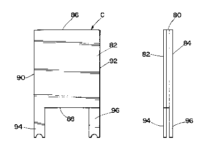
Figures 4-6 show a PTC device C that
includes a central flat layer of PTC material 80
sandwiched between a pair of generally rectangular
flat metal plates 82,84. The periphery of PTC
device C includes top and bottom edges 86,88 and
opposite sides 90,92. Plate 82 has a terminal leg
94 projecting from bottom end 88 in alignment with
side 90. Plate 84 has a terminal leg 96 projecting
from bottom end 88 thereof adjacent side 92. PTC
CLLITOl D: 12g795 1
2 i 75343
-
device C is encapsulated in dielectric material 98
as shown in Figure 6 for increasing the effective
thickness thereof.
Figure 7 shows a PTC device D that
includes a layer of PTC material 100 sandwiched
between opposite flat and rectangular metal plates
102,104. The periphery of PTC device D and of
plates 102,104 includes top and bottom ends 106,108
and opposite sides 110,112. A terminal leg 114
projects outwardly from bottom end 108 of plate 102
adjacent side 110, and another terminal leg 116
projects outwardly from bottom end 108 of plate 104
intermediate opposite sides 110,112. Flanges
118,120 are bent outwardly from plate 102 at top and
bottom ends 106,108 thereof for effectively
increasing the thir~n~sc of PTC device D.
Figure 8 shows a PTC device E having a
middle layer of PTC material 130 sandwiched between
a pair of flat rectangular plates 132,134. PTC
device E and plates 132,134 have an outer periphery
that includes top and bottom ends 136,138 and
opposite sides 140,142. A terminal leg 144 extends
outwardly from bottom end 138 of plate 134 and
another terminal leg 146 extends outwardly from
bottom end 138 of plate 132. Terminal legs 144, 146
are bent substantially perpendicular to plates
132,134. Flanges 146,148 are bent outwardly from
opposite sides 140,142 of plate 132 adjacent bottom
end 138 thereof. Flanges 146,148 increase the
effective thickness of PTC device E and are
substantially perpendicular to their respective
plates.
CLLITOI Dac: 129~795 1
` ` 21 75~43
Figure 9 shows PTC device B having a
central layer of PTC material 150 sandwiched between
a pair of flat rectangular plates 152,154. PTC
device B and plates 152,154 have a periphery that
includes top and bottom ends 156, 158 and opposite
sides 160,162. A terminal leg 164 extends outwardly
from bottom end 158 of plate 152 and a terminal leg
166 extends outwardly from bottom end 158 of plate
154. Terminal legs 164,166 may be bent as indicated
by shadow lines in Figure 9. Top and bottom flanges
170,172 are bent outwardly substantially
perpendicular to plate 152 at top and bottom ends
156,158 thereof. Opposite side flanges 174,176 are
bent outwardly from opposite sides 160, 162 of plate
152. Top and bottom flanges 170,172 are preferably
located intermediate opposite sides 160,162 and have
a width that is substantially less than the length
of top and bottom ends 156, 158. In addition,
flanges 170,172,174 and 176 are bent such that their
outer surfaces are located on or inwardly of the
outer periphery of PTC device B and of plates
152,154.
Figure 10 shows a PTC device F that
includes a central layer of PTC material 180
sandwiched between a pair of rectangular metal
plates 182, 184. PTC device F and plates 182, 184
have top and bottom ends 186,188 and opposite sides
190, 192. Top flanges 194,196 are bent outwardly
from plates 182,184 adjacent top end 186 thereof. A
bottom flange 198 is bent outwardly from plate 182
adjacent bottom end 188 thereof. Terminal legs
200,202 project outwardly from bottom end 188 of
CLLlTOl D: 12g79S I
- 21 75~43
plates 182,184 intermediate opposite sides 190,192.
Plate 184 in Figure 10 has a bottom flange
corresponding to flange 198 that is shown at 204 in
Figure 11.
Figure lla shows PTC device F received in
a pocket 210 having a thick~ec-c substantially
greater than the thickness of PTC device F between
the outer surfaces of plates 182,184. Flanges
194,196 and 198,204 increase the effective thicknP~c
of PTC device F so that it is a close fit within
pocket 210 as shown in Figure lla. Flanges 198,204
also cooperate with abutments adjacent the bottom of
pocket 210 for retaining PTC device F therein while
allowing terminal legs 200,204 to project through
narrow pocket bottom opening 64.
Figures 12 and 13 show PTC device G having
a layer of PTC material 220 sandwiched between
opposite rectangular metal plates 222,224. PTC
device G and plates 222,224 have an outer periphery
that includes top and bottom ends 226,228 and
opposite sides 230,232. A top flange 234 is bent
outwardly from plate 222 adjacent top end 226
thereof intermediate opposite sides 230, 232. A
bottom flange 236 is bent outwardly from bottom end
228 of plate 222 intermediate opposite sides
230,232. Another flange 238 is bent outwardly from
plate 222 adjacent side 230 thereof. Flanges
234,236 and 238 provide an increased effective
thir~n~cc for PTC device G. Plate 222 is notched
adjacent the opposite sides of flanges 234,236 and
238 so that these flanges can be bent with their
outer surfaces located on or inwardly of the
CLLrrOl D~ 12~5 1
21 75~-43
-
--10--
periphery of PTC device G and of plate 222.
Terminal legs 240, 242 project outwardly from plates
222,224 intermediate opposite sides 230,232. A
small bottom flange 244 extends outwardly from plate
224 opposite from flange 238 as shown in Figure 13.
Instead of bending the flanges outwardly
substantially perpendicular to the plates, it will
be recognized that it is possible to simply deform
the plate material outwardly on an inclination in
localized areas. When flanges are used, they allow
increasing the effective thickness of a PTC device
by at least two times. When the plates are deformed
outwardly at an inclination in localized areas, the
increased thickness would generally be less than two
times the combined total thickness of the plates and
PTC material.
Although the invention has been shown and
described with respect to certain preferred
embodiments, it is obvious that equivalent
alterations and modifications will occur to others
scaled in the art upon the reading and unders~n~i~g
of this specification. The present invention
includes all such equivalent alterations and
modifications, and is limited only by the scope of
2S the claims.
CLLITOl Doc: 12g795 1