Language selection

Search

Patent 2175606 Summary

Third-party information liability

Some of the information on this Web page has been provided by external sources. The Government of Canada is not responsible for the accuracy, reliability or currency of the information supplied by external sources. Users wishing to rely upon this information should consult directly with the source of the information. Content provided by external sources is not subject to official languages, privacy and accessibility requirements.

Claims and Abstract availability

Any discrepancies in the text and image of the Claims and Abstract are due to differing posting times. Text of the Claims and Abstract are posted:

  • At the time the application is open to public inspection;
  • At the time of issue of the patent (grant).
(12) Patent: (11) CA 2175606
(54) English Title: PORTABLE CHAINSAWMILL
(54) French Title: SCIERIE A CHAINE PORTATIVE
Status: Expired and beyond the Period of Reversal
Bibliographic Data
Abstracts

English Abstract


A portable chainsawmill that enables on site processing of
timber into dimension lumber ready for construction. The
cutting means is a stationary, vertically upright mounted
chainsaw with a special throttle control. The topside of
the sawbar rips the timber and propels the sawdust in a
downward direction. The sawmount is designed for sideways
positioning of the chainsaw between cuts. The sawmount
permits quick removal of the chainsaw for recharging of
resevoirs or maintenance. The timber conveyance is a
rolling trolley that operates on a flat deck. The trolley
is kept in line with allignment guides. The timber normally
rests on a mill table which is mounted on the trolley. The
timber is secured with a suitable means. The mill table has
slots in it which allow the sawbar nose to pass under the
timber and sawdust to pass. An auxilliary table on the
trolley permits slabs to be cut off of large logs when
necessary and also serves as a catchment or storage area
for lumber being processed. The trolley is pulled through
the sawbar with a winching apparatus. Sawdust is propelled
through an opening in the deck to a pile under the deck.
This complete chainsawmill is modular and very easy to
erect in remote locations.


Claims

Note: Claims are shown in the official language in which they were submitted.

THE EMBODIMENTS OF THE INVENTION IN WHICH AN EXCLUSIVE
PROPERTY OR PRIVILEGE IS CLAIMED ARE DEFINED AS FOLLOWS:
1. A portable chainsawmill which has a log moving and a
chainsaw in a fixed position during sawmilling, a log is
fastened with attachment means to a trolley with a mill
table which rolls lengthwise on a flat wooden deck, said
trolley has rollers complimentary to an allignment system
fastened to said deck comprised of a pair of straight,
parallel, longitudinally extending guide rails which
provide lateral restraint by rubbing fractionally against
the longitudinal outside frame members of said trolley, a
log is cut lengthwise with a through cut in the vertical
plane while it is being moved using a hand winching
apparatus connected by rope to the front of said trolley
which is fastened to said deck thus a log can be completely
moved through the cutting edge of a sawbar, said chainsaw
is fixed in a vertically upright overhead position with
sawbar pointing down and the log is cut using the downward
travelling portion of a chain so that sawdust is propelled
through openings in said trolley mill table and said deck
to the ground, said chainsaw is attached to a sawmount
which provides for sideways repositioning between cuts at a
number of indexed positions coincident with openings in
said trolley mill table, said sawmount is secured to a
pedestal attached to said deck, said sawmount has a part
which separates allowing for removal of a chainsaw for
filling of resevoirs or maintenance, said chainsaw has a
throttle control attached to it's handle.

2. A portable chainsawmill as claimed in claim 1 wherein a
wooden deck has:
(a) a solid flat surface comprised of an area about
eighteen feet long by thirty inches wide bounded on two
parallel sides for a certain distance along it's length by
allignment guides defining a trolley path and an area to
one side of said path large enough to support a sawmount
pedestal;
(b) a pedestal fixed to said deck being a rigid structure
able to secure a sawmount into position, said pedestal to
vertically extend high enough to locate said sawmount at
it's required position above said deck thus defining a
vertical clearance needed for sawmilling;
(c) a rectangular chute opening inside of where said
trolley wheels track and under all positions of a mounted
chainsaw which allows for a substantial part of sawdust
produced to pass to the ground;
11

3. A portable chainsawmill as claimed in claim 1 wherein a
sawmount capable of telescoping sideways to fixed, indexed
positions and capable of securing a chainsaw in a vertical
position at a right angle position to said sawmount being
comprised of;
(a) a square tube fixed portion with a series of holes
drilled vertically through top and bottom flanges that are
at locations which are coincident with positions where a
sliding tube can be anchored by means of a pin inserted
through both;
(b) a square tube sliding portion which slides inside of a
square tube fixed portion having a hole drilled through top
and bottom flanges which line up with any of the indexed
series of holes in said fixed square tube thus giving a
series of locations at which a mounted chainsaw can be
anchored, also said square tube sliding portion has a plate
welded square to one end with a hole in it through which a
bolt can pass to secure a chainsaw in a vertical upright
position;
(c) a pin which passes vertically through one of the holes
in the top flange of said fixed square tube then through a
hole in the top flange of said sliding square tube then
through a hole in the bottom flange of said sliding square
tube then through a hole in the bottom flange of said fixed
square tube thus connecting near rigidly said sliding
square tube to said fixed square tube thus anchoring
securely said chainsaw in position;
(d) a rubber retainer capable of securing said pin in
operating position without vibrating loose.
4. A portable chainsawmill as claimed in claim 1 wherein a
throttle control mechanism is attached to a handle of a
chainsaw, said throttle control mechanism comprises of a
friction fit lever connected to a wire which loops around a
chainsaw throttle trigger and is anchored at it's other
end, said throttle control mechanism moves a chainsaw
throttle trigger and holds it in it's wide open position
during operation.
12

5. A portable chainsawmill as claimed in claim 1 wherein a
trolley capable of rolling horizontally on a flat surface
has a means for attaching a log to it and is is capable of
guiding a log in a direction parallel to said allignment
guides, said trolley is metal frame of a rectangular shape
in plan with a large rubber treaded caster at each of it's
four corners, said frame is rigid with a right hand side
and left hand side longitudinal horizontal member being of
rectangular cross section with a vertical plane surface
which partially engages a vertical plane surface of said
allignment guides in a sliding way thus restraining said
trolley from lateral missallignment, said frame also has
cross members horizontal and at right angles to said
longitudinal members which are supports for a mill table,
an auxilliary table and a timber fastening system, said
frame is of sufficient length to support a ten foot log
with stability and of sufficient width to allow for a mill
table and auxilliary table and have sufficient area in a
horizontal plane which allow for all functions of
sawmilling a ten foot by fourteen inch diameter log, said
frame also is of low profile to allow for low centre of
gravity and efficient operation.
6. A portable chainsawmill as claimed in claim 1 and 5
wherein a mill table is comprised of a series of plywood
sections vertically oriented and running lengthways and on
top of said frame in a pattern which accomodates indexed
positioning of a chainsaw, also said mill table has all
upper edges of said plywood parallel to the long axis of
said frame but above said frame a number of inches, said
plywood has spaces in between so that a sawbar nose can
pass under a log resting on said mill table and over said
frame cross members, said spaces also allow sawdust to pass
downward, said mill table runs lengthways and projects over
each end of said frame a short distance, said mill table is
also wide enough to accomodate at least a fourteen inch
diameter log and long enough to support a ten foot log,
bottom half of said plywood sections are where threaded
rods pass and connect rigidly all plywood sections with an
aid of nuts and washers, said threaded rods anchor said
mill table to said frame to provide an integral unit.
l3

7. A portable chainsawmill as claimed in claim 1 and 5
wherein an auxilliary table is provided to permit slab
cutting on large logs, be a catchment for timber being
processed and be an approach for timber being loaded on to
said trolley.
8. A portable chainsawmill as claimed in claim 1 and 5
wherein a timber fastening system which is integral with
said trolley has upright members with holes in them to
allow for fasteners to pass for securing of timber.
14

Description

Note: Descriptions are shown in the official language in which they were submitted.


2175fi0fi
This invention is an improvement in the sawing of timber
using a chainsaw on a portable sawmill. This invention is
set apart from others in that the chainsaw is mounted in a
fixed vertical position integral with the sawmill deck and
the topside of the bar is used for cutting thus propelling
sawdust downwards; a further improvement is that the log
moves during sawmilling.
An object of the invention is to provide a portable
chainsawmill which is easily transported and easily
assembled or disassembled.
Another object of the invention is to provide a portable
chainsawmill which has few moving parts thus
minimizing maintenance needs and essentially confining
need for maintenance to the chainsaw.
Another object of the invention is to provide a portable
chainsawmill which can dampen the vibration of a high
powered chainsaw.
Another object of the invention is to provide a portable
chainsawmill which provides for clean disposal of sawdust.
Another object of the invention is to provide a portable
chainsawmill which provides for a simple and quick
procedure to refuel the chainsaw.
Another object of the invention is to provide a portable
chainsawmill that provides an action that focuses the
sawyers attention on the log rather than on the chainsaw.
Another object of the invention is to provide a portable
chainsawmill with a secure attachment for the log such that
the force of cutting would aid in keeping the log in place.
Another object of the invention is to provide a portable
chainsawmill in which the action of moving the log provides
for a true line and control of pressure.
Another object of the invention is to provide a portable
chainsawmill which allows for easy log loading.
2

2 17 5 60 6
Another object of the invention is to provide a portable
chainsawmill which produces a wide range of product mix.
Another object of the invention is to provide a portable
chainsawmill which reduces operator fatigue.
Another object of the invention is to provide a portable
chainsawmill that has a way for the chainsaw trigger to
be easily controlled.
3

A brief description of the figures are as follows'
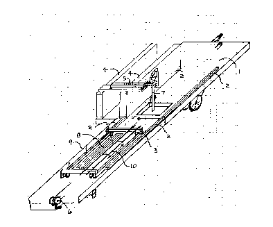
Fig. 1 is a schematic of the preferred embodiment of
the device of the invention:
Fig. 2 is a plan view thereof:
Fig. 3 is a side view thereof:
Fig. 4 is a cross section thereof:
Fig. 5 is a sketch showing in detail the mill table and
means of fastening logs of the device of the
invention:
Fig. 6 is a sketch showing in detail the sawmount of the
device of the invention.
4
v

..2175gp6
A detailed description of the preferred embodiment is
as follows:
The portable chainsawmill of the present invention shown in
Fig.l to Fig 4 of the drawings has the following preferred
embodiment. A deck 1 is constructed of plywood surface
with supporting framework underneath. It is of sufficient
mass to absorb the vibration of a chainsaw. It can be built
as a unit or sectional. It will sit in a level position
about thirty inches off the ground for usage. Inboard and
outboard allignment guides 2 are integral with the deck to
provide true line for the moving trolley 3 on which the log
is fastened. This in turn provides for a true cut during
sawmilling. It will suffice that these allignment guides
guide sideways the trolley. Also, a pedestal 4 to the side
of the path of trolley 3 is integral with the deck and
provides a secure stationary support for the telescoping
sawmount 5. The telescoping sawmount 5 has an action
horizontal and at right angles to the path of the trolley
3. The chainsaw is attached to the moving portion of the
telescoping sawmount 5 with a bolt through the sawbar 7.
The timber is fastened to trolley 3. Connected to the
trolley 3 is a winching system 6 which the operator uses to
pull the trolley 3 with log attached through the chainsaw
which is in a fixed position.
Supplementary description of the telescoping sawmount 5 in
the embodiment shown is as follows. Telescoping sawmount 5
shown on Fig.6 comprises of fixed square tube 13, sliding
square tube 14 and pin 15. Fixed square tube 13 and sliding
square tube 14 secure a chainsaw from rotational movement.
Fixed square tube 13 is rigidly anchored to pedestal 4 thus
making it integral with the deck 1. It has a series of
holes drilled vertically through top and bottom flanges at
indexed positions through which pin 15 can pass. Sliding
square tube 14 has one hole drilled vertically through top
and bottom flanges through which pin 15 can also pass. The
holes in sliding square tube 14 are lined up with one set
of holes in fixed square tube 13 and pin 15 is inserted
from the top passing through both fixed square tube 13 and
sliding square tube 14. A means is used to keep the pin 15
from vibrating out of place. Thus the chainsaw can be fixed
rigidly at any of a number of horizontal positions. At one

m -2~756pfi
end of sliding square tube 14 is a plate welded in the
vertical position and in this plate there is a hole
drilled. Through this hole a bolt will pass which also
passes through a hole in sawbar 7 thus fastening securely a
chainsaw at sawbar 7 with a friction fit connection.
Dismounting of said chainsaw is simply a matter of removing
pin 15 and sliding out said chainsaw with said sliding
square tube 14 attached to it.
Supplementary description of trolley 3 in the embodiment
shown on Fig.l to Fig.5 is as follows. Trolley 3 is a
rectangular shaped frame on four wheels which tracks on the
inside of allignment guides 2 while it rolls on deck 1. The
right hand side and left hand side structural members of
trolley 3 act as guide rails which slide on allignment
guides 2. It will suffice to say that trolley 3 is guided
sideways so as to provide a true line for sawmilling.
Trolley 3 is a welded frame made of a number of
longitudinal members and a number of transverse members
oriented horizontally. At the four corners wheels are
mounted. Also on the left hand side of the frame there are
upright members 11 integral with the frame which provide
anchor posts for timber attachment system 9. Holes are
drilled through these anchor posts at convenient locations
through which attachment screws 12 pass to secure the
timber. Also, trolley 3 has mounted on it mill table 8 as
shown on Fig. S. Said mill table is a series of upright
plywood members which are supported lengthways on the
trolley frame. These plywood members are bolted together
with long threaded rods which are anchored to said trolley
frame. There are gaps between these plywood members which
are accomplished with nuts and washers on said threaded
rods which pass through the bottom half of said plywood
members of said mill table. These gaps are coincident with
fixed positions of the chainsaw provided by said
telescoping sawmount. Also, these gaps allow for the
downward passage of sawdust to the underside of deck 1 with
the only impediment being transverse members of said
trolley frame and said threaded rods with attendant
hardware. Mill table 8 also has a fixed vertical horizon
which is above said trolley frame a number of inches. This
allows the nose of sawbar 7 to pass below the top surface
6

.2~~5sos
of said mill table and over the top of transverse members
of said trolley frame thus allowing the nose of sawbar 7 to
pass under the log which rests on the mill table 8 thus
allowing for a through cut. The downward force of the
cutting action plus the holding force of attachment screws
12 hold the log securely in place. Also, on trolley 3 there
is an auxilliary table 10. Suffice it to say that this
auxilliary table provides a means for preparatory work on
oversized logs and other complimentary functions such as a
catchment for timber, safety space and an approach for logs
being loaded. The mass of said trolley assembly together
with a mounted log allow for a perfectly stable conveyance.
This conveyance in operation works coincidently with pre
determined positions of the chainsaw provide for by the
telescoping sawmount 5 allowing for cuts to be taken in a
variety of patterns.
Supplementary description of winching system 6 in the
embodiment shown is as follows. A modified boat winch is
anchored to the back end and on top of deck 1. A winch rope
passes under trolley 3 and on top of deck 1 to near the
front end of deck 1 and then is returned by pulley to
trolley 3. The operator while turning said winch handle has
complete visibility of the sawmilling operation and is in
the best place to avoid nuiscance sawdust and fumes. Also,
the operator has quick access to a chainsaw trigger.
7

21756p6
In description typical operation of the preferred
embodiment is as follows. A log is rolled laterally onto
mill table 8 which is part of trolley 3. The log is then
secured in place using fasteners 12. Trolley 3 is rolled by
hand to the start position on deck 1 behind the chainsaw.
The chainsaw is then positioned for the desired cut by
locating sliding tube 14 to the indexed location needed. It
is understood that a chainsaw is rigidly fastened to
sliding tube 14 already by means of a bolted friction fit
connection. Once sliding tube 14 is located pin 15 is
inserted down through fixed tube 13 and sliding tube 14.
The pin is kept in place with a suitable retainer 16. The
winching system 6 is then set up to slight tension pull on
a trolley assembly with log attached. A chainsaw is then
started with the trigger engaged to full throttle using a
special throttle control. It will suffice to say that a
special throttle control need only to be able to lock a
chainsaw throttle in the wide open position for sawmilling.
Now with the chainsaw running wide open said trolley
assembly with the log attached is winched by hand through
the sawbar. Sawdust will fly downward through slots in mill
table 8 through an opening in deck 1 to the ground. Once
the cut is completed the loose part will fall onto
auxilliary table 10. A chainsaw will be set to the idle
position using said special throttle control. The cut
portion of the log will be removed and said trolley 3 with
attached log is returned by hand to the start position.
Said chainsaw will be repositioned to another indexed
location using the telescoping sawmount 5. Then the cutting
operation is repeated. For example a sequence of cutting is
outboard slab, inboard slab, loose log, turn log 90degrees,
reattach log, outboard slab then proceed to cut desired
thicknesses of lumber. At any convenient time the chainsaw
can be shut off and removed by removing pin 15 and removing
said chainsaw with sliding tube 14 attached to it. This
will need to be done to refill or maintain a chainsaw.
Also, for oversize logs auxilliary table 10 can be used to
do preparatory work. This system greatly reduces nuiscance
sawdust, focuses the sawyers attention on the log being cut
rather than on a chainsaw and reduces work required
especially as concerns moving a conveyance with a heavy
duty modified boat winch that can be easily turned by hand
thus allowing for perfect control of cutting pressure.
8

._ 2'7560 fi
Mounting and dismounting the chainsaw is also a simple
procedure. The operation of processing logs with this
invention is safe and comfortable.
It will be appreciated that many modifications of the
embodiment disclosed may exist without departing from the
scope of the present invention. Accordingly, it is desired
to protect by Letters Patent which may issue on application
all such embodiments as properly fall within the scope of
our contribution to the art.
9

Representative Drawing
A single figure which represents the drawing illustrating the invention.
Administrative Status

2024-08-01:As part of the Next Generation Patents (NGP) transition, the Canadian Patents Database (CPD) now contains a more detailed Event History, which replicates the Event Log of our new back-office solution.

Please note that "Inactive:" events refers to events no longer in use in our new back-office solution.

For a clearer understanding of the status of the application/patent presented on this page, the site Disclaimer , as well as the definitions for Patent , Event History , Maintenance Fee  and Payment History  should be consulted.

Event History

Description Date
Time Limit for Reversal Expired 2006-05-02
Inactive: Adhoc Request Documented 2006-02-06
Letter Sent 2005-05-02
Inactive: Office letter 2004-07-27
Change of Address Requirements Determined Compliant 2004-06-23
Inactive: Office letter 2004-06-23
Letter Sent 2004-05-03
Inactive: Single transfer 2004-04-23
Change of Address or Method of Correspondence Request Received 2004-04-23
Inactive: Adhoc Request Documented 2004-03-29
Grant by Issuance 2000-10-03
Inactive: Cover page published 2000-10-02
Pre-grant 2000-07-04
Inactive: Final fee received 2000-07-04
Notice of Allowance is Issued 2000-02-28
Letter Sent 2000-02-28
Notice of Allowance is Issued 2000-02-28
Inactive: Status info is complete as of Log entry date 2000-02-24
Inactive: Application prosecuted on TS as of Log entry date 2000-02-24
Inactive: Approved for allowance (AFA) 1999-10-08
Application Published (Open to Public Inspection) 1997-11-03
Request for Examination Requirements Determined Compliant 1996-09-06
All Requirements for Examination Determined Compliant 1996-09-06

Abandonment History

There is no abandonment history.

Maintenance Fee

The last payment was received on 2000-03-31

Note : If the full payment has not been received on or before the date indicated, a further fee may be required which may be one of the following

  • the reinstatement fee;
  • the late payment fee; or
  • additional fee to reverse deemed expiry.

Please refer to the CIPO Patent Fees web page to see all current fee amounts.

Fee History

Fee Type Anniversary Year Due Date Paid Date
MF (application, 2nd anniv.) - small 02 1998-05-04 1998-04-09
MF (application, 3rd anniv.) - small 03 1999-05-03 1999-04-23
MF (application, 4th anniv.) - small 04 2000-05-02 2000-03-31
Final fee - small 2000-07-04
MF (patent, 5th anniv.) - small 2001-05-02 2001-04-05
MF (patent, 6th anniv.) - small 2002-05-02 2002-04-22
MF (patent, 7th anniv.) - small 2003-05-02 2003-04-03
MF (patent, 8th anniv.) - small 2004-05-03 2004-04-23
Owners on Record

Note: Records showing the ownership history in alphabetical order.

Current Owners on Record
ROBERT BURKHART
Past Owners on Record
None
Past Owners that do not appear in the "Owners on Record" listing will appear in other documentation within the application.
Documents

To view selected files, please enter reCAPTCHA code :


To view images, click a link in the Document Description column. To download the documents, select one or more checkboxes in the first column and then click the "Download Selected in PDF format (Zip Archive)" or the "Download Selected as Single PDF" button.

List of published and non-published patent-specific documents on the CPD .

If you have any difficulty accessing content, you can call the Client Service Centre at 1-866-997-1936 or send them an e-mail at CIPO Client Service Centre.


Document
Description 
Date
(yyyy-mm-dd) 
Number of pages   Size of Image (KB) 
Cover Page 1997-12-04 1 59
Abstract 1999-10-06 1 41
Description 1999-10-06 6 301
Claims 1999-10-06 5 188
Drawings 1999-10-06 6 386
Cover Page 1998-08-21 1 59
Abstract 1999-11-09 1 36
Description 1999-11-09 8 303
Claims 1999-11-09 5 188
Cover Page 1996-08-09 1 14
Description 1996-08-09 4 233
Drawings 1996-08-09 6 284
Claims 1996-08-12 2 93
Abstract 1996-08-12 1 48
Cover Page 2000-09-13 1 71
Representative drawing 2000-09-13 1 37
Notice: Maintenance Fee Reminder 1998-02-03 1 120
Notice: Maintenance Fee Reminder 1999-02-03 1 118
Notice: Maintenance Fee Reminder 2000-02-03 1 121
Commissioner's Notice - Application Found Allowable 2000-02-28 1 166
Notice: Maintenance Fee Reminder 2001-02-05 1 120
Notice: Maintenance Fee Reminder 2002-02-05 1 119
Notice: Maintenance Fee Reminder 2003-02-04 1 115
Notice: Maintenance Fee Reminder 2004-02-03 1 116
Maintenance Fee Notice 2004-06-28 1 172
Notice: Maintenance Fee Reminder 2005-02-03 1 117
Maintenance Fee Notice 2005-06-27 1 172
Second Notice: Maintenance Fee Reminder 2005-11-03 1 117
Notice: Maintenance Fee Reminder 2006-02-06 1 119
Fees 2003-04-03 2 76
Correspondence 2000-07-04 1 108
Fees 1998-04-09 1 74
Fees 2000-03-31 2 60
Fees 2002-04-22 3 164
Fees 2001-04-05 2 143
Fees 1999-04-23 1 22
Correspondence 2004-02-03 3 139
Correspondence 2004-04-23 1 34
Correspondence 2004-06-23 1 11
Correspondence 2004-07-27 1 11
Fees 2004-04-23 3 134
Prosecution correspondence 1996-05-02 37 1,960
Prosecution correspondence 1999-06-04 3 340
Prosecution correspondence 1999-11-09 2 320
Prosecution correspondence 1999-04-23 1 41
Prosecution correspondence 1996-09-06 1 44
Maintenance fee correspondence 1996-09-06 1 60
Courtesy - Office Letter 1996-10-07 1 38
Examiner Requisition 1999-03-18 2 67