Language selection

Search

Patent 2175845 Summary

Third-party information liability

Some of the information on this Web page has been provided by external sources. The Government of Canada is not responsible for the accuracy, reliability or currency of the information supplied by external sources. Users wishing to rely upon this information should consult directly with the source of the information. Content provided by external sources is not subject to official languages, privacy and accessibility requirements.

Claims and Abstract availability

Any discrepancies in the text and image of the Claims and Abstract are due to differing posting times. Text of the Claims and Abstract are posted:

  • At the time the application is open to public inspection;
  • At the time of issue of the patent (grant).
(12) Patent: (11) CA 2175845
(54) English Title: WASH-UP DEVICE WASHING PRINTING UNITS OF A ROTARY PRINTING MACHINE
(54) French Title: DISPOSITIF DE NETTOYAGE DES ELEMENTS IMPRIMANTS D'UNE MACHINE D'IMPRESSION ROTATIVE
Status: Expired and beyond the Period of Reversal
Bibliographic Data
(51) International Patent Classification (IPC):
  • B41F 35/00 (2006.01)
  • B41F 35/02 (2006.01)
  • B41F 35/06 (2006.01)
(72) Inventors :
  • LOFTUS, GEOFFREY (United States of America)
  • DETMERS, ANDREAS (Germany)
(73) Owners :
  • HEIDELBERGER DRUCKMASCHINEN AG
(71) Applicants :
  • HEIDELBERGER DRUCKMASCHINEN AG (Germany)
(74) Agent: DENNISON ASSOCIATES
(74) Associate agent:
(45) Issued: 2000-03-14
(22) Filed Date: 1996-05-06
(41) Open to Public Inspection: 1996-11-05
Examination requested: 1995-05-06
Availability of licence: N/A
Dedicated to the Public: N/A
(25) Language of filing: English

Patent Cooperation Treaty (PCT): No

(30) Application Priority Data:
Application No. Country/Territory Date
P 195 16 068.1 (Germany) 1995-05-04

Abstracts

English Abstract


The invention relates to a device washing printing units and adjacent areas in a rotary
printing machine, with the printing units comprising a printing-forme cylinder and a
blanket cylinder and cooperating with an impression cylinder. A wash-up device
washing the outer cylindrical surface of printing-forme cylinder or blanket cylinder is
assigned to each printing unit. To a printing unit (3, 4, 5, 6) is assigned a sucking unit
(8) in the wedge-shaped area (20), the outlets (19) of said sucking units (8) being
essentially directed towards the outer cylindrical surfaces (15, 16) of the printing-unit
cylinders (13, 14).


Claims

Note: Claims are shown in the official language in which they were submitted.

THE EMBODIMENTS OF THE INVENTION IN WHICH AN EXCLUSIVE
PROPERTY OR PRIVILEGE IS CLAIMED ARE DEFINED AS FOLLOWS:
1. Printing units for a direct imaging rotary printing press, each of the
printing units comprising:
a printing unit body having sidewalls;
a printing-form cylinder having an outer cylindrical surface
disposed on said side walls;
a directly imageable printing form having a surface disposed on
said outer cylindrical surface of said printing-form cylinder;
a blanket cylinder having an outer cylindrical surface
cooperating with an impression cylinder, said blanket cylinder
disposed on said side walls;
a cleaning assembly having a wash-up device for washing said
outer cylindrical surface of said printing-form cylinder and said
blanket cylinder after a direct imaging of said printing form; and
said cleaning assembly having a sucking unit disposed in a
wedge-shaped nip region between said printing-form cylinder
and said blanket cylinder, said sucking unit having at least one
opening directed substantially towards said outer cylindrical
surface of said printing form cylinder and said outer cylindrical
surface of said blanket cylinder for the removal of silicon
particles.
2. The printing unit according to claim 1, wherein said sucking unit is
one of a plurality of sucking units and said wash-up device cooperates with at
least one of said sucking units.
3. The printing unit according to claim 1, wherein said sucking unit
includes rotating brushes.
-4-

4. The printing unit according to claim 1, wherein said sucking unit
includes rubber-covered roller bodies.
5. The printing unit according to claim 1, wherein said sucking unit is
connected to a controllable vacuum source.
-5-

Description

Note: Descriptions are shown in the official language in which they were submitted.


217 ~ ~~~5
A1531 05.03.1996mo
Wash-up device washing printing units of a rotary printing machine
The in~~ention relates to a wash-up device washing printing units of a rotary
printing
machine.
Rotay printing machines, in general, as well as rotary printing machines in
which the
printing forrne is directly imaged in the printing machine involve the problem
that paper
dust and dried ink residues have to be removed from the inking unit or
printing unit in
order not to ai~ect the print quality. Manual washing is complicated and time-
consuming; with respect to the locations in the printing unit which are hard
to reach the
washing results are not satisfactory.
As compared to washing printing units of conventional printing machines,
printing
machines with direct imageable printing formes require that, in particular,
silicone
residues and other aforementioned particles are removed from printing unit and
inking
unit.
Mechanical devices such as brushes or electrostatic elements have proven
inadequate to
remove the aforementioned residues.
It is thus the object of the invention to ensure washing of the printing units
and adjacent
areas so that, without any manual interference, residues may be removed to a
large
extent .
According to the invention this object is achieved by the features of Claim 1.
The sucking unit is connected to a controllable vacuum source, thus
influencing the
suction force and controlling the suction output of the sucking unit. Since
the outlets of
the sucking unit face the outer cylindrical surfaces of both printing-unit
cylinders,
residues may be removed from the outer cylindrical surfaces of both cylinders
and from
the adjacent wedge-shaped area.

21'~ 5 ~~5
- 2 - A1531 05.03.1996mo
Further details are mentioned in the sub-claims.
The invention is explained in greater detail with reference to a drawing.
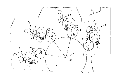
Fig. l is a side elevational view of a printing machine operating according to
the
satellite principle, and
Fig. 2 shows a detail of the wedge-shaped area between two printing-unit
cylinders.
Fig. 1 is a side elevational view of a rotary printing machine designed, for
example,
according to the satellite principle.
An impression cylinder 1 the circumference of which may receive a plurality of
print
sheets at once is mounted in side walls 2. Printing units 3, 4, 5, and 6
disposed in a
satellite-type manner and printing the sheets held on the outer cylindrical
surface of
impression cylinder 1 are assigned to said impression cylinder 1.
Each of said printing units 3, 4 , 5 and 6 comprises a printing-forme cylinder
13 and a
blanket cylinder 14 cooperating with each other. The ink transport to the
printing forme
cylinder 13 is erected through an inking unit, with forme rollers 11, 19
applying the ink
onto the printing forme. A wash-up device 7 is assigned to the outer
cylindrical surface
of the printing-forme cylinder 13. Furthermore, a sucking unit 8 which has
been moved
as close as possible to the outer cylindrical surfaces of the cooperating
printing-unit
cylinders 13 and 14 is assigned to each printing unit in the wedge-shaped area
20. In the
fourth printing unit 6 the wash-up device 7 is directly followed by the
sucking unit so
that loosened ink residues or other particles such as silicone particles may
be removed
from the printing unit immediately after having been loosened. Moreover, in
the fourth
printing unit 6 a second sucking unit 8 is provided in the cylinder wedge-
shaped area
above the cooperating printing-unit cylinders.

217845
- 3 - A1531 05.03.1996mo
Fig. 2 shows details of the wedge-shaped area between two printing-unit
cylinders.
Fig. 2 is an enlarged view of the printing-forme cylinder 13 and the blanket
cylinder 14
of a printing unit. A wash-up device 7 is provided below the printing-forme
cylinder 13.
Furthermore, forme rollers 10, 11 provided for the ink transport are engaged
at the
outer cylindrical surface 15 of the printing-forme cylinder 13. A sucking unit
8 is
disposed in the wedge-shaped area 20 of the two cooperating printing-unit
cylinders 13,
14. Said sucking unit 8 is designed as a suction connection 17 featuring
outlets 19
formed in a tubular hollow body. Each of said outlets 19 formed in said
tubular hollow
body is essentially directed towards the outer cylindrical surfaces 15, 16 of
the two
cooperating printing-unit cylinders 13, 14. If the suction connection is
connected to a
controllable vacuum source not illustrated, the hollow body 18 and the outlets
19 are
supplied with a vacuum which removes all particles - silicone, paper, dust -
and other,
for example, dried residues from the wedge-shaped area 20, after having been
loosened
by the wash-up device 7, from the wedge-shaped area 20. In a manner not set
forth in
this embodiment the sucking unit 8 may also be provided directly next to the
wash-up
device 7 so that, immediately after the outer cylindrical surfaces 13, 14 have
passed
the wash-up device 7, loosened ink residues and silicone particles may be
directly
removed from the outer cylindrical surface 15 of the printing-forme cylinder
13 .
In a further embodiment of the inventive solution it is conceivable to
connect, for
example, all sucking units disposed on the printing-units 3, 4, 5, and 6 in a
satellite-type
manner to a single vacuum source and to provide devices ensuring individual
measurements of the vacuum which is controllable for each printing unit by
means of
the respective sucking unit assigned.

Representative Drawing
A single figure which represents the drawing illustrating the invention.
Administrative Status

2024-08-01:As part of the Next Generation Patents (NGP) transition, the Canadian Patents Database (CPD) now contains a more detailed Event History, which replicates the Event Log of our new back-office solution.

Please note that "Inactive:" events refers to events no longer in use in our new back-office solution.

For a clearer understanding of the status of the application/patent presented on this page, the site Disclaimer , as well as the definitions for Patent , Event History , Maintenance Fee  and Payment History  should be consulted.

Event History

Description Date
Inactive: IPC from MCD 2006-03-12
Time Limit for Reversal Expired 2005-05-06
Letter Sent 2004-05-06
Grant by Issuance 2000-03-14
Inactive: Cover page published 2000-03-13
Pre-grant 1999-12-07
Inactive: Final fee received 1999-12-07
Letter Sent 1999-08-12
Notice of Allowance is Issued 1999-08-12
Inactive: Status info is complete as of Log entry date 1999-08-09
Inactive: Application prosecuted on TS as of Log entry date 1999-08-09
Inactive: Approved for allowance (AFA) 1999-07-27
Application Published (Open to Public Inspection) 1996-11-05
All Requirements for Examination Determined Compliant 1995-05-06
Request for Examination Requirements Determined Compliant 1995-05-06

Abandonment History

There is no abandonment history.

Maintenance Fee

The last payment was received on 1999-04-26

Note : If the full payment has not been received on or before the date indicated, a further fee may be required which may be one of the following

  • the reinstatement fee;
  • the late payment fee; or
  • additional fee to reverse deemed expiry.

Please refer to the CIPO Patent Fees web page to see all current fee amounts.

Fee History

Fee Type Anniversary Year Due Date Paid Date
MF (application, 2nd anniv.) - standard 02 1998-05-06 1998-05-01
MF (application, 3rd anniv.) - standard 03 1999-05-06 1999-04-26
Final fee - standard 1999-12-07
MF (patent, 4th anniv.) - standard 2000-05-08 2000-05-03
MF (patent, 5th anniv.) - standard 2001-05-07 2001-04-25
MF (patent, 6th anniv.) - standard 2002-05-06 2002-04-30
MF (patent, 7th anniv.) - standard 2003-05-06 2003-04-24
Owners on Record

Note: Records showing the ownership history in alphabetical order.

Current Owners on Record
HEIDELBERGER DRUCKMASCHINEN AG
Past Owners on Record
ANDREAS DETMERS
GEOFFREY LOFTUS
Past Owners that do not appear in the "Owners on Record" listing will appear in other documentation within the application.
Documents

To view selected files, please enter reCAPTCHA code :


To view images, click a link in the Document Description column. To download the documents, select one or more checkboxes in the first column and then click the "Download Selected in PDF format (Zip Archive)" or the "Download Selected as Single PDF" button.

List of published and non-published patent-specific documents on the CPD .

If you have any difficulty accessing content, you can call the Client Service Centre at 1-866-997-1936 or send them an e-mail at CIPO Client Service Centre.


Document
Description 
Date
(yyyy-mm-dd) 
Number of pages   Size of Image (KB) 
Cover Page 2000-02-01 1 37
Description 1996-08-16 4 136
Cover Page 1996-08-16 1 18
Abstract 1996-08-16 1 16
Claims 1996-08-16 1 28
Drawings 1996-08-16 2 30
Claims 1999-07-27 2 48
Description 1999-07-27 3 124
Representative drawing 2000-02-01 1 10
Representative drawing 1998-04-01 1 18
Reminder of maintenance fee due 1998-01-07 1 111
Commissioner's Notice - Application Found Allowable 1999-08-12 1 163
Maintenance Fee Notice 2004-07-02 1 172
Correspondence 1999-12-07 1 33
Correspondence 1996-07-16 1 22