Language selection

Search

Patent 2175954 Summary

Third-party information liability

Some of the information on this Web page has been provided by external sources. The Government of Canada is not responsible for the accuracy, reliability or currency of the information supplied by external sources. Users wishing to rely upon this information should consult directly with the source of the information. Content provided by external sources is not subject to official languages, privacy and accessibility requirements.

Claims and Abstract availability

Any discrepancies in the text and image of the Claims and Abstract are due to differing posting times. Text of the Claims and Abstract are posted:

  • At the time the application is open to public inspection;
  • At the time of issue of the patent (grant).
(12) Patent: (11) CA 2175954
(54) English Title: A TAP OR VALVE
(54) French Title: ROBINET
Status: Expired and beyond the Period of Reversal
Bibliographic Data
(51) International Patent Classification (IPC):
  • B65D 47/30 (2006.01)
  • A61F 5/442 (2006.01)
  • A61M 39/22 (2006.01)
(72) Inventors :
  • FALCONER, MALCOLM IAN (United Kingdom)
(73) Owners :
  • E. R. SQUIBB & SONS, INC.
  • CONVATEC TECHNOLOGIES INC.
(71) Applicants :
  • E. R. SQUIBB & SONS, INC. (United States of America)
(74) Agent: OSLER, HOSKIN & HARCOURT LLP
(74) Associate agent:
(45) Issued: 2008-01-29
(22) Filed Date: 1996-05-07
(41) Open to Public Inspection: 1997-11-08
Examination requested: 2003-01-27
Availability of licence: N/A
Dedicated to the Public: N/A
(25) Language of filing: English

Patent Cooperation Treaty (PCT): No

(30) Application Priority Data: None

Abstracts

English Abstract


An aim of the invention is to provide a simple and effective one-piece tap
which can be readily and economically manufactured. A tap for a liquid
container
is made from natural or synthetic rubber or a resilient plastics material. It
has a
base portion 10 having an orifice 12 which serves as a liquid inlet therein,
the base
portion embodying a liquid exit means 14. It also has a resilient deformable
closure
portion 20, the closure portion being constructed to make a resilient snap-on
connection with the periphery of the base portion, the closure portion being
manipulatable and having a centrally located plug 22 extending towards the
base
portion. This plug can obturate orifice 12 thereby closing the liquid inlet.
The
closure portion 20 also has a projecting portion 23 extending generally
perpendicularly away from the base portion, the projecting portion being
constructed
so that it can be pushed towards the base portion in order to remove the plug
from
the orifice and so permit liquid to pass to the liquid exit means 14.


Claims

Note: Claims are shown in the official language in which they were submitted.

CLAIMS
1. A tap for a liquid container, made from natural or synthetic rubber or a
resilient
plastics material, which comprises a base portion (10) having an orifice (12)
which serves as
a liquid inlet therein, a closure portion (20), and a tap exit (14), the
closure portion (20) being
constructed to make a snap-on connection with a periphery (17) of the base
portion (10), the
closure portion (20) comprising a resiliently deformable zone (24, 25) and a
non-deformable
zone (23), the non-deformable zone having a pushable projecting portion
extending away
from the base portion and a plug (22) extending towards the base portion, the
deformable
zone (24, 25) biasing the plug (22) so as to obturate the orifice (12) and
close the liquid inlet,
characterised in that the deformable zone (24, 25) is configured as a hinge
such that, when the
non-deformable zone (23) is pushed, the deformable zone (24, 25) hinges so as
to tilt the plug
(22) away from the inlet orifice (12) by a hinge action, thereby permitting
the flow of liquid
to the tap exit.
2. A tap according to claim 1, wherein the base portion (10) comprises a first
surface and
a second surface, the closure portion (20) being mounted on the first surface,
the deformable
zone (24, 25) biasing the plug (22) in a direction from the closure portion
(20) towards the
first surface, and wherein, when the non-deformable zone (23) is pushed, the
plug (22) lifts
away from the first surface.
3. A tap according to claim 1 or 2, wherein the non-deformable zone (23) of
the closure
portion (20) is thicker than the deformable zone (24, 25).
4. A tap according to any one of claims 1, 2 or 3, wherein the non-deformable
zone (23)
has a sloping portion on which the plug (22) is carried.
5. A tap according to claim 4, wherein the sloping portion is located
centrally of the
closure portion (20).
6. A tap according to any one of claims 1, 2, 3 or 4, wherein the tap exit
(14) is
embodied in the base portion (10).
7. A combination of a tap according to any one of claims 1 to 6, and a
urostomy pouch
(30), the base portion (10) being attached to the exterior of the pouch with
the orifice (12) in
registry with a hole in the pouch wall.

8. A combination of a tap as defined in any one of claims 1 to 6, and a night
drainage
adapter (40).
9. A combination according to claim 8, wherein the night drainage adapter (40)
comprises a tube having an end portion insertable into the exit of the tap, so
as to prevent
obturation of the orifice (12) by the plug (22) of the closure portion (20).
10. A combination according to claim 9, wherein the end portion is tapered.
11. A combination according to claim 9, wherein the end portion of the tube is
shaped so
as to force, upon insertion of the tube into the exit of the tap, said closure
portion (20) away
from the base portion (10) and said plug (22) from the inlet orifice (12).
6

Description

Note: Descriptions are shown in the official language in which they were submitted.


2175954
A TAP OR VALVE
This invention relates to a tap or valve and particularly although not
exclusively to a tap for a urostomy pouch.
Various designs of taps or dispensing spigots have been proposed. See for
examaple Fattori et al U.S. Patents Nos. 3,400,866 and 4,787,538, Welsh U.S.
Patent No. 3,972,452, European Patent Application No. 95861A and Scholle U.S.
Patent No. 4,211,348. These designs, in the Applicants' opinion, fall short in
that
tliey are lacking in simplicity. Most are completely unsuitable for employment
in
a urostomv pouch.
It is an aim of the invention to provide a simple and effective easily-
assembled tap which can be readily and economically manufactured.
AccordinQ to tlie invention there is provided a tap for a liquid container,
-nade trom natural or synthetic rubber or a resilient plastics material, which
is comprises a base portion having an orifice wilich serves as a liquid inlet
therein, the
base portion embodying a liquid exit meails. and a resilient deformable
closure
portion. the closure portion being constructed to -nake a resilient snap-on
connection
witli the periphery of the base portion, the closure portion being
manipulatable and
having a centrally located plug extending towards the base portion which can
obturate said orifice thereby closing the liquid inlet, the closure portion
also having
a projecting portion extending generally perpendicularly away from the base
portion,
the projecting portion being constructed so that it can be pushed towards the
base
portion in order to remove the plug from the orifice and so permit liquid to
pass to
the liquid exit means.
In a preferred embodiment of the invention, the closure portion is a wall
which is generally oval in shape as seen in front elevation and has an
external
thickened sloping portion upon wliich the said plug is internally mounted. The
sloping portion is located generally centrally of the closure portion. In the
embodiment of the invention which consists of a urostomy pouch, the base
portion
including the liquid exit means thereof is constructed for attachment, e.g. by
heat
1

CA 02175954 2005-08-23
or R.F. welding, to one wall of the pouch, the pouch having an aperture in one
of
its walls, the aperture being in registry with the liquid inlet orifice.
In an advantageous embodiment of the invention, a night drainage adapter
may be used with, and temporarily incorporated in, the tap described and
illustrated
herein. This adapter device comprises a tube extension of a particular shape
which
when inserted into the liquid exit means, holds the closure portion away from
the
liquid entry hole in the base portion. This permits intermittent night
drainage to
occur, with no manipulation to open the tap being necessary.
The invention will be better understood from the following description of an
io illustrative embodiment, in which like parts are represented by like
reference
numerals, and in which:-
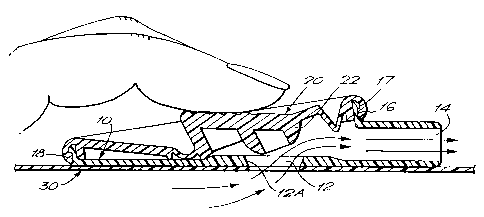
Figure 1 is a front view of one example of tap according to the invention;
Figure 2 is a cross-section on the plane II-II in Figure 1 showing the tap in
its open condition and diagrammatically illustrating part of a wall of a
urostomy
pouch;
Figure 3 is a view identical to Figure 2 but showing the tap in its normally
closed condition;
Figure 4 is a cross-sectional view of a tap having a night drainage adapter
in place; and
Figure 5 illustrates an optional refinement in the form of a peripheral groove
on the drain tube, which allows attachment of a known type of tube connector
(see
UK Patent 2,092,690;\EP 57057B ).
Referring to Figures 1-3, the illustrated tap comprises a base portion 10 and
a closure portion 20. The wall of a urostomy pouch which is the currently
preferred
example of product in which the tap may be employed, is shown at 30 in Figures
2 and 3.
The base portion 10 comprises a central orifice 12 and embodies a liquid exit
means 14. The base portion has a peripheral wall 16, and carried by this wall
is an
outwardly extending rim 17 provided to enable snap-on engagement between
itself
and a connection means 21 on the periphery of the closure portion 20. The base
2

2175954
portion 10 lias a flat surface l0A which may be plastics welded or adhesively
secured or fastened in any other convenient way to the wall 30 of the liquid
container.
The peripheral snap-on connection means 21 of the closure portion is
designed to co-operate with the peripheral wall 16 of the base portion. The
closure
portion is made of a resilient deformable material, preferably a
thermoplastics
elastomer. The closure portion has a centrally located plug 22, which extends
towards the base portion 10 and is shaped to make a complementary mating
engagement with the wall 12A of the orifice 12. The closure portion has a
peripheral slot 18, in which is received the wall 16.
The left-hand end as seen in Figure 2 or Figure 3 of the base and closure
portions will be uppermost in use of the tap, with the liquid exit means 14
being
lowermost.
The closure portion 20 is a plastics moulding, and has a thickened portion
which in the closed position of the tap is at an angle to the'vertical and in
the
tap's open position occupies an approxiinately vertical position. This may be
achieved by manipulating the closure portion 20 witli a finger as illustrated
in Figure
2. This manipulation is faciliated by the fact that the thickness of the
closure
portion is substantially reduced at the zones 24 and 25 and is reduced but to
a lesser
extent at the zone 26. The zones 24 and 25 readily deform to enable the
closure
portion to take up its open position as illustrated in Figure 2.
One desirable advantage of this design of tap is that its overall thickness is
small. Hence, a pouch having this design of tap is unobtrusive when worn.
Another advantage is that the closure portion 20 immediately reverts to the
closed
position as seen in Figure 3 when the finger pressure is removed from the
portion
23 thereof. The complementary shaping of the plug 22 and the wall 12A, and the
interfit between the parts 16, 17, 18, assist in achieving a durable and
leakproof fit.
The tap as illustrated in Figures 1-3 has no detachable parts which might
become
misplaced or lost.
A night drainage adapter 40 is illustrated in Figure 4 in position within the
3

2175954
tap. The adapter 40 comprises a tapered tube having a ribbed end 42, a flange
44,
a taper 46 at its upper end in use, and a hole 48 of a size slightly greater
than the
holle 12 in the base portion 10. The ribbed end 42 facilitates connection to a
drain
tube 50. As will be seen in Figure 4, the adapter 40 when inserted upwardly
into
the tap, forces the closure portion away from the base portion 10. The
resilience
of the closure portion holds the adaptor 40 into close engagement with the
surface
of the base portion. Liquid entering via hole 12 is then guided by adapter 40
directly to the train tube 50.
Referring now to Figure 5, at the lower end of the drain tube 50 a peripheral
io groove 52 is provided, to receive hook members 54 of a known connector,
provided
to convey liquid, e.g. to a night drainage bag or reservoir.
4

Representative Drawing
A single figure which represents the drawing illustrating the invention.
Administrative Status

2024-08-01:As part of the Next Generation Patents (NGP) transition, the Canadian Patents Database (CPD) now contains a more detailed Event History, which replicates the Event Log of our new back-office solution.

Please note that "Inactive:" events refers to events no longer in use in our new back-office solution.

For a clearer understanding of the status of the application/patent presented on this page, the site Disclaimer , as well as the definitions for Patent , Event History , Maintenance Fee  and Payment History  should be consulted.

Event History

Description Date
Time Limit for Reversal Expired 2011-05-09
Letter Sent 2010-05-28
Letter Sent 2010-05-07
Letter Sent 2010-04-01
Grant by Issuance 2008-01-29
Inactive: Cover page published 2008-01-28
Letter Sent 2007-10-23
Inactive: Single transfer 2007-10-04
Pre-grant 2007-10-04
Inactive: Final fee received 2007-10-04
Inactive: Office letter 2007-08-14
Inactive: Correspondence - Prosecution 2007-06-18
Letter Sent 2007-05-29
Notice of Allowance is Issued 2007-05-29
Inactive: Approved for allowance (AFA) 2007-03-26
Amendment Received - Voluntary Amendment 2006-02-06
Inactive: S.30(2) Rules - Examiner requisition 2005-12-22
Amendment Received - Voluntary Amendment 2005-08-23
Inactive: S.30(2) Rules - Examiner requisition 2005-05-10
Inactive: Status info is complete as of Log entry date 2003-02-05
Letter Sent 2003-02-05
Inactive: Application prosecuted on TS as of Log entry date 2003-02-05
All Requirements for Examination Determined Compliant 2003-01-27
Request for Examination Requirements Determined Compliant 2003-01-27
Application Published (Open to Public Inspection) 1997-11-08

Abandonment History

There is no abandonment history.

Maintenance Fee

The last payment was received on 2007-04-17

Note : If the full payment has not been received on or before the date indicated, a further fee may be required which may be one of the following

  • the reinstatement fee;
  • the late payment fee; or
  • additional fee to reverse deemed expiry.

Please refer to the CIPO Patent Fees web page to see all current fee amounts.

Owners on Record

Note: Records showing the ownership history in alphabetical order.

Current Owners on Record
E. R. SQUIBB & SONS, INC.
CONVATEC TECHNOLOGIES INC.
Past Owners on Record
MALCOLM IAN FALCONER
Past Owners that do not appear in the "Owners on Record" listing will appear in other documentation within the application.
Documents

To view selected files, please enter reCAPTCHA code :


To view images, click a link in the Document Description column. To download the documents, select one or more checkboxes in the first column and then click the "Download Selected in PDF format (Zip Archive)" or the "Download Selected as Single PDF" button.

List of published and non-published patent-specific documents on the CPD .

If you have any difficulty accessing content, you can call the Client Service Centre at 1-866-997-1936 or send them an e-mail at CIPO Client Service Centre.


Document
Description 
Date
(yyyy-mm-dd) 
Number of pages   Size of Image (KB) 
Representative drawing 1997-11-26 1 9
Cover Page 1998-08-24 2 64
Cover Page 1996-05-07 1 14
Abstract 1996-05-07 1 25
Description 1996-05-07 4 156
Claims 1996-05-07 2 48
Drawings 1996-05-07 3 60
Cover Page 1997-11-26 2 64
Claims 2005-08-23 2 68
Description 2005-08-23 4 156
Claims 2006-02-06 2 64
Representative drawing 2007-06-05 1 11
Cover Page 2008-01-03 1 45
Reminder of maintenance fee due 1998-01-20 1 111
Reminder - Request for Examination 2003-01-08 1 113
Acknowledgement of Request for Examination 2003-02-05 1 173
Commissioner's Notice - Application Found Allowable 2007-05-29 1 164
Courtesy - Certificate of registration (related document(s)) 2007-10-23 1 104
Maintenance Fee Notice 2010-06-21 1 170
Correspondence 2007-08-14 1 52
Correspondence 2007-10-04 2 67
Correspondence 2010-02-26 5 162