Note: Descriptions are shown in the official language in which they were submitted.
2176087
STARTER WITH PINION RETREAT PREVENTING S~LKU~1UKE
BACKGROUND OF THE INVENTION
1. Field of the Invention:
The present invention relates to a starter for
start-up or cranking of an engine.
2. Related Art:
According to a conventional pinion detent structure in
a starter for an engine, a pinion is pushed against a ring
gear side by operating a lever under the action of a plunger
attracting force in an electromagnet switch, to thereby
prevent disengagement of the pinion from the ring gear. In
this case it is necessary that a relation between the stroke
from a rest position of the pinion up to a meshing position
with the ring gear and the stroke of the plunger be determined
by adjusting the ratio (lever ratio) in moving distance
between a force-applied point and a working point of the
lever. This means that if the levér ratlo is set large, the
plunger stroke can be made small, but instead it becomes
necessary to create a large plunger attracting force, and that
if the lever ratio is set small, the plunger attracting force
can be set small, but instead it becomes necessary to provide
a large plunger stroke. This point has been an obstacle to
the reduction in size of the electromagnet switch.
On the other hand, in Japanese Utility Model Laid-Open
No. 57-36763 and Japanese Patent Laid-Open No. 50-18915, there
is disclosed a structure wherein by restricting the rotation
2 17 6 0 87
of a clutch including a pinion, the pinion is allowed to
advance toward a ring gear under the action of a helical
spline of an output shaft and the action of a rotating force
of a starter motor, and after meshing of the pinion with the
ring gear, a shaft is pushed out in the radial direction
toward the rear end of a clutch adapted to rotate integrally
with the pinion, to restrict the retreat of the clutch,
thereby preventing disengagement of the pinion from the ring
gear. Acçording to this structure, since the moving direction
of the pinion and the clutch and the operating direction of
the retreat restricting shaft are orthogonal to each other, an
electromagnet switch which drives the shaft need not have an
attractive force enough to overcome the returning force of the
pinion, thus making it possible to reduce the size of the
electromagnet switch.
However, in the above-described structure which
utilizes the attractive force of the electromagnet switch to
drive the shaft, the clutch is supported at only one point in
the circumferential direction at the time of restricting the
retreat of the clutch in a meshed state of pinion and ring
gear, and therefore the pinion-ring gear meshing is performed
in an inclined state of the pinion relative to the output
shaft. Consequently, there occurs problems such as local wear
and the generation of noise. Further, since the rotating
force of the pinion is transmitted directly to the shaft, the
shaft bends or wears due to follow-up rotation.
2176087
SUMMARY OF THE INVENTION
The present invention has been accomplished in view of
the above-mentioned circumstances, and it is a primary object
of the invention to provide a starter with an improved pinion
5retreat restricting structure.
It is another object of the present invention to
provide a starter wherein, at the time of restricting a
retreat of a movable cylindrical member, the movable cylindri-
cal member is prevented from tilting toward an output shaft to
10thereby prevent local wear, generation of noise, etc.
According to a first aspect of the present invention,
first abutting portions of a retreat restricting member are
positioned between a first and second parallel lines and
tangential to an outer circumference of a helical spline of an
15output shaft and at positions opposing to each other relative
to the output shaft as a center. Further, the first abutting
portions respectively in abutment with a movable cylindrical
member. As a result, the moments exerting on the respective
first abutting portions which tend to incline the movable
20cylindrical member exert oppositely to cancel out component
forces. In particular, since the the first abutting portions
are positioned between the first and second parallel lines
which are respectively tangential to the outer circumference
of the helical spline of the output shaft, the moments which
25exerts on the first abutting portions can be reduced greatly
than in the case where the first abutting portions are outside
the first and second tangential lines. Consequently, it is
2176087
.. .
possible to prevent the cylindrical member from tilting
relative to the output shaft, thereby preventing deformation
of the retreat restricting member, local wear or the genera-
tion of noise between the movable cylindrical member and the
first abutting portions of the retreat restricting member
which are caused by tilting of the movable cylindrical member.
According to a second aspect of the present invention,
first abutting portions of a movable cylindrical member
respectively abut the movable cylindrical member at least at
three locations radially symmetric relative to the axis center
of the movable cylindrical member. Therefore, it is highly
possible to prevent the movable cylindrical member from
tilting relative to the output shaft.
With the axis center of the movable cylindrical member
being disposed within a polygonal shape formed by connecting
the first abutting portions at three or more locations,
freedom of disposition of a retreat restriction member can be
increased and designing of arrangement of component parts can
be made easier.
Preferably, in the first aspect, the first abutting
portions of the movable cylindrical member respectively abut
the movable cylindrical member at two locations radially
symmetric relative to the axis center of the movable cylindri-
cal member. Therefore, it is highly possible to prevent the
movable cylindrical member from tilting relative to the output
shaft.
Preferably, in both the first and second aspects, the
--4--
2176087
following features are additionally provided.
A rotatable member is disposed between the movable
cylindrical member and the retreat restriction member
rotatably relative to the movable cylindrical member.
Therefore, the rotating member performs a relative sliding
rotation with respect to the pinion gear even upon rotation of
the pinion gear, whereby the rotating force of the pinion gear
can be prevented from being transmitted to the first abutting
portions. Consequently, it is possible to prevent follow-up
rotation of the first abutting portions with rotation of the
pinion gear.
An operating posture holding member for the retreat
restricting member is provided to maintain the advanced state
of the movable cylindrical member and hold the operating
posture of the retreat restricting member. Therefore, there
is no possibility that the retreat restricting member releases
retreat-restricting operation of the movable cylindrical
member due to vibrations imposed on a starter or the like.
Thus, the retreat restricting member can maintain the advanced
state of the movable cylindrical member.
The posture holding member is interposed in a space
between a stationary member and and the retreat restricting
member. Therefore, the posture holding member works as a stop
bar to stop retreating of the movable cylindrical member when
the movable cylindrical member tends to retreat.
The distance from the pivotal support portion to the
second abutting portion of the posture holding member can be
--5--
2176087
set longer than the distance from the pivotal support portion
of the stationary member to the first abutting portion of the
movable cylindrical member.
This means that on the basis of the principle of the
lever the force of the posture holding member for holding the
operating posture of the retreat restricting member can be
enhanced and converted into the force of the retreat restrict-
ing member for restricting the retreat of the movable cylin-
drical member, thus permitting the posture holding member to
be formed using a material lower in strength than in the case
of directly restricting the retreat of the movable cylindrical
member. The resulting simplification of structure and the use
of a material easy to be machined permit reduction in the
manufacturing cost.
Further, the retreat restricting member is supported
at both ends of the movable cylindrical member with respect to
the working point to which the retreating force of the movable
cylindrical member is applied, so when the same member
flutters in the axial direction (moves back and forth in the
axial direction at the time of start-up of the engine) and a
pulsative retreating force is exerted on the retreat restrict-
ing member, the movable cylindrical member itself flexes and
thus can exhibit a buffer action.
With movement of the movable cylindrical member, the
retreat restricting member can move generally radially with
respect to the support portion of the stationary member as the
fulcrum while supported axially within the holding member of
--6--
2~ 76087
a rotary member mounted to the movable cylindrical member.
Therefore, for moving to a positlon for restricting the
retreat of the movable cylindrical member, it is not necessary
to use any separate member for moving together with the
movable cylindrical member. As a result, with a simple struc-
ture it is possible to move the retreat restricting member to
the position for restricting the retreat of the movable
cylindrical member.
With the restriction of rotation of the movable cylin-
drical member and holding the operating posture of the retreatrestricting member can be attained by a single member, it is
possible to avoid complication and addition of component
parts.
The support portion of the rotatable member has a pair
of first projecting portions respectively projecting from the
rotatable member to the opposite side of the movable cylindri-
cal member, and a pair of second projecting portions respec-
tively projecting radially inwardly from the paired first
projecting portions toward the axis center of the movable
cylindrical member. Therefore, the retreat restricting member
while being kept axially supported can move in a generally
radial direction within the space formed by the first and
second projecting portions of the rotatable member and drive
easily the retreat restricting member to the position for
restricting the retreat of the movable cylindrical member.
The rotation restricting member can be mounted by
simply being inserted (slided) into the space.
2176087
.
Moreover, a pair of bent portions which are bent
toward the opposite side of the movable cylindrical member are
provided on the paired side portions respectively extending
from the support portion, so that the bent portion works as
the first abutting portion relative to the movable cylindrical
member. Therefore, even when the inclination of the retreat
restricting member relative to the stationary member is not
fixed, the paired bent portions abut the movable cylindrical
member in a generally straight line and, as a result, restric-
tion on the retreat of the movable cylindrical member can beperformed stably.
An arm member is mounted rotatably in the rotating
direction with respect to the movable cylindrical member and
engages at one end thereof the same member rotatably on both
sides corresponding to generally symmetric positions relative
to the axis of the movable cylindrical member. As a result,
it is possible to prevent follow-up rotation of the arm member
for the movable cylindrical member and prevent tilting of the
movable cylindrical member with respect to the output shaft.
Thus, it is possible to prevent generation of noise caused by
a local wear of the movable cylindrical member and the arm
member.
Further, as the movable cylindrical member advances,
the arm member is raised up and gets in between the movable
cylindrical member and the stationary member, while an arm
posture holding member holds the posture of the arm member,
whereby the arm member restricting the retreat of the movable
--8--
2176087
cylindrical member can be restricted from retreating due to
vibration caused at starting the engine or the like. Accord-
ing to this structure, it suffices for the drive member for
driving the arm holding member to generate only a drive force
enough to move the arm member to the abutting position to hold
the posture of the arm member. In other words, the drive
member does not require a drive force sufficient to overcome
the returning force of the pinion (retreating force of the
movable cylindrical member), so that it is possible to attain
the reduction in size of the drive member.
The arm member is raised up axially with advance
motion of the movable cylindrical member to gets in toward the
axial side of the output shaft while sliding on the stationary
member. Consequently, when the movable cylindrical member is
in a rest state, the pivotal support portion of the arm member
is positioned on the radial side of the output shaft on the
stationary member. That is, the arm member is raised up
axially only when the movable cylindrical member has moved
forward and is interposed between the movable cylindrical
member and the stationary member. Therefore, the overall
length (axial length) of the starter in a rest state of the
movable cylindrical member can be set short.
The operating direction of the arm posture holding
member which operates for restricting one end portion of the
arm member intersects the direction in which the arm member is
pushed out radially of the output shaft on the stationary
member, whereby the driving force of the drive member which
2176087
drives the arm posture holding member can be set smallest.
This is suitable for the reduction in size of the drive
member.
The electromagnet switch does not require an attract-
ing force enough to overcome the returning force of the pinion
gear (retreating force of the movable cylindrical member) and
it suffices for it to ensure only a drive force and a drive
distance both sufficient to bring the restriction member into
abutment with the movable cylindrical member. That is, it is
not necessary to ensure a drive force to overcome the retreat-
ing force of the pinion gear (retreating force of the movable
cylindrical member), nor is it necessary to ensure a drive
distance for moving the movable cylindrical member having the
pinion gear directly in an axis direction. Therefore, it is
possible to utilize the drive of an electromagnet switch which
drives a contact for controlling the supply of electric power
to the starter motor, thus permitting the use of a small-sized
electromagnet switch as a substitute.
The restriction member is connected to the drive
member by a connecting member and is moved to the position of
abutment with the movable cylindrical member, the disposition
freedom of the drive member relative to the starter motor
increases (the drive member may be disposed in any position
relative to the starter motor) and the loadability to the
engine improves.
The electromagnet switch is disposed behind the
starter motor to prevent radial rush-out, whereby the
--1 0--
2176087
loadability to the engine is further improved.
By restricting the rotation of the movable cylindrical
member having the pinion gear, even in a type which has no
mechanism for advancing a movable cylindrical member through
a helical spline operation between the rotating force of a
starter motor and an output shaft (e.g., an inertia engagement
type starter which uses an inertia of a movable cylindrical
member to engage it with an engine ring gear), the retreat
restriction can be attained assuredly without causing tilting
of the movable cylindrical member relative to the output
shaft. Thus, deformation of retreat restricting means, local
wear on the movable cylindrical member and the restricting
portion of the retreat restricting means, and generation of
unusual sound can be prevented.
BRIEF DESCRIPTION OF THE DRAWINGS
Other features in structure, operation and advantages
of the present invention will become more apparent to those
skilled in the art from the following description when read in
conjunction with the accompanying drawings, in which:
Fig. 1 is a sectional view of the whole of a starter
according to a first embodiment of the present invention;
Fig. 2 is a sectional view of the whole of the starter
according to the first embodiment;
Fig. 3 is a view explanatory of operation, showing a
rest state of a pinion in the first embodiment;
Fig. 4 is a plan view showing a mounted state of a
--11--
2176~
retreat restricting member in the first embodiment;
Fig. 5 is a perspective view of a retreat restricting
member in the first embodiment;
Fig. 6 is a perspective view of a rotation restricting
member in the first embodiment;
Fig. 7 is a view explanatory of operation, showing an
advanced state of a pinion in the first embodiment;
Fig. 8 is a view showing the advanced state of a
pinion, as viewed from the side of a starter motor, in the
first embodiment;
Fig. 9 is a sectional view of the main part of a
starter according to a second embodiment of the invention;
Fig. 10 is a sectional view of the main part of the
starter according to the second embodiment;
Fig. 11 is an explanatory view showing an operating
state of a retreat restricting member and that of a rotation
restricting member in the second embodiment;
Fig. 12 is a side view corresponding to the operating
state of Fig. 11 in the second embodiment;
Fig. 13 is an explanatory view showing an operating
state of the retreat restricting member and that of the
rotation restricting member in the second embodiment;
Fig. 14 is a side view corresponding to the operating
state of Fig. 12 in the second embodiment;
Fig. 15 is a view showing the advanced state of a
pinion, as viewed from the side of a starter motor, in the
second embodiment;
2176087
Fig. 16 is a front view of the rotation restricting
member in the second embodiment;
Fig. 17 is a side view of the rotation restricting
member in the second embodiment;
5Fig. 18 is a side view showing an operating state of
a retreat restricting member and that of a rotation restrict-
ing member according to a third embodiment of the invention;
Fig. 19 is a front view showing a mounted state of the
retreat restricting member in the third embodiment;
10Figs. 20 (a) and 20(b) are respectively an exploded
view of a pin retreat restricting mechanism and a side view of
a pinion and a retreat restricting member of the pinion
retreat retreat restricting mechanism in the third embodiment;
Fig. 21 is a perspective view of the rotation re-
15stricting member in the third embodiment;
Fig. 22 is a side view showing an operating state of
the retreat restricting member and that of the rotation
restricting member in the third embodiment;
Fig. 23 is a sectional view showing an internal struc-
20ture of a pinion and the vicinity thereof according to a
fourth embodiment of the invention;
Fig. 24 is a plan view showing a mounted state of a
retreat restricting member in the fourth embodiment;
Fig. 25 is a perspective view of a shutter in the
25fourth embodiment;
Fig. 26 is an axial sectional view of a main part of
a starter in a rest state in a fifth embodiment of the
2176087
invention;
Fig. 27 is an axial sectional view of the main part of
the starter in a meshed state in the fifth embodiment;
Fig. 28 is an enlarged sectional view of the pinion
and other components disposed thereabouts except a retreat
restricting member in a rest state of an output shaft in the
fifth embodiment;
Fig. 29 is a front view showing a plate and other
compo- nents disposed thereabouts in the fifth embodiment;
Figs. 30(a), 30(b) and 30(c) are respectively a front
view of the retreat restricting member, a side view thereof,
and a plan view as seen from the bottom in the fifth embodi-
ment;
Fig. 31 is a side view showing an operating state of
a retreat restricting member and that of a rotation restrict-
ing member in a sixth embodiment of the invention;
Figs. 32(a) and 32(b) are respectively a partially
exploded view of a pinion retreat restricting mechanism and a
side view thereof in the sixth embodiment;
Fig. 33(a), 33(b) and 33(c) are respectively a front
view of the retreat restricting member, a side view thereof,
and a plan view as seen from the bottom in the sixth embodi-
ment;
Fig. 34 is a side view showing an operating state of
the retreat restricting member and that of the rotation
restricting member in the sixth embodiment; and
Fig. 35 is an explanatory view showing an advanced
-14-
2176087
state of a pinion, as seen from a starter motor side, in the
sixth embodiment.
DETAILED DESCRIPTION OF PRESENTLY PREFERRED EMBODIMENTS
Various embodiments of a starter according to the
present invention will be described hereinunder with reference
to the accompanying drawings.
(First Embodiment)
Figs. 1 and 2 are sectional views showing the whole of
a starter.
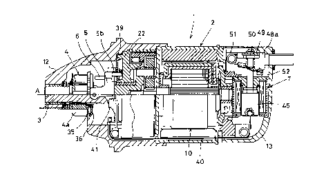
The starter of this embodiment, indicated at 1,
comprises a starter motor 2 which generates a rotating force
when supplied with electric power, an output shaft 3 disposed
coaxially with a rotating shaft of the starter motor 2, a
rotating force transfer means (to be described later) for
transmitting the rotating force of the starter motor 2 to the
output shaft 3, a pinion 4 fitted on the outer periphery of
the output shaft 3, a retreat restricting member 5 for
restricting the retreat of the pinion 4 after meshing of a
tooth portion 4a (hereinafter referred to as the pinion gear
4a) with a ring gear 100 of an engine (not shown), a rotation
restricting member 6 for restricting the rotation of the
pinion 4 after meshing of the pinion gear 4a with the ring
gear 100 and until advance by a predetermined distance, and a
magnet switch 7 disposed behind the starter motor 2.
(Starter Motor 2)
The starter motor 2 comprises a yoke 8, fixed poles 9,
-15-
21 76087
an armature 10, and brushes (not shown). The yoke 8, which is
provided in a cylindrical form, is held between a housing 12
and an end cover 13 together with a holder 11 which is
disposed on the rear end side (right end side in Fig. 1) of
the yoke 8.
The fixed poles 9, formed by permanent magnets for
example, are fixed to the inner peripheral surface of the yoke
8 and form a magnet field. As the fixed poles 9, field coils
which generate a magnet force when energized may be used in
place of permanent magnets.
The armature 10 comprises a shaft 14 serving as a
rotating shaft, a core 15 provided on the outer periphery of
the shaft 14, coils 16 mounted on the core 15, and a commuta-
tor 17 attached to the rear end face of the core 15. In the
armature 10, the shaft 14 is disposed behind and coaxially
with the output shaft 3, the front end portion of the shaft 14
is supported in a recess rotatably through a bearing 18 which
recess is formed in the rear end portion of the output shaft
3, and the rear end of the shaft 14 is supported by the holder
11 rotatably through a bearing 19.
The brushes (not shown) are held by the holder 11 and
are each urged to the commutator 17 by means of a spring (not
shown) incorporated in the end cover 13.
(Output Shaft 3)
The front end portion of the output shaft 3 is
supported rotatably by a bearing portion 12a of the housing
12, while the rear end portion thereof is supported rotatably
2l76o87
by a center case 22 (the stationary member in the present
invention) through a bearing 21. The rear end of the output
shaft 3 is provided integrally as a planet carrier 23 in a
planetary reduction gear mechanism (to be described later).
The center case 22 is fixed to the inner periphery on the rear
end side of the housing 12 and covers the outer periphery of
the rotating force transfer means.
(Rotating Force Transfer Means)
The rotating force transfer mechanism is composed of
a planetary gear reduction mechanism and a one-way clutch.
The planetary gear reduction mechanism is a reduction mecha-
nism for decreasing the rotational speed of the starter motor
2 and increasing the output torque of the same motor.
It is composed of a sun gear 24 formed on the
front-end outer periphery of the shaft 14, three planetary
gears 25 meshing with the sun gear 24, an internal gear 26
meshing with the planetary gears 25, and the planet carrier 23
referred to above. The three planetary gears 25 are each
supported by a pin 27 rotatably through a bearing 28, the pin
27 being fixed to the planet carrier 23. In the planetary
gear reduction mechanism, as the sun gear 24 rotates together
with the shaft 14, each planetary gear 25 meshing with both
sun gear 24 and internal gear 26 revolves in the same direc-
tion as the sun gear 24 while rotating on its own axis
(reverse to the rotation of the sun gear 24), and this
revolving force is transmitted to the planet carrier 23
through the pin 27, so that the output shaft 3 rotates.
-17-
~l76o8~
-
The one-way clutch supports the internal gear 26 in
the planetary gear reduction mechanism so as to be rotatable
only in one direction (the direction in which it rotates under
the rotation of the engine). The one-way clutch comprises an
outer 29, an inner 30, and rollers 31.
The outer 29 is formed in a cylindrical shape
integrally on the front side of the internal gear 26. The
inner 30 is formed integrally on the rear side of the center
case 22 and defines a roller housing (not shown) together with
the outer 29. The roller 31, which is accommodated in the
roller housing, locks the outer 29 and the inner 30 at the
time of transmitting the rotating force of the starter motor
2 to the output shaft 3.
(Pinion 4)
In the interior of the housing 12 the pinion 4 is
fitted through a helical spline onto the outer periphery of
the output shaft 3 in a position close to the front end of the
output shaft and is normally urged backward of the output
shaft 3 (rightward in Fig. 1) by means of a spring 32 disposed
on the front end side of the pinion 4. The spring 32 urges
the pinion 4 through a ring portion 33a of a shutter 33 which
is fitted on the outer periphery of the output shaft 3 in
front of the pinion 4. In interlock with the movement of the
pinion 4 the shutter 33 opens or closes an opening portion
(not shown) of the housing 12 which opening portion opens on
the ring gear side.
As shown in Figs. 3 and 7, on the rear end side of the
-18-
2176087
pinion 4 is integrally provided a rotation restricting plate
34 larger in outside diameter than the pinion 4 and having a
large number of recesses 34a formed in the outer periphery
thereof. The number of the recesses 34a is larger than the
number of teeth of the pinion gear 4a.
Further, on the rear end side of the rotation re-
stricting plate 34 is mounted a thrust ring 36 (the rotatable
member in the present invention) rotatably in the rotating
direction of the pinion 4 through a thrust bearing 35.
(Retreat Restricting Member 5)
As shown in Fig. 5, the retreat restricting member 5
comprises two side pieces 5a which are generally L-shaped in
side view, and a release bar 5b which provides a connection
between the two side pieces 5a. As shown in Figs. 3 and 7,
the retreat restricting member 5 is rotatably engaged around
a pair of pins 37 (a first abutting portion in the present
invention) as an axis center (see Fig. 4). The pins 37 are
biased to the side of a plate 39 attached to the front end of
the center case 22 by a spring 38 engaged with one of side
pieces 5a so that one end (bent portion 5c) of each side piece
5a abuts the plate 39 and the other end is fixed to the both
radial sides of the thrust ring 36. It is to be noted that
Fig . 3 shows a rest state (initial position) of the retreat
restricting member 5, and Fig. 7 shows a condition where the
retreat restricting memeber 5 moved to the retreat restricting
position of the pinion 4. Fig. 8 shows the state, viewed from
the side of the starter motor 2 as in Fig. 7, where the
--19--
21 76087
retreat restricting member 5 is restricting the retreat of the
pinion 4. The pins 37 are provided between a first and second
parallel lines 3b and 3c which are tangential to an outer
circumference of the helical spline 3a of the output shaft 3
and at positions opposing to each other relative to the output
shaft 3 as a center.
Each side piece 5a is provided with an engaging recess
5d (third abutting portion in the present invention, see Fig.
5) in a position between the bent portion 5c and the release
bar 5b, the recess 5d being engageable with an engaging
portion 6a (described later) of the rotation restricting
member 6.
One end of the spring 38 is engaged with the plate 39
(stationary member in the present invention), while the
opposite end thereof is engaged with the bent concave portion
of one side piece 5a. The spring 38 may be disposed on both
sides of the retreat restricting member 5. In other words,
there may be used an additional spring 38 for engagement with
the other side piece 5a. The retreat restricting member 5
constitutes an arm member in the present invention. Further,
the movable cylindrical member of the present invention is
comprised of the pinion 4 and the thrust ring 36 assembled to
the pinion 4 and the pins 37 provided on the thrust ring 36.
(Rotation Restricting Member 6)
The rotation restricting member 6 is, as shown in Fig.
6, constituted by winding a metallic bar so that two such
engaging portions 6a as referred to above are formed during
-20-
2I 76087
the winding and so that both end portions of the winding are
bent up at right angles in the same direction at radially
opposed positions. One end portion of the bar thus bent up
serves as a rotation restricting bar 6b which comes into
engagement with the recess 34a of the rotation restricting
plate 34 at the initial stage of operation of the starter 1 to
restrict the rotation of the pinion 4. At the other end
portion of the bar is formed a cord-like member engaging
portion 6c with which is engaged one end of a cord-like member
40 (connecting member in the present invention; see Fig. 1)
such as wire or the like and to which is transmitted the
operation of the magnet switch 7 through the cord-like member
40.
As shown in Fig. 1, the rotation restricting member 6
is accommodated in a space formed between the center case 22
and the plate 39 so that its both end portions and two
engaging portions 6a are positioned forward with respect to
the plate 39 so that it can move vertically (upward and
downward directions in Fig. 1) through the space. The
rotation restricting member 6 is normally urged upward (upward
in Fig. 1) by means of a return spring 41, and when the
attractive force of the magnet switch 7 is transmitted to the
cord-like member engaging portion 6c through the cord-like
member 40, the whole of the rotation restricting member 6
moves downward against the biasing force of the return spring
41, while when the magnet switch 7 is turned off and the
attracting force disappears, the whole of the rotation
-21-
21 76087
,.
restricting member 6 moves upward and returns to its initial
position (the position shown in Fig. 1) by virtue of the
return spring 41. The rotation restricting member 6 also
constitutes an arm position holding member in the present
invention).
(Magnet Switch 7)
As shown in Fig. 1, the magnet switch 7 is disposed
inside the end cover 13 while being held on the rear end side
of the holder 11 and is fixed so that its operating direction
intersects the shaft 14 of the starter motor 2.
The magnet switch 7 comprises switch cover 42, coil
43, stationary core 44, plunger 45, spring 46, and rod 47.
The switch cover 42 is formed by pressing a magnetic material
(e.g. iron) into a cup shape, and centrally of the bottom of
the cover is formed with an insertion hole for slidable inser-
tion therein of the plunger 45.
The coil 43 is connected to a vehicular battery (not
shown) through a vehicular starting switch (ignition switch;
not shown). When energized upon turning on of the starting
switch, the coil 43 generates an electromagnetic force. The
stationary core 44 is disposed on the upper end side of the
coil 43 and is fixed by caulking to an opening portion of the
switch cover 42.
The plunger 45, formed of a magnetic material (e.g.,
iron) and having a generally cylindrical shape, is disposed in
the hollow interior of the coil 43 in opposition to the
stationary core 44, and when the coil 43 is energized, the
-22-
2176087
plunger 45 is magnetized and attracted toward the stationary
core 44 (upward in Fig. 2). To the bottom of the plunger 45
is connected the other end of the cord-like member 40.
The spring 46 is interposed between the plunger 45 and
the stationary core 44 on the inner peripheral side of the
coil 43 and urges the plunger 45 downward (downward in Fig. 1)
with respect to the stationary core 44. That is, when the
coil 43 is deenergized, the plunger 45 which has been attract-
ed to the stationary core side against the biasing force of
the spring 46 is returned to its initial position (the
position shown in Fig. 1).
The rod 47, which is made of an insulating material
(e.g. resin), is fixed to the upper side of the plunger 45,
passes through the hollow interior of the coil 43, further
passes slidably through a through hole formed centrally in the
stationary core 44, and is projected upward.
(Contact Structure of the Starter Motor 2)
A contact structure of the starter motor comprises a
terminal bolt 48 attached to the end cover 13, a fixed contact
49 fixed to a head 48a of the terminal bolt 48, a main movable
contact 50 connected to a lead wire (not shown) of a positive
pole-side brush, and a secondary movable contact 52 connected
to the main movable contact 50 through a starting resistor 51.
The terminal bolt 48 is mounted in such a manner that
it extends through a bottom wall 13a of the end cover 13 and
its front-end side is exposed to the exterior of the end cover
42. The terminal bolt 48 is fixed to the end cover 13 by
-23-
21~6~8~7
tightening a washer 53 and is connected to a positive elec-
trode of the vehicular battery through a battery cable (not
shown).
Inside the end cover 13 the fixed contact 49 is fixed
to the head 48a of the terminal bolt 48 by welding or the
like.
The main movable contact 50 is disposed in opposition
to the fixed contact 49 and is slidably fitted on the rod 47
of the magnet switch 7.
The starting resistor 51 is formed of nickel for
example and is wound in the form of coil to impart resilience
thereto. One end of the starting resistor 51 is fixed to the
main movable contact 50 and the other end fixed to the
secondary movable contact 52.
The secondary movable contact 52 is disposed in
opposition to the head 48a of the terminal bolt 48. When the
magnet switch 7 is turned on to attract the plunger 45, the
secondary movable contact 52 abuts the bolt head 48a with
movement of the rod 47, while when the magnet switch 7 is
turned off, the contact 52 abuts the outer end face of the
stationary core 44 and turns conductive electrically (see Fig.
2).
The spacing between the secondary movable contact 52
and the head 48a of the terminal bolt 48 is set smaller than
the spacing between the main movable contact 50 and the fixed
contact 49. When the magnet switch 7 is turned on and the
plunger 45 attracted toward the stationary core 44, the
-24-
2176087
secondary movable contact 52 comes into abutment with the head
48a of the terminal bolt 48 before abutment of the main
movable contact 50 with the fixed contact 49, whereby the
battery voltage is applied to the armature 10 of the starter
motor 2 through the starting resistor 51.
(Operation of First Embodiment)
The operation of this embodiment will be described
below.
When the starting switch is turned on by a driver, the
coil 43 of the magnet switch 7 is energized and the plunger 45
is attracted toward the magnetized stationary core 44 against
the biasing force of the spring 46.
With such movement of the plunger 45, the cord-like
member 40 is pulled toward the magnet switch 7, so that the
rotation restricting member 6 moves downward through the space
portion, and the rotation restricting bar 6b comes into
engagement with a recess 34a formed on the outer periphery of
the rotation restricting plate 34 to restrict the rotation of
the pinion 4.
On the other hand, as the plunger 45 goes up, the
secondary movable contact 52 abuts the head 48a of the
terminal bolt 48 and the positive pole-side brush is supplied
with the electric power through the starting resistor 51,
whereby a low voltage is applied to the starter motor 2 to
start up the same motor, and the armature 10 starts rotating.
The rotation of the armature 10 is decelerated by the plane-
tary gear reduction mechanism and then transmitted to the
-25-
2176087
output shaft 3, causing the output shaft 3 to rotate. With
this rotation of the output shaft 3, the pinion 4 also tries
to rotate, but since the rotation of the pinion 4 is restrict-
ed by the rotation restricting bar 6b, the rotating force of
the output shaft 3 works on the pinion 4 as an axially
pushing-out thrust. As a result, the pinion 4 advances along
the helical spline with respect to the output shaft 3, thus
permitting the pinion gear 4a to come into mesh with the ring
gear 100.
On the other hand, with the advance motion of the
pinion 4, the retreat restricting member 5 is pulled by the
thrust ring 36, so that the bent portions 5c of the retreat
restricting member 5 get into the inside while sliding on the
plate 39, and as shown in Fig. 7 the whole of the retreat
restricting member 5 is raised up axially and is interposed
between the thrust ring 36 and the plate 39. In order that
the retreat restricting member 5 can return to its initial
position when the magnet switch 7 is turned off, the bent
portions 5c (abutments onto the plate 39) of the retreat
restricting member 5 are positioned outside an axis A passing
through the pin 37 (above the axis A in Fig. 2).
Upon complete meshing of the pinion gear 4a with the
ring gear 100, the front end of the rotation restricting bar
6b of the rotation restricting member 6 becomes disengaged
from the recess 34a of the rotation restricting plate 34 and
falls toward the rear end side of the thrust ring 36, thereby
releasing the rotation-restricted state of the pinion 4.
2176087
Further, after the engaging portions 6a of the
rotation restricting member 6 are raised up axially, they come
into engagement with the engaging recesses 5d of the retreat
restricting member 5, whereby the posture of the retreat
restricting member 5 is kept as it is. Thus, the rotation
restricting member 6 also serves as a posture holding means
for holding the posture of the retreat restricting member 5.
Thereafter, upon abutment of the main movable contact
50 with the fixed contact 49, the starting resistor 51 is
short-circuited and a rated voltage of the battery is applied
to the starter motor 2, thus causing high speed rotation of
the armature 10. The rotation of the armature 10 is transmit-
ted to the output shaft 3 through the planetary gear reduction
mechanism and the pinion 4 which has been released from the
rotation-restricted state rotates together with the output
shaft 3, causing the ring gear to rotate, whereby the engine
can be started up.
With the pinion 4 advanced and the pinion gear 4a
meshing with the ring gear 100, the biasing force of the
spring 32 disposed on the front-end side of the pinion 4
becomes large. When the pinion 4 is rotated by the ring gear
100 after start-up of the engine, the rotating force of the
engine works on the pinion retreating direction under the
action of the helical spline 3a. With these forces, the
pinion 4 tries to retreat with respect to the output shaft 4,
but the retreat restricting member 5 and the rotation re-
stricting member 6 can inhibit the retreat of the pinion
2176087
conjointly (that is, the rotation restricting member 6 holds
the posture of the retreat restricting member 5 located in its
retreat restricting position). Since the pair of side pieces
5a of the retreat restricting member 5 are in abutment with
the pins 37 fixed to the both sides of the thrust ring 36,
retreating of the pinion 4 is restricted.
Thereafter, when the starting switch is turned off to
stop the supply of electricity to the coil 43 of the magnet
switch 7, the coil 43 is deenergized, so that the plunger 45
which has been attracted toward the stationary core 44 is
returned to its initial position (moves downward in Fig. 1)
with the biasing force of the spring 46. As a result, the
pulling force for the rotation restricting member 6 through
the cord-like member 40 disappears and hence the rotation re-
stricting member 6 reverts to its initial position by virtue
of the return spring 41.
At this time, the engaging portions 6a of the rotation
restricting member 6 are disengaged from the engaging recesses
5d of the retreat restricting member 5 and the release bar 5b
is pushed upward by the rotation restricting bar 6b of the
rotation restricting member 6, so that the retreat restricting
member 5 rotates counterclockwise in Fig. 7 about the pin 37
fixed to the thrust ring 36 and is released from the retreat
restricting position for the pinion 4. As a result, the
pinion 4 which undergoes a retreating force from the ring gear
100 is returned to its rest state (the state shown in Figs. 1
and 3).
-28-
2176087
,~
(Advantages of First Embodiment~
According to the embodiment, the paired side pieces 5a
of the retreat restricting member 5 are positioned between the
first and second parallel lines 3b and 3c tangential to the
outer circumference of the helical spline of the output shaft
3 and at positions opposing to each other relative to the
output shaft 3 as the center. Further, the side pieces 5a
respectively abuts the pins 37 fixed to both radial sides of
the thrust spring 36 assembled to the pinion 4.
Compared with the conventional support structure at
one point, the moments exerting on the respective side pieces
5a which tends to incline the pinion 4 exert oppositely to
cancel out component forces. In particular, since the side
pieces 5a are positioned between the first and second parallel
lines 3b and 3c which are respectively tangential to the outer
circumference of the helical spline 3a of the output shaft 3,
the moments which exerts on the side pieces 5a can be reduced
greatly than in the case where the side pieces 5a are outside
the first and second tangential lines 3b and 3c. Consequent-
ly, it is possible to prevent the pinion 4 from tiltingrelative to the output shaft 3, thereby preventing deformation
of the retreat restricting member 5 and local wear or the
generation of noise between the pinion 4 and the side pieces
5a of the retreat restricting member 5 which are caused by
tilting of the pinion 4.
Moreover, since the retreat restricting member 5 comes
to assume the position between the thrust ring 36 and the
-29-
2176087
plate 39 with advance motion of the pinion 4 and the posture
of the retreat restricting member 5 is kept as it is by the
rotation restricting member 6, it is possible to inhibit the
retreat of the pinion 4. Therefore, the magnet switch 7 for
driving the rotation restricting member 6 through the
cord-like member 40 is required to generate only an attractive
force enough to move the rotation restricting member 6 to its
engaging position for holding the posture of the retreat
restricting member 5. That is, the magnet switch 7 does not
require a force (plunger attracting force) enough to overcome
the retreating force applied from the ring gear 100 to the
pinion 4, and it suffices to ensure the stroke of the plunger
45 by only the distance of movement of the rotation restrict-
ing member 6 from the outer peripheral side of the pinion 4 up
to the space position at the rear end. Thus, it becomes
possible to attain the reduction in size of the magnet switch
7.
Further, in particular, since the paired side pieces
5a of the retreat restricting member 5 respectively abut the
pair of pins 37 which are fixed to the both radial sides of
the thrust ring 36 assembled to the pinion 4 at two locations
radially symmetric relative to the axis center of the pinion
4, i~ is hig~ly possible to prevent the movable cylindrical
member (thrust ring 36 and the pins 37 on the thrust ring 36)
from tilting relative to the output shaft 3.
Further, since the retreat restricting member 5
supports at its side pieces 5a the thrust ring 36 mounted to
-30-
2176087
the pinion 4, the thrust ring 36 performs a relative rotation
with respect to the pinion 4 even upon rotation of the pinion
4, whereby the rotating force of the pinion 4 can be prevented
from being transmitted to the side pieces 5a of the retreat
restricting member 5. Consequently, it is possible to prevent
follow-up rotation of the side pieces 5a with rotation of the
pinion 4.
Moreover, since the operating posture of the retreat
restricting member 5 which maintains the advanced state of the
pinion 4 and restricts the retreat of the same pinion is
retained by the rotation restricting member 6 which consti-
tutes posture hoIding means, there is no retreat-restricted
state of the pinion 4 being released by the retreat restrict-
ing member 5 due to vibrations imposed on the starter 1 or the
like. Thus, the retreat restricting member 5 can maintain the
advanced state of the pinion 4 stably.
Further, since restricting the rotation of the pinion
4 and holding the posture of the retreat restricting member 5
can be constituted by the same material, there is neither
addition of component parts nor complication.
With the retreat restricting member 5 being raised in
the axial direction along with the advance movement of the
pinion 4, the bent portion 5c abutting the plate 39 moves to
slide over the plate 39 and enter into the axial direction
side of the output shaft 3. Accordingly, while the pinion 4
is at rest, the bent portion 5c of the retreat restricting
member 5 is located on the plate 39 and at the radial direc-
-31-
2176087
tion side of the output shaft 3. That is, the retreat
restricting member 5 is raised in the axial direction to be
placed between the pinion 4 and the center case 22, only when
the pinion 4 advances. As a result, the entire starter length
(axial length) at the rest condition of the pinion 4 can be
set short.
Moreover, since the rotation restricting member 6 is
connected through the cord-like member 40 to the magnet switch
7 and is moved to the position of abutment with the pinion 4,
the freedom of disposition of the magnet switch 7 relative to
the starter motor 2 increases (the magnet switch 7 may be
disposed in any position relative to the starter motor 2) and
the mountability on the engine is improved.
Further, since the spring 38 is hooked to both retreat
restricting member 5 and plate 39, the pinion 4 is pulled
backward (rightward in Fig. 1) through the retreat restricting
member 5. Therefore, the spring 38 can be used also as a
return spring for the pinion 4 and so it is possible to omit
the spring 32 disposed in front of the pinion 4.
Moreover, by a mere return of the rotation restricting
member 6 to its initial position under the biasing force of
the return spring 41 after turning-off of the magnet switch 7,
the engaging portions 6a of the rotation restricting member 6
and the engaging recesses 5d of the retreat restricting member
5 are disengaged from each other automatically, and the
rotation restricting bar 6b pushes up the release bar 5b, so
that the retreat restricting member 5 pivotally moves about
-32-
`` 217~6~
the pins 37 in a simple manner and can be disengaged from the
retreat restricting position for the pinion 4. Consequently,
the load on the return spring 41 (the releasing force for the
rotation restricting member 6) can be set low, and thus it is
possible to set small the attractive force of the magnet
switch 7 and attain the reduction in size.
Additionally, since in the first embodiment the
retreat restricting member 5 is mounted through the thrust
ring 36 to the pinion 4 slidingly in the radial direction and
is engaged rotatably with the pins 37 which are fixed to both
sides in the radial direction of the thrust ring 36, it is
possible to prevent follow-up rotation of the retreat re-
stricting member 5 with the pinion 4, and there is no possi-
bility of a deflected load being applied to the pinion 4.
Consequently, it is possible to prevent a local wear of the
pinion 4 and the rotation restricting member 6 and also
prevent the generation of noise induced by such local wear.
(Second Embodiment)
Figs. 9 and 10 are sectional views of a principal
portion of a starter according to a second embodiment of the
invention.
The starter of this embodiment, indicated at 1, is
different in the structure of the pinion retreat restricting
mechanism from that in the first embodiment, which difference
will be described below. The components having the same
functions, (or the same names), as in the first embodiment are
indicated by the same reference numerals as in the first
-33-
2176087
embodiment and explanations thereof will be omitted for
brevity.
A retreat restricting member 5 has a generally V-bent
shape of a rod-like member, as shown in Fig. 13, and is
disposed on both sides in the radial direction with respect to
an output shaft 3, with the end portion (first abutting
portion in the present invention) thereof being turnably
fitted in holes 36a (see Fig. 14) formed on side face of a
thrust ring 36. By means of springs 38 the retreat restrict-
ing members 5 are urged toward a plate 39 disposed at thefront end of a center case 22 and are pushed out to both
radially outer sides with respect to the plate 39 (see Fig.
12). That is, when the magnet switch 7 is kept turned off,
the pinion 4 is maintained in a rest state through the retreat
restricting members 5 thus urged by the springs 38 so as to
prevent the pinion 4 from rushing out due to vibrations of the
engine or the like.
As shown in Figs. 16 and 17, a rotation restricting
member 6 is formed by winding a metallic wire or the like so
that two pro~ecting portions 6d are formed in intermediate
positions and so that both end portions 6b and 6c are bent and
raised up at right angles in radially opposed positions and in
the same direction. One end portion 6b thus raised up comes
into engagement with a recess 34a of the rotation restricting
plate 34 at the initial stage of operation of the starter 1
and thus serves as a rotation restricting bar 6b for restrict-
ing the rotation of the pinion 4, while a cord-like member
-34-
217608~7
engaging portion 6c is formed at the other raised-up end
portion and one end of a cord-like member 40 is engaged
therewith. The operation of the magnet switch 7 is transmit-
ted to the rotation restricting member 6 through the cord-like
member 40.
When the pinion 4 advances and the retreat restricting
members 5 are pulled up axially, the two projecting portions
6d come into engagement with leg portions 5e of the retreat
restricting members 5 and thereby serve as stoppers to prevent
the retreat restricting member 5 from falling down (see Figs.
13 and 14).
In the plate 39 are formed sliding slots 39a for
sliding of the projecting portions 6d of the rotation re-
stricting member 6 and are also provided pivotal movement stop
portions 39b for the retreat restricting member 5 (see Figs.
11 and 13). The pivotal movement stop portions 39b are for
preventing follow-up rotation of the thrust ring 36 caused by
a frictional transfer of the pinion rotation to the thrust
ring 36. It is to be understood that Fig. 15 shows the
retreat restricted condition of the pinion 4 by the retreat
restricting member 5 as viewed from the side of the starter
motor 2 as in Fig. 13. The retreat restricting member 5 is
disposed (4 locations) between the first and second parallel
lines 3b and 3c tangential to the outer circumference of the
helical spline 3a of the output shaft 3 and at both radial
sides of the output shaft 3. The pinion 4 has the axis center
within a rectangle defined by the four locations. That is,
-35-
2176~87
the axis center of the pinion 4 is located within a polygonal
shape which is formed by connecting the first abutting
portions 5f abutting at three or more locations the thrust
ring 36 assembled to the pinion 4.
tOperation of Second Embodiment)
The operation of this embodiment will be described
below.
Like the first embodiment, when a starting switch is
turned on to operate a magnet switch 7, the rotation re-
stricting bar 6b of the rotation restricting member 6 comes
into engagement with a recess 34a of the rotation restricting
plate 34 to restrict the rotation of the pinion 4.
On the other hand, the output shaft 3 rotates under
the rotating force of the starter motor 2, whereby the
rotation-restricted pinion 4 advances along the helical spline
3a on the output shaft 3 and the pinion gear 4a come into mesh
with a ring gear, thus causing the engine to start up.
At this time, as shown in Fig. 14, the retreat
restricting member 5 is pulled by the thrust ring 36 with
advance motion of the pinion 4 and is thereby interposed
between the thrust ring 36 and the plate 39.
On the other hand, upon complete meshing of the pinion
gear 4a with the ring gear, the front end of the rotation
restricting bar 6b becomes disengaged from the recess 34a of
the rotation restricting plate 34 and falls into the rear end
side of the thrust ring 36, thereby releasing the rotation
restriction for the pinion 4. At the same time, the project-
-36-
2176087
ing portions 6d of the rotation restricting member 6 move
along the sliding slots 39a and come into engagement with the
leg portions 5e (pivotal movement support portion in the
present invention) of the retreat restricting members 5, thus
serving as stoppers to prevent the retreat restricting member
5 from falling down, whereby the posture of the retreat
restricting member 5 is kept as it is.
In this state, even when the pinion 4 is rotated by
the ring gear and a retreating force is exerted on the pinion,
it is possible to prevent retreat of the pinion 4 because by
posture of the retreat restricting members 5 interposed
between the thrust ring 36 and the plate 39 is retained by the
rotation restricting member 6.
Thereafter, when the starting switch is turned off,
the rotation restricting member 6 returns to its initial
position under the biasing force of a return spring 38,
whereby the projecting portions 6d of the rotation restricting
member 6 and the leg portions 5e of the retreat restricting
members 5 are disengaged from each other. As a result, the
pinion 4 is returned to its rest state (the state shown in
Figs. 9 and 12) together with the retreat restricting member
5.
(Advantages of Second Embodiment)
According to this embodiment, the same effects as in
the first embodiment can be attained. Particularly in this
embodiment, the end portion 5f engaged in the hole 36a of the
thrust ring 36 mounted on the pinion 4 abuts the thrust ring
-37-
2176087
36 at three or more locations around the axis center of the
pinion 4. Therefore, The pinion 4 is prevented from tilting
relative to the output shaft 3. Further, the following
effects can also be provided.
In the first embodiment the operating directions of
the retreat restricting member 5 and that of the rotation
restricting member 6 are the same with respect to the direc-
tion in which the retreating force of the pinion 4 is applied,
so a certain type of an engine may require increasing the
attractive force of the magnet switch 7 in proportion to the
retreating force of the pinion 4.
According to this embodiment, in contrast thereto,
since the operating directions of the retreat restricting
members 5 and that of the rotation restricting member 6 (the
operating direction of the projecting portions 6d) are
orthogonal to each other with respect to the direction in
which the retreating force of the pinion 4 is applied, it is
not necessary to increase the attracting force of the magnet
switch in proportion to the retreating force of the pinion 4.
This is suitable for the reduction in size of the magnet
switch.
- Moreover, the retreat restricting members 5 are
supported by the rotation restricting member 6 at the end
portion which on the counter-fulcrum side (i.e., opposite side
to one end portion with respect to the point of action)
opposite to the point of action on which the retreating force
of the pinion 4 exerts. That is, the retreat restricting
-38-
2176087
members 5 are supported at both ends by the center case 22 and
the rotation restricting member 6 relative to the retreating
force of the pinion 4 exerting on the point of action. As a
result, since the tretreat restricting members 5 can deform
(flex) against the retreating force of the pinion 4, the
members themself flex to provide a buffer effect when the
pinion 4 vibrates in the axial direction (back-and-forth
movement at the time of engine starting) and applies repeated
retreating forces to the retreat restricting members 5.
(Third Embodiment)
Fig. 18 is a side view of a pinion retreat restricting
mechanism according to a third embodiment of the invention.
A starter according to this embodiment is different in
the structure of the pinion retreat restricting mechanism from
the second embodiment, which difference will be described
below. The same components having the same functions (the
same names), as in the first and second embodiments are
indicated by the same reference numerals and explanations
thereof will be omitted for brevity.
A retreat restricting member 5 includes an annular
portion 5q (see Fig. 19) having a central circular hole 5f for
passing therethrough an output shaft 3, side wall portions 5r
bent at right angles to the annular portion 5q on both sides
of the annular portion 5q, and fulcrum portions 5i each
supported rotatably by a support pin 54 which is fixed to a
center case 22. The retreat restricting member 5 is mounted
by fitting the support pin 54 into a hole 5j (see Fig. 20)
-39-
2176087
formed in each fulcrum portion 5i and by fitting engaging pins
36b of thrust ring 36 into elongated holes 5k formed in the
side wall portions 5r. Thus, the retreat restricting member
5 is pivotable about the support pin 54.
The retreat restricting member 5 is urged toward a
plate 39 by means of a spring 38 fitted on the support pin 54.
More specifically, the spring 38 urges the pinion 4 backward
(toward the plate 39 through the retreat restricting member 5
to hold the pinion in a rest state and at the same time gives
aid to preventing jump-out of the pinion 4 after start-up of
the engine.
As shown in Fig. 21, the rotation restricting member
6 is formed by winding a metallic rod or the like in such a
manner that both end portions thereof are bent and raised up
at right angles in the same direction and in opposed positions
radially. One end portion thereof thus raised up comes into
engagement with a recess 34a of the rotation restricting plate
34 at the initial stage of operation of the starter and thus
serves as a rotation restricting bar 6b for restricting the
rotation of the pinion 4. With the other end portion of the
rotation restricting member 6 which portion serves as a
cord-like member engaging portion 6c there is engaged with one
end of a cord-like member 40. The operation of a magnet
switch is transmitted to the rotation restricting member 6
through the cord-like member 40. When the retreat restricting
member 5 is pulled up axially with advance motion of the
pinion 4, as shown in Fig. 22, the rotation restricting bar 6b
-40-
2176087
moves into the portion behind the annular portion 5q of the
retreat restricting member 5 and supports an end 5p (second
abutting portion in the present invention) of the annular
portion 5q, thereby holding the posture of the retreat
restricting member 5. In this embodiment, as in the first
embodiment, when the retreat of the pinion 4 is restricted,
the side wall portions 5r of the retreat restricting member 5
abut the thrust ring 36 of the pinion at the positions which
are between the first and second parallel tangential lines 3b
and 3c tangential to the outer circumference of the helical
spline 3a of the output shaft 3 and opposing each other with
respect to the output shaft 3.
(Operation of Third Embodiment)
The operation of this embodiment will be described
below.
Like the first and second embodiments, when a starting
switch is turned on to operate the magnet switch, the rotation
restricting bar 6b of the rotation restricting member 6 comes
into engagement with a recess 34a of the rotation restricting
plate 34 to restrict the rotation of the pinion 4.
On the other hand, as the output shaft 3 rotates under
the rotating force of the starter motor 2, the pinion 4 which
is in a rotation-restricted state advances along the helical
spline on the output shaft 3 and the pinion gear 4a comes into
mesh with the ring gear to start up the engine.
At this time,as shown in Fig. 22, with advance motion
of the pinion 4, the retreat restricting member 5 is pulled up
-41-
2176087
axially about the support pin 54 while the engaging pins 36b
of the thrust ring 36 and the elongated holes 5k formed in the
side wall portions 5r are engaged with each other.
On the other hand, upon complete meshing of the pinion
gear 4a with the ring gear, the front end of the rotation
restricting bar 6b becomes disengaged from the recess 34a of
the rotation restricting plate 34 and falls behind the rear
end of the thrust ring 36, thereby releasing the rotation
restriction for the pinion 4, and at the same time the front
end of the rotation restricting bar 6b supports the end 5p of
the retreat restricting member 5, whereby the posture of the
retreat restricting member 5 which has been pulled and raised
up axially by the thrust ring 36 is retained.
As a result, even when the pinion 4 is rotated by the
ring gear and a retreating force is exerted on the pinion 4,
the retreat of the pinion 4 can be inhibited by co-operation
of both retreat restricting member 5 and rotation restricting
member 6.
Thereafter, when the starting switch is turned off,
the rotation restricting member 6 is returned to its initial
position by the biasing force of a return spring (not shown),
whereby the front end of the rotation restricting bar 6b is
disengaged from the rear end of the retreat restricting member
5 and hence the pinion 4 is returned to its rest state (state
shown in Fig. 18) together with the retreat restricting member
5.
In this embodiment the retreat restricting member 5 is
-42-
2I 76087
-
mounted on the pinion 4 rotatably through thrust ring 36 and
the rotating force of the pinion 4 is not applied to the
rotation restricting bar 6b which supports the end 5p of the
retreat restricting member 5, so it is less likely that the
rotation restricting bar 6b will be bent or subject to wear.
Besides, since the side wall portions 5r of the
retreat restricting member 5 come into abutment with the rear
end face of the thrust ring 36 at both sides in the radial
direction, the pinion 4 is supported at two points. There-
fore, the pinion 4 does not tilt with respect to the output
shaft 3, thus ensuring a high reliability of the starter.
(Advantages of Third Embodiment)
According to this embodiment, in addition to the sameeffects as in the first embodiment mentioned above there are
attained the following effects and features.
Owing to the arrangement of the rotation restricting
member 6 constituting the posture holding means in the space
between the center cace 22 as the stationary member and the
retreat restricting member 5, the protruding portion 6d works
as a stop bar when the pinion 4 tends to retreat, thereby
preventing the pinion 4 from retreating.
The end portion of the retreat restricting member 5 on
the side opposite to the support portion side with respect to
the working points (the engaging points between the side wall
portions 5r and the thrust ring 36) to which the retreating
force of the pinion 4 is applied. That is, the retreat
restricting member 5 is supported at two points of both ends
-43-
2176087
against the retreating force of the pinion 4 applied to the
working points, thus permitting the retreat restricting member
5 to undergo an axial deformation (deflec- tion) against the
retreating force of the pinion 4. As a result, when the
pinion gear 4a flutters (moves back and forth in the axial
direction) at the time of start-up of the engine
after meshing of the pinion gear with the ring gear, the
force generated upon retreat of the pinion 4 can be absorbed
(buffered).
Further, the distance from the fulcrum portion 5i of
the retreat restricting member 5 to the end of annular portion
5q for abutment with the rotation restricting bar 6b can be
set longer than the distance from the fulcrum portion 5i to
each working point to which the retreating force of the pinion
4 is applied. Therefore, on the basis of the principle of the
lever, the force necessary for preventing the retreat of the
pinion 4 can be set lower than that received directly.
Consequently, for the rotation restricting bar portion 6b it
is possible to adopt a material of an appropriate strength
accordingly, in other words, an excessively high strength
material is not needed, whereby it is made possible to provide
the starter in low cost.
(Fourth Embodiment)
Fig. 23 is a sectional view showing an internal struc-
ture of a pinion 4 and components disposed thereabouts. A
rotation restricting member 6 is constructed in the same
manner as in the third embodiment.
-44-
21 76087
...
This embodiment shows an example of a structure
wherein a retreat restricting member 5 is interlocked with a
shutter 33.
The shutter 33 is for opening and closing an opening
(not shown) of a housing 12 in interlock with movement of the
pinion 4 which opening is formed on the ring gear side. As
shown in Fig. 25, the shutter 33 is provided with a cylindri-
cal portion 33a to be fitted on the outer periphery of an
output shaft 3, an open/close plate 33b formed in a flat plate
shape extending forward from the underside of the cylindrical
portion 33a, and two support arms 33c extending backward from
both right and left sides of the cylindrical portion 33a while
passing sideways of the pinion 4. Further, as shown in Fig.
24, each support arm 33c is provided at the rear end thereof
with a boss portion 33d extending toward the output shaft 3,
with an engaging pin 33e being press-fitted into the boss
portion 33d in such a manner that the front end of the
engaging pin 33e is pro~ecting toward the output shaft 3 from
the end face of the boss portion.
A rear wall surface of the shutter 33 where the
cylindrical portion 33a is formed is in abutment with the
front end face of the pinion 4, and in this state the shutter
33 is urged backward (rightward in Fig. 23) by means of a
spring 32 disposed between it and the housing 12. Therefore,
when the pinion 4 advances on the output shaft 3 during
operation of the starter, the shutter 33 moves forward against
the biasing force of the spring 32 while being pushed forward
-45-
2176087
by the pinion 4, and when the pinion 4 is released from its
retreat-restriced state, the shutter is pushed back (to its
initial position shown in Fig. 23) together with the pinion 4
by virtue of the spring 32.
The spring 32 is disposed on the outer periphery of
the output shaft 3, and one end thereof is engaged with a
stepped face formed in a bearing portion 12a of the housing
12, while the opposite end thereof is engaged with an annular
groove 33f (see Fig. 25) formed in the circumference of the
cylindrical portion 33a of the shutter 33.
The retreat restricting member 5 is formed in about
the same shape as in the third embodiment. Holes 5j formed in
fulcrum portions 5i are each fitted in a support pin 54 fixed
to a center case, and engaging pins 33e press-fitted in the
rear end portions of the support arms 33c of the shutter 33
are fitted in elongated holes 5k formed in side wall portions
5r. In this way the retreat restricting member 5 is mounted
and it is rotatable about the support pin 54.
A rotation restricting member 6 used in this embodi-
ment is formed generally in the same shape as in the third
embodiment. It has a rotation restricting bar 6b which comes
into engagement with a recess 34a of the rotation restricting
plate 34 in the initial stage of operation of the starter to
restrict the rotation of the pinion 4.
(Operation of Fourth Embodiment)
The operation of this embodiment will be described
below.
-46-
2176087
When a starting switch is turned on to operate a
magnet switch, the rotation restricting bar 6b of the rotation
restricting member 6 comes into engagement with a recess 34a
of the rotation restricting plate 34 to restrict the rotation
of the pinion 4.
On the other hand, as the output shaft 3 rotates under
the rotating force of the starter motor, the
rotation-restricted pinion 4 advances along the helical spline
on the output shaft 3 and the pinion gear 4a comes into mesh
with a ring gear to start up the engine.
At this time, the shutter 33 moves forward with
advance motion of the pinion 4, so that the retreat restrict-
ing member 5 is pulled up axially about the support pin 54
while the engaging pins 33e press-fitted in the rear end
portions of the support arms 33c and the elongated holes 5k
formed in the side wall portions 5r are engaged with each
other.
As to the rotation restricting member 6, the front end
of the rotation restricting bar 6b is disengaged from the
recess 34a of the rotation restricting plate 34 upon complete
mesh of the pinion gear 4a with the ring gear and falls toward
the rear end side of the thrust ring 36, so that as soon as
the pinion 4 is released from its rotation restricted state,
the front end of the rotation restricting bar 6b supports the
rear end of the retreat restricting member 5, whereby the
posture of the retreat restricting member 5 which has been
pulled and raised up in the axial direction by the shutter 33
-47-
2176087
is retained.
Therefore, even when the pinion 4 is rotated by the
ring gear and a retreating force is exerted on the pinion 4,
the retreat of the pinion can be inhibited by cooperation of
both retreat restricting member 5 and rotation restricting
member 6.
Thereafter, with the starting switch turned off, the
rotation restricting member 6 is returned to its initial
position by the biasing force of a return spring (not shown),
whereby the front end of the rotation restricting bar 6b is
disengaged from the rear end of the retreat restricting member
to release the retreat restriction of the pinion 4.
Consequently, the shutter 33 and the pinion 4 are pushed back
to their initial positions by virtue of the spring 32, whereby
the retreat restricting member 5 also reverts to its rest
state (the state shown in Fig. 23).
(Advantages of Fourth Embodiment)
According to the structure of this embodiment, since
the retreat restricting member 5 is connected to the shutter
33 which is a non-rotatable member and is thereby prevented
from follow-up rotation with the pinion 4, the rotating force
of the pinion is not applied to the rotation restricting bar
6b and hence it is unlikely that the bar 6b will be bent or
subject to wear. Besides, a deflected load is never imposed
on the pinion 4 through the retreat restricting member 5, so
that the pinion 4 does not tilt relative to the output shaft
3 and hence the reliability of the starter can be improved.
-48-
2176087
.
(Fifth Embodiment)
A fifth embodiment of the present invention will be
described below with reference to Figs. 26 to 30(a) through
30(c). A rotation restricting member 6 is constructed in the
same manner as in the third embodiment.
A starter according to this embodiment, indicated by
numeral 1, is different in the structure of the pinion retreat
restricting mechanism from the other embodiments, which
difference will be described below. The components having the
same functions, (the same names), as in the other embodiments
are indicated by the same reference numerals and explanations
thereof will be omitted for brevity.
Fig. 26 shows a retreated (rest) state of the pinion
and Fig. 27 shows an advanced (meshed) state of the pinion.
A rotation restricting member 6 is formed in about the
same shape as that in the third embodiment and is disposed
within a space formed between a center case 22 and a plate 39
so that a rotation restricting bar 5b and a cord-like member
engaging portion 6c are extended forward from the plate 39 so
that the rotation restricting member 6 can move vertically
(upward and downward directions in Fig. 26) through the space.
On the plate 39 is disposed a return spring 8A for urging the
rotation restricting member 6 to its initial position (upward
in Fig. 29). The return spring 8A comprises a coil portion 82
whose proximal portion 81 is retained in an obliquely downward
position on the front face of the plate 39, and an operating
end portion 83 extending at right angles to the axial direc-
-49-
2176087
,
tion from the front end of the coil portion 82 toward the
cord-like member engaging portion 6c. The operating end
portion 83 urges the cord-like engaging portion 6c nearly
upward by virtue of the repulsive force of the coil portion
82, whereby the rotation restricting member 6 is set to an
upper position (i.e. initial position) when electric power to
the magnet switch is kept off. On the other hand, when the
electric power is applied to the magnet switch, a plunger
causes the rotation restricting member 6 to move down through
the cord-like member 40.
Description is further directed to the retreat re-
stricting member 5 with reference to Figs. 26 and 30(a)
through 30(c).
As shown in Figs. 30(a) through 30(c), the retreat re-
stricting member 5 comprises fulcrum portions 5i each support-
ed pivotably by a support pin 54, a pivotable portion 51
extending above the support pin 54 from the fulcrum portions
5i, and side wall portions 5r formed separately on the right
and left sides of the pivotable portion 51. The retreat
restricting member 5 is formed by sheet metal working. The
fulcrum portions 5i are formed by cutting out a pair of right
and left portions integrally with the pivotable portion 51 and
then bending the right and left portions at right angles to
the the pivotable portion 51. The fulcrum portions 5i are
each formed with a hole 5j for insertion therethrough of a
support pin 54. Centrally of the pivotable portion 51 is
formed with a hole 5f through which is inserted the output
-50-
2176087
shaft 3. Further, a pair of side wall portions 5r are bent in
a direction opposite and orthogonal to the pivotable portion
51 from the right and left ends of the pivotable portion 51.
Abutment faces 5m of the paired side wall portions 5r can abut
the rear end face of thrust ring 36. An annular portion 5g
located above the pivotable portion 51 is bent slightly
backward with respect to the main portion of pivotable portion
51. The front end of the rotation restricting bar 6b comes
into contact with the rear end face of the annular portion 5g
to inhibit a backward pivotal motion of the annular portion.
Wound around the support pin 54 is a retreat restrict-
ing member urging spring 99 which serves as an urging means
for the retreat restricting member 5. A base end portion 99a
of the spring 99 is anchored to the plate 39, while an
operating end portion 99b thereof urges the pivotable plate
portion 51 of the retreat restricting member 5 forward,
whereby the side portions 5h of the retreat restricting member
5 are normally pressed against the rear end face of the thrust
ring 36.
As shown in Fig. 29, the plate 39 covers the opening
of a rotation restricting member guide slot 222 formed in the
center case 22 to prevent a ring portion 61 of the rotation
restricting member 6 from coming off the guide slot 222. A
large window 39c through which the rotation restricting bar 6b
pro~ects forward is formed centrally in the right and left
direction at the upper portion of the plate 39, while a small
window 39e through which the cord-like member engaging portion
-51-
2176087
6c projects forward is formed centrally in the right and left
direction at the lower portion of the plate 39. Into a hole
39d in Fig. 29 is inserted a through bolt (not shown) for
coupling together a housing 12 and an end cover 13 with a
starter motor 2 held therebetween.
Centrally in the transverse direction at the lower
portion of the center case 22 is provided with a roller
supporting wall 22a in a forwardly projecting state, and a
support pin 54 is press-fitted transversely into the roller
supporting wall 22a. A roller (not shown) for angular change
of the cord-like member 40 is supported rotatably by the
support pin 54.
(Operation of Fifth Embodiment)
The operation of this embodiment will be described
below.
When a starting switch is turned on and a magnet
switch 7 operates, the rotation restricting member 6 moves
downward and the rotation restricting bar 6b comes into
engagement with a recess 34a of the rotation restricting plate
34 for the pinion 4, whereby the rotation of the pinion 4 is
restricted.
On the other hand, as the output shaft 3 rotates under
the rotating force of the starter motor 2, the rotation-
restricted pinion 4 advances along the helical spline on the
output shaft 3 and the pinion gear 4a comes into mesh with a
ring gear. With advance motion of the pinion 4, the retreat
restricting member 5 moves pivotally about the support pin 54
-52-
2l76ns7
while the front end faces 5m of the side wall portions 5r are
kept in abutment with the thrust ring 36 under the biasing
force of the retreat restricting member urging spring 99.
When the pinion gear 4a advances by a predetermined
distance in mesh with the ring gear, the rotation restricting
bar 6b of the rotation restricting member 6 falls into the
space behind the thrust ring 36 to release the rotation-
restricted state of the pinion 4, and thereafter the front end
of the rotation restricting bar 6b comes into abutment with
the rear end face of the circular portion 5g (see Fig. 27).
The rotation of the output shaft 3 is transmitted through the
pinion 4 to the ring gear for start-up of the engine.
With the pinion 4 advanced and the pinion gear 4a
meshing with the ring gear, the urging force of the spring 32
disposed on the front end side of the pinion 4 becomes large.
Further, when the pinion 4 is rotated by the ring gear after
start-up of the engine, the rotating force of the engine works
on the direction to retreat the pinion 4 under the action of
the helical spline, so that the pinion 4 tends to retreat with
respect to the output shaft 3. As mentioned above, however,
the retreat of the pinion 4 is restricted by the rotation
restricting member 6 through the retreat restricting member 5
which is in abutment at the two abutment faces 5m with the
thrust ring 36 on the pinion 4, and thus disengagement thereof
from the ring gear is prevented.
Thereafter, when the starting switch is turned off,
the rotation restricting member 6 returns to its initial
-53-
2176087
position (see Fig. 26) by virtue of the return spring 8A. As
a result, the pinion 4 which undergoes a retreating force from
the ring gear moves back to its initial position (see Fig.
26).
In this embodiment there can be attained the same
effects as in the third embodiment.
(Sixth Embodiment)
A sixth embodiment of the present invention will be
described below with reference to Figs. 31 to 35. A rotation
restricting member 6 is constructed in the same manner as in
the third embodiment.
The sixth embodiment is different from the fifth
embodiment in the shape of a retreat restricting member 5 and
that of a thrust ring 36 in the pinion retreat restricting
mechanism, which difference will be described below. The
components having the same functions, (the same names), as in
the other embodiments are indicated by the same reference
numerals and explanations thereof will be omitted for brevity.
As shown in Figs. 32(a) and 32(b), the retreat re-
stricting member 5 (arm member in the present invention) is
composed of support portions 5i each supported pivotably by a
support pin 54, a pivotable member 51 extending above the
support pin 54 from the support portions 5i, a pair of side
portions 5h provided integrally with the pivotable member 51
and extending further upward from the pivotable member 51, a
pair of bent portions 5n which are formed respectively on the
paired side portions 5h and bent oppositely to the pinion
-54-
2176tl87
side, and an annular portion 5g which connects the paired side
portions 5h.
The paired side portions 5h can abut the rear end
faces of thrust ring 36. The front end of the rotation
restricting bar 6b of the rotation restricting member 6 comes
into contact with the rear end face of the annular portion 5g
to inhibit a backward pivotal motion of the annular portion.
The thrust ring 36 used in this embodiment is made up
of a fixed portion 36b which is engaged rotatably relative to
the pinion 4 and axially movably in an integral manner through
a thrust bearing 35, a pair of projecting portions 36c (first
projecting portion in the present invention) projecting from
the fixed portion 36b, and a pair of holding portions 36d
(second projecting portion in the present invention) respec-
tively projecting radially inwardly from the paired projecting
portions 36c toward the axis center of the pinion 4 to hold
the paired side portions 5h of the retreat restricting member
5. In the space defined by the fixed portion 36b, paired
projecting portions 36c and paired engaging portions 36d,
disposed are the paired side portions 5h of the retreat
restricting member 5 so that the retreat restricting member 5
moves through the space as the pinion 4 moves on the output
shaft (not shown).
(Operation of Sixth Embodiment)
The following description is now provided about the
operation of this embodiment.
With a starting switch turned on to operate the magnet
-55-
2I 7608 7
switch (not shown), the rotation restricting member 6 is moved
downward by a cord-like member (not shown) engaged with the
cord-like member engaging portion 6c of the rotation restrict-
ing member 6, and the rotation restricting bar 6b comes into
engagement with a recess 34a of the rotation restricting plate
34 to restrict the rotation of the pinion 4.
On the other hand, when the output shaft rotates under
the rotating force of the starter motor (not shown), the
pinion 4 now in a rotation-restricted state advances along the
helical spline on the output shaft and the pinion gear 4a
comes into mesh with the ring gear (not shown). With the
advance motion of the pinion 4 the retreat restricting member
5 moves within the space surrounded by the fixed member 36b,
paired projecting portions 36c and paired engaging portions
36d of the thrust ring 36, and the retreat restricting member
5 moves pivotally about the support pin 54 while abutting the
paired engaging portions 36d of the thrust ring 36, whereby
the retreat restricting member 5 is pulled toward the pinion
4. When the pinion gear 4a has advanced by a predetermined
distance in mesh with the ring gear, the rotation restricting
bar 6b of the rotation restricting member 6 falls into the
space located behind the thrust ring 36 to release the
rotation-restricted state of the pinion 4. Thereafter, the
front end of the rotation restricting bar 6b comes into
abutment with the rear end face of the annular portion 5g of
the retreat restricting member 5 (see Fig. 34). Then, the
rotation of the output shaft is transmitted through the pinion
-56-
2176087
4 to the ring gear to start up the engine.
With the pinion 4 advanced and the pinion gear 4a
meshing with the ring gear, the urging force of a spring
disposed on the front end side of the pinion becomes large.
Further, when the pinion 4 is rotated by the ring gear after
start-up of the engine, the rotating force of the engine works
on the direction to retreat the pinion 4 under the action of
the helical spline, so that the pinion 4 tends to retreat with
respect to the output shaft. However, as noted previously,
the retreat of the pinion 4 is restricted by the rotation
restricting member 6 through the retreat restricting member 5
which is in abutment at the two abutment faces 5m with the
thrust ring 36 on the pinion 4, and thus the disengagement
thereof from the ring gear is prevented (see Figs. 34 and 35).
It is to be noted that Fig. 35 shows the state in which the
retreat restricting member 5 is restricting the retreat of
pinion 4, as viewed from the side of starter motor 2 as in
Fig. 34. The abutting face 5m (first abutting portion in the
present invention) is in abutment with the thrust ring 36 at
positions which are between the first and second parallel
tangential lines 3b and 3c tangential to the outer circumfer-
ence of the helical spline 3a of the output shaft 3 and
opposing to each other with respect to the output shaft 3.
Thereafter, when the starting switch is turned off,
the rotation restricting member 6 returns to its initial
position (see Fig. 31) by virtue of a return spring (not
shown) engaged with the cord-like member engaging portion 6c
-57-
2I 76087
of the rotation restricting member 6. As a result, the pinion
4 which undergoes a retreating force from the ring gear
retreats to its initial position (see Fig. 31).
(Advantages of Sixth Embodiment)
5In this embodiment there can be obtained the same
effects as in the fifth embodiment.
Further, with movement of the pinion 4 the rotation
restricting member 6 can move generally radially while
supported axially within the holding portions 36d of the
10thrust ring 36 mounted on the pinion 4. Therefore, for moving
to a position for restricting the retreat of the pinion 4, it
is not necessary to use any separate member for moving
together with the pinion 4. As a result, with a simple struc-
ture it is possible to move the rotation restricting member 6
15to the position for restricting the retreat of the pinion 4.
Furthermore, the thrust ring 36 has the paired
projecting portions 36c respectively projecting from the fixed
portion 36b to the opposite side of the pinion 4, and the
paired engaging portions 36d respectively projecting radially
20inwardly from the paired projecting portions 36c toward the
axis center of the pinion 4. Therefore, the retreat restrict-
ing member 5 while being kept axially supported can move in a
generally radial direction within the space formed by the
holding portions 36c and 36d of the thrust ring 36 and drive
25easily the rotation restricting member 6 to the position for
restricting the retreat of the pinion 4.
The rotation restricting member 6 can be mounted by
-58-
2176087
simply being inserted (slided) into the space.
Moreover, the paired bent portions 5n which are bent
toward the opposite side of the pinion 4 are provided on the
paired side portions 5h respectively extending from the
support portion 5i, so that the bent portion 5n works as the
abutting face 5m relative to the pinion 4. Therefore, even
when the inclination of the retreat restricting member 5
relative to the center case 22 is not fixed, the paired bent
portions 5n abut the pinion 4 in a generally straight line
and, as a result, restriction on the retreat of the pinion can
be performed stably.
[Modifications]
Although in each of the above-described embodiments
the rotation restricting member 6 is driven by the magnet
switch 7 through the cord-like member 40, a small-sized motor
may be used for the same purpose in place of the magnet switch
7. Further, the connecting member need not be the cord-like
member but may be a rod-like member such as a lever or link
mechanism.
Although in each of the above embodiments the thrust
ring 36 is supported at two points by the retreat restricting
member 5, there may be adopted a three- or more-point support
structure. In this case, however, in order to prevent tilting
of the pinion 4 relative to the output shaft 3, it is neces-
sary that the axis of the pinion be present within a polygon
formed by connecting the support points.
Although the retreat restricting member 5 obtained by
-59-
2176087
..
sheet metal working is used in each of the above embodiments,
there may be used a resin molded product or the like.
Although in each of the above-described first to
fourth embodiments the retreat restricting member 5 and the
thrust ring 36 are connected by a coupling structure, both may
be attracted together using a magnet or the like and be
allowed to slide.
According to the structure of the starter 1 described
in each of the above embodiments, only the pinion 4 advances
with respect to the output shaft 3, there may be adopted a
structure wherein a one-way clutch (the movable cylindrical
member in the present invention) is helical-splined in the
outer periphery of the output shaft 3 and the pinion 4 is
integrally provided on the front-end side of the one-way
clutch.
Each starter 1 described hereinabove is so constructed
as that the pinion 4 is advanced by an operation of the
helical spline 3a on the output shaft and the rotating force
of the starter motor 2 while restricting the rotation of
pinion 4 formed with the pinion gear 4a. It is however
possible to use the pinion retreat restricting mechanism
according to the invention in the inertia engagement type
starters in which a pinion is advanced at the rise of starter
motor rotation by the use of the inertia of pinion.
Further, although in each of the above-described
second to sixth embodiments the moving direction of the
retreat restricting member 5 and the operating direction of
-60-
2 I 76 0 87
the rotation restricting member 6 as the posture holding means
are nearly orthogonal to each other, both directions are not
limited to such orthogonal directions. It is possible that if
both directions are not the same direction, the load imposed
on the posture holding means becomes a component of force and
hence smaller than in direct drive in the same direction and
that the force generated from the drive source (e.g. electro-
magnet switch) can be diminished accordingly (of course, in
the case where both directions are orthogonal to each other,
the component of force is zero and no force is exerted on the
drive source).
The present invention having been described above is
not limited to the disclosed embodiments but may be modified
further without departing from the spirit and scope of the
invnetion.
-61-