Language selection

Search

Patent 2176280 Summary

Third-party information liability

Some of the information on this Web page has been provided by external sources. The Government of Canada is not responsible for the accuracy, reliability or currency of the information supplied by external sources. Users wishing to rely upon this information should consult directly with the source of the information. Content provided by external sources is not subject to official languages, privacy and accessibility requirements.

Claims and Abstract availability

Any discrepancies in the text and image of the Claims and Abstract are due to differing posting times. Text of the Claims and Abstract are posted:

  • At the time the application is open to public inspection;
  • At the time of issue of the patent (grant).
(12) Patent: (11) CA 2176280
(54) English Title: IMPROVEMENT IN REVERSIBLE REARVIEW MIRROR
(54) French Title: RETROVISEUR REVERSIBLE AMELIORE
Status: Expired and beyond the Period of Reversal
Bibliographic Data
(51) International Patent Classification (IPC):
  • B60R 1/06 (2006.01)
(72) Inventors :
  • GORDON, PAULO ALEXANDRE (Brazil)
(73) Owners :
  • METAGAL INDUSTRIA E COMERCIO LTDA.
(71) Applicants :
  • METAGAL INDUSTRIA E COMERCIO LTDA. (Brazil)
(74) Agent: CASSAN MACLEAN
(74) Associate agent:
(45) Issued: 2006-07-25
(22) Filed Date: 1996-05-10
(41) Open to Public Inspection: 1997-04-28
Examination requested: 2003-05-12
Availability of licence: N/A
Dedicated to the Public: N/A
(25) Language of filing: English

Patent Cooperation Treaty (PCT): No

(30) Application Priority Data:
Application No. Country/Territory Date
PI 9504888-0 (Brazil) 1995-10-27

Abstracts

English Abstract


The reversible rearview mirror has a mirror plate (1); a housing (2) which
houses the
mirror plate, both the mirror (1) and the housing (2) being symmetrical with
respect to a
horizontal axis (X); a supporting member (3) which is semirigid so as to be
bendable
when its ends are pressed toward each other in an axial direction; and a base
(6) fixed to
a vehicle body and on which the supporting member (3) is pivotally mounted and
an
attachment device for assembling and attaching the housing (2) to the
supporting member
(3) which is provided between the housing (2) and the supporting member (3).
The
attachment device includes two L-shaped clamps (4) which extend
perpendicularly from
respective outside regions of a lateral portion (10) of the supporting member
(3) which
receives the housing (2); and respective grooves (5) provided in a lateral
portion (11) of
the housing (2), adjacent to the lateral portion (10) of the supporting member
(3), which
receive the respective L-shaped clamps (4).


Claims

Note: Claims are shown in the official language in which they were submitted.

WHAT IS CLAIMED IS:
1. ~A reversible rearview mirror, comprising a mirror plate; a housing,
housing
the mirror plate and having a lateral portion, both the mirror plate and the
housing being
symmetrical with respect to a horizontal axis; a resilient housing supporting
member
having supporting member ends and a lateral portion and being bendable when
said
supporting member ends are pressed toward each other in an axial direction,
the lateral
portion of the supporting member being shaped to engage with the lateral
portion of the
housing when the supporting member is assembled with the housing; a base on
which
said supporting member is pivotally mounted and which is fixed to a vehicle
body; and
attachment means for assembling and attaching the supporting member to the
housing,
wherein said attachment means is arranged between the housing and the
supporting member and comprises at least two L-shaped clamps and respective
grooves
provided in the lateral portion of the housing in which said at least two L-
shaped clamps
engage, each of said at least two L-shaped clamps have free ends and extend
perpendicularly from the lateral portion of the supporting member, said at
least two L-
shaped clamps are arranged in longitudinal alignment on said lateral portion
and with the
free ends thereof facing in opposite directions with respect to each other and
in
substantially parallel directions and toward the respective closest supporting
member
ends of the supporting member; and the respective grooves are provided in the
lateral
portion of the housing in a longitudinal alignment and positioned so as to
receive said at
least two L-shaped clamps, and each of said at least two L-shaped clamps has a
longer
leg extending from the lateral portion of the supporting member and a shorter
leg
connected to the longer leg, and said at least two L-shaped clamps engage
themselves on
opposite ends of said grooves closest to respective opposite ends of the
lateral portion of
the housing so that the longer legs of said at least two L-shaped clamps pass
through the
respective grooves and press against transverse edges of said grooves and the
shorter legs
of said L-shaped clamps press against internal surface regions of the housing
adjacent to
said ends of said grooves so as to press the lateral portion of the housing
against the
lateral portion of the supporting member.
-5-

2. The reversible rearview mirror as defined in claim 1, wherein the
supporting
member has a curved shape to facilitate bending of said supporting member when
said
supporting member ends of said supporting member are pressed and said
supporting
member comprises a body with a substantially elliptical cross-section and said
lateral
portion of the supporting member has a concave surface facing said housing and
said
housing has a corresponding surface fitting said concave surface of said
lateral portion
and said at least two L-shaped clamps are located at opposite ends of said
concave
surface; and further comprising two other auxiliary L-shaped clamps located in
an
intermediate position on said concave surface of the lateral portion of the
supporting
member and arranged in a transverse alignment with respect to the longitudinal
alignment of said at least two L-shaped clamps and respective grooves provided
in the
lateral portion of the housing in which said two other auxiliary L-shaped
clamps engage;
and wherein said supporting member is provided with a seat in a lower
supporting
member end of said supporting member and said base is provided with a ball
fitting in
said seat to form a ball joint for pivotal mounting of the supporting member
on the base,
and the lateral portion of the housing is slightly recessed from an outside
surface of the
housing and has a shape substantially corresponding to that of the supporting
member so
as to be ready to receive said member so that a convex outside surface of the
supporting
member is continuously connected with the outside surface of the housing.
-6-

Description

Note: Descriptions are shown in the official language in which they were submitted.


CA 02176280 1996-05-29
1
Descriptive report for the patent of Invention in respect to
Improvement in Reversible Rearview Mirror.
This patent has as purpose an outside rearview mirror,
part of automotive vehicle accessories field, and which has
received an improvement in order to simplify its construction
and use, when comparing with similar ones.
outside rearvisaw mirrors of reversible type have
already been known in the art, namely, those which may be used
indistinctly on the left or can the right side of the vehicle,
which comprise basically a mirror plate; a hous:i.ng which
contains said mirror plate, both symmetrical to the horizontal
axis; a rigid rod to which the housing .is attached by bolts and
clamps; and a base in which the rigid rod i.s affixed in a pivot
joint, and which is connected to the vehicle body.
The rigid rods are normally made of thermoplastic
material, and between said rods and the housings there is at
least one clamp which locks the housing-mirror set i.n a given
rotation position, and one or more bolts which. assure the
fastening of the set.
Even considering the wide use and high efficiency of
the outside rearview mirrors which use the above mentioned
construction, there are some inconveniences which may be
attributed to them, such as the high complexity of the
fastening means used between the housing and the r:i.gid rod,
which create difficulties at the assembly :line, a fact which
is undesirable.
1

CA 02176280 1996-05-29
Another problem is related to a certain degree of
difficulty for the user when performing the reversal, which is
also an undesirable fact.
Considering said problems, and aiming the elimination
of them, the improvement, object of t.hi.s patent of invention,
for the reversible outside rearv:~.ew mirror. was deve7.oped, the
construction, operation and advantages of which in respect to
the usual ones will become clear from the following detailed
description and the attached drawingd> where:
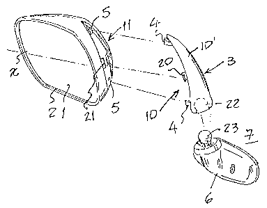
Figure 1 is a perspective view of the mirror, showing
the constitutive parts i.n separate;
Figure 2 shows the assembled mirror, in a view along
the plane which passes between the housing and the housing
supporting rad, with partial sections for a better
understanding, and assembled for left side use;
Figure 3 shows the same figure, but with detailed
indication on how the assembly or disassembly of the housing
and rod is made; and
Figure 4 shows the mirror assembled for right side use.
Tn accordanc:e with what is shown by the above listed
figure, the reversible outside rearvi.e.w mirror objects of this
patent comprises substantially; a set of mirror plate 1; a
housing 2 which houses the mirror plate, both of them, the
mirror 1 and the housing 2 being symmetrical in respect to an
horizontal geometric axis "X"; a housing 1 supporting rod 3:
assembling and fixing means ~-a located between the housing 2
and the rod 3; and a base 6 in which. the supporting rod ~ is
pivoted, and which is fixed to the vehicle body 7; said housing
2

CA 02176280 1996-05-29
~::. , w.a _. , ..1
2, the supporting rod 3 and the base 6 are made of an
appropriate thermoplastic material;
zn the present improvement, the supporting rod 3 is
semi-rigid, in such a way that :z.t bends when its ends are
pressed one against the>. other, in a direction substantially
axial to the rod: and the assembly/fixing means 4-5 between the
housing 2 and the supporting rod 3 comprise, at least two "L"
profile clamps 4 which protrude perpendicularly from the
respective outside portion of the lateral 10 of the supporting
rod 3 which receives the housing 2; said clamps are arranged
in longitudinal alignment on said lateral 10 and with the free
ends turned towards the opposite direction, one in x.~espect to
the other and in substantially para:~le:~.. directions of the
corresponding ends closest to the supporting rod 3 ; and the
respective grooves 5 made in the lateral 11 of the rrousing 2,
adjacent to the lateral 10 of the supporting rod 3, arranged
in a longitudinal alignment an said lateral of the housing and
receivers for the "L"" shaped clamps 4, which connect themselves
in their opposite ends, closest to the lateral ends of the
housing 11, in such a w<~y that the a.onger legs :12 of said "L"
shaped clamps 4, which protrude from the lateral 10 of the
supporting rod 3, pass through the respective grooves 5
remaining pressed against the transversal edges of said
grooves, and the shorter .legs 13 of said "L" shaped clamps 4
remain pressed against the internal surface regions of the
housing 2 , adj acent to the ends o:~ the same grooves 5 , pressing
the lateral 11 of the housing 2 against the lateral 10 of the
supporting rod 3, therefore making the whole set stable.
3

CA 02176280 1996-05-29
~ .r ~ r,
In this way, when the rearview mirror is assembled
(Fig. 2), the "L" shaped clamps 4 of the supporting rod 3
remain connected to the respective grooves __°i of the housing 2,
in such a way that the edges of the longer legs 12 of said
clamps remain pressed against the outside transversal edges of
the grooves 5 and the edges o:f the shorter legs 1.3 of said
clamps remain pressed against the internal surface of the
housing 2, pressing the lateral 10 and 11 of the supporting rod
3 and the housing 2 one against the other, therefore making the
whole set stable.
When the mirror should be disassembled to have its
position changed, as an example:, from the right side (Fig. 2)
to the left side (Fig. 4) , the ends of the supporting rod 3 are
pressed one against the other (Fig. ~)~ when the opposite
forces "F" and "F"' will force the rc~r~ to bend in its middle
region "M", and the "L" shaped clamps ~ to take a new position
in which they may be diacannected from the respective grooves
5, therefore allowing the supporting rod 3 to be disassembled
from the housing 2.
Then, the housing 2 and mirror 1 set is turned about
the horizontal "X" and the vertical. ax:~.s by 180°,, and the
supporting rod 3 is again pressed with the "L" shad>ed clamps
4 becoming connected to the inverted grooves 5, namely, an "L"
shaped clamp 4 enters into a groove a which had been priory
connected to another "L" shaped clamp 4 , and the supporting rod
3 is released, in such <~ way that the "L" shaped clamps 4 are
again pressed against the outs:i.de transversal edges of the
grooves 5 and the inner surface of the housing, due to the
4

CA 02176280 1996-05-29
' ~~'
t ~r ~~;
elasticity of the material used for the make the supporting rod
3, therefore fixing the set in its new position.
In a preferred configuration, as shown in the figures,
the supporting rod 3 presents a curved shape, in order to
facilitate its bending, when pressed from its ends. 'therefore,
said supporting rod 3 is semirigid and comprises a plate with
its profile being substantially elliptic, with surface 10 which
is turned towards the concave housing 2: said concave surface
has in its ends the "L" shaped clamps 4 and, in an
10 intermediate level, said surface has two other auxiliary "L"
shaped clamps 20,. located in a c:rassed transversal alignment
in respect to the longitudinal alignment of said clamps, which
connect themselves to t:he respective grooves 21 made in the
lateral 11 of the housing 2 and the Lower end of said rod
provides the seat 22, which connects with ball point 23
provided in the base 6.
The housing 2 has a slightly recessed lateral 11 where
the grooves 5 and 21 are provided, with the profiles
substantially equal to the supporting rods 3 and ready to
receive said rod, in such a way that the convex outside surface
10' of the mentioned supporting rod 3 is continuously connected
with the outside surface of the housing 2.
Within the above described basics conception, the
reversible outside rearview mirror :may be changed i.n respect
to materials, configurations, dimensions, colors, fin:i.shing and
others, without avoiding the protection of the patent.
5

Representative Drawing
A single figure which represents the drawing illustrating the invention.
Administrative Status

2024-08-01:As part of the Next Generation Patents (NGP) transition, the Canadian Patents Database (CPD) now contains a more detailed Event History, which replicates the Event Log of our new back-office solution.

Please note that "Inactive:" events refers to events no longer in use in our new back-office solution.

For a clearer understanding of the status of the application/patent presented on this page, the site Disclaimer , as well as the definitions for Patent , Event History , Maintenance Fee  and Payment History  should be consulted.

Event History

Description Date
Time Limit for Reversal Expired 2012-05-10
Letter Sent 2011-05-10
Grant by Issuance 2006-07-25
Inactive: Cover page published 2006-07-24
Inactive: Final fee received 2006-04-03
Pre-grant 2006-04-03
Notice of Allowance is Issued 2005-12-06
Letter Sent 2005-12-06
Notice of Allowance is Issued 2005-12-06
Inactive: Approved for allowance (AFA) 2005-11-22
Amendment Received - Voluntary Amendment 2005-11-03
Inactive: S.30(2) Rules - Examiner requisition 2005-05-03
Amendment Received - Voluntary Amendment 2003-09-19
Inactive: Application prosecuted on TS as of Log entry date 2003-05-27
Letter Sent 2003-05-27
Inactive: Status info is complete as of Log entry date 2003-05-27
All Requirements for Examination Determined Compliant 2003-05-12
Request for Examination Requirements Determined Compliant 2003-05-12
Application Published (Open to Public Inspection) 1997-04-28

Abandonment History

There is no abandonment history.

Maintenance Fee

The last payment was received on 2006-05-09

Note : If the full payment has not been received on or before the date indicated, a further fee may be required which may be one of the following

  • the reinstatement fee;
  • the late payment fee; or
  • additional fee to reverse deemed expiry.

Please refer to the CIPO Patent Fees web page to see all current fee amounts.

Owners on Record

Note: Records showing the ownership history in alphabetical order.

Current Owners on Record
METAGAL INDUSTRIA E COMERCIO LTDA.
Past Owners on Record
PAULO ALEXANDRE GORDON
Past Owners that do not appear in the "Owners on Record" listing will appear in other documentation within the application.
Documents

To view selected files, please enter reCAPTCHA code :


To view images, click a link in the Document Description column. To download the documents, select one or more checkboxes in the first column and then click the "Download Selected in PDF format (Zip Archive)" or the "Download Selected as Single PDF" button.

List of published and non-published patent-specific documents on the CPD .

If you have any difficulty accessing content, you can call the Client Service Centre at 1-866-997-1936 or send them an e-mail at CIPO Client Service Centre.


Document
Description 
Date
(yyyy-mm-dd) 
Number of pages   Size of Image (KB) 
Representative drawing 1997-11-17 1 11
Description 1996-05-29 5 302
Abstract 1996-05-29 1 46
Claims 1996-05-29 3 140
Cover Page 1996-05-10 1 16
Abstract 1996-05-10 1 27
Description 1996-05-10 3 131
Claims 1996-05-10 2 75
Drawings 1996-05-10 2 41
Cover Page 1998-07-08 1 16
Abstract 2005-11-03 1 26
Claims 2005-11-03 2 101
Representative drawing 2005-11-18 1 10
Cover Page 2006-06-29 1 44
Reminder of maintenance fee due 1998-01-21 1 111
Reminder - Request for Examination 2003-01-13 1 112
Acknowledgement of Request for Examination 2003-05-27 1 174
Commissioner's Notice - Application Found Allowable 2005-12-06 1 161
Maintenance Fee Notice 2011-06-21 1 171
Correspondence 1996-05-29 9 458
Fees 2000-05-08 1 44
Fees 2001-05-03 1 32
Correspondence 2006-04-03 1 37