Language selection

Search

Patent 2176428 Summary

Third-party information liability

Some of the information on this Web page has been provided by external sources. The Government of Canada is not responsible for the accuracy, reliability or currency of the information supplied by external sources. Users wishing to rely upon this information should consult directly with the source of the information. Content provided by external sources is not subject to official languages, privacy and accessibility requirements.

Claims and Abstract availability

Any discrepancies in the text and image of the Claims and Abstract are due to differing posting times. Text of the Claims and Abstract are posted:

  • At the time the application is open to public inspection;
  • At the time of issue of the patent (grant).
(12) Patent Application: (11) CA 2176428
(54) English Title: ADJUSTABLE GUARD ARRANGEMENT FOR POWER TOOL
(54) French Title: PROTECTION REGLABLE POUR OUTIL MECANIQUE
Status: Deemed Abandoned and Beyond the Period of Reinstatement - Pending Response to Notice of Disregarded Communication
Bibliographic Data
(51) International Patent Classification (IPC):
  • B24B 55/04 (2006.01)
  • B23Q 11/08 (2006.01)
  • B24B 23/02 (2006.01)
  • B24B 55/05 (2006.01)
(72) Inventors :
  • YEE, CHUNGKIN (United States of America)
(73) Owners :
  • MILWAUKEE ELECTRIC TOOL CORPORATION
(71) Applicants :
  • MILWAUKEE ELECTRIC TOOL CORPORATION (United States of America)
(74) Agent: MACRAE & CO.
(74) Associate agent:
(45) Issued:
(22) Filed Date: 1996-05-13
(41) Open to Public Inspection: 1996-12-29
Examination requested: 1999-06-11
Availability of licence: N/A
Dedicated to the Public: N/A
(25) Language of filing: English

Patent Cooperation Treaty (PCT): No

(30) Application Priority Data:
Application No. Country/Territory Date
496,249 (United States of America) 1995-06-28

Abstracts

English Abstract


The invention provides a guard arrangement
including a guard member having an annular base
provided with axially spaced apart first and second
sets of radially inwardly extending and
circumferentially spaced apart projections. The first
and second sets of projections are circumferentially
aligned and are alignable with axially extending
grooves on a tool housing so that the guard member can
be slid or snapped on and off the tool housing. To
lock the guard member against removal from the tool
housing, the tool housing is provided with a pair of
annular grooves for receiving the projections on the
guard member when the guard member is angularly shifted
from a mounting position. To lock the guard member in
a desired angular position, the guard member is
provided with a finger-operated locking member that is
engageable with detents located on the tool housing.


Claims

Note: Claims are shown in the official language in which they were submitted.

-11-
We claim:
1. A power tool comprising:
a housing including a plurality of detents,
a drive spindle supported in the housing, the
drive spindle extending outwardly from the housing, and
the drive spindle including a tool receiving portion,
a removable guard member mountable on the
housing to cover at least a portion of a tool mounted
on the tool receiving portion, the guard member being
angularly adjustable over a range angular positions
with respect to the housing, and
a manually operable locking member mounted on
the guard member so that when the guard member is
removed from the housing the locking member is also
removed therefrom, the guard member being engagable
with the detents to lock the guard member in selected
angular positions.
2. A power tool as set forth in claim 1 wherein
the locking member is a spring member, the spring
member including a locking portion engageable with the
detents, and a lever portion engagable by an operator
to withdraw the locking portion from one of the
detents.

-12-
3. A power tool as set forth in claim 2 wherein
the housing includes a hub portion, the hub portion
having an end face, the spindle extending outwardly
from the end face, and the spindle including an axis,
wherein the guard member includes an annular base, the
base encircling the spindle when the guard member is
mounted on the housing, and wherein the power tool
includes means for securing the guard member on the hub
portion, the means for securing the guard member on the
hub portion including a first set of projections
extending radially inwardly from the base, a first
annular groove in the hub portion, and axially
extending grooves in the hub portion corresponding to
the first set of projections, the axially extending
grooves extending between the end face and the first
annular groove so that the guard member is mountable on
the housing by aligning the first set of projections
with the axially extending grooves, sliding the base
along the hub portion until the first set of
projections engage the first annular groove, and then
angularly shifting the guard member relative to the hub
to misalign the first set of projections with respect
to the axially extending grooves.
4. A power tool as set forth in claim 3 wherein
the means for securing the guard member on the hub
portion includes a second set of projections on the
base, the second set of projections being
circumferentially aligned with the first set of
projections and axially spaced therefrom, and a second
annular groove in the base portion, the second annular
groove being axially spaced from the first annular
groove, and the second annular groove receiving the
second set of projections when the guard member is
mounted on the housing.

-13-
5. A power tool as set forth in claim 3 wherein
the first set of projections includes a plurality of
circumferentially non-equidistantly spaced projections
so that the guard member must have a predetermined
angular orientation relative to the hub portion for the
first set of projections to align with the axially
extending grooves.
6. A power tool comprising:
a housing including a hub portion, the hub
portion including a plurality of detents,
a spindle supported in the housing, the
spindle being adapted to have a work tool mounted
thereon,
a removable guard member for the work tool,
the guard member being mountable on the hub portion,
the guard member being angularly adjustable relative to
the hub portion over a range of operative positions
defined by the plurality of detents, and
a locking member fixed on the guard member as
a part thereof so that when the guard member is removed
from the hub portion the locking member is removed
therewith, the locking member being engageable with the
detents when the guard member is mounted on the hub
portion to secure the guard member in a selected one of
its operative positions.
7. A power tool as set forth in claim 6 wherein
the locking member is a spring member, the spring
member including a locking portion engageable with the
detents, and a lever portion engagable by an operator
to withdraw the locking portion from one of the
detents.

-14-
8. A power tool as set forth in claim 6 wherein
the spindle includes an axis, and wherein the power
tool includes means for securing the guard member on
the hub portion so that the guard member is rotatable
relative to the hub portion, the means for securing the
guard member on the hub portion including a pair of
axially spaced apart annular grooves on the hub
portion.
9. A power tool as set forth in claim 8 wherein
the spindle extends outwardly from the hub portion,
wherein the guard member includes an annular base, the
base encircling the spindle when the guard member is
mounted on the hub portion, and wherein the means for
securing the guard member on the hub portion includes
means for installing the guard member on the hub
portion so that the guard member must be in a selected
angular position outside of the range of operative
positions to initially mount the guard member on the
hub, the means for installing the guard member on the
hub portion including a first set of projections on the
base, and a second set of projections on the base, each
of the projections in the first and second sets of
projections extending radially inwardly from the hub
portion, the first set of projections being spaced from
the second set of projections in an axial direction,
and the first set of projections being receivable in
the first annular groove and the second set of
projections being receivable in the second annular
groove to prevent removal of the guard member from the
hub portion.

-15-
10. A power tool as set forth in claim 9 wherein
the hub portion includes an end face, the spindle
extending outwardly from the end face, wherein the
first set of projections is circumferentially aligned
with the second set of projections, and wherein the
means for installing the guard member on the hub
portion includes a plurality of axially extending
grooves in the hub portion, the axially extending
grooves being circumferentially spaced apart on the hub
portion to match the first and second sets of
projections so that the first and second sets of
projections are alignable with the axially extending
grooves, and the axially extending grooves extending
from the end face to the first and second annular
grooves.
11. A power tool as set forth in claim 10 wherein
the projections in the first set of projections are
circumferentially non-equidistantly spaced apart.
12. A power tool comprising:
a housing including a hub portion,
a drive spindle extending outwardly from the
hub portion, the drive spindle including an axis, and a
tool receiving portion,
a removable guard member mountable on the hub
portion to cover at least a portion of a tool mounted
on the tool receiving portion, the guard member being
adjustable over a range angular positions with respect
to the hub portion, and
means for securing the guard member on the
hub portion so that the guard member is rotatable
relative to the hub portion, the means for securing the
guard member on the hub portion including a pair of
axially spaced apart annular grooves on the hub
portion.

-16-
13. A power tool as set forth in claim 12 wherein
the hub portion includes a plurality of detents, each
of the detents corresponding to a selected angular
position of the guard member with respect to the hub
portion, and wherein the guard member includes a
manually operable locking member mounted thereon such
that when the guard member is removed from the hub
portion the locking member is also removed therefrom,
the locking member being engagable with the detents to
lock the guard member in selected angular positions.
14. A power tool as set forth in claim 13 wherein
the locking member is a spring member, the spring
member including a locking portion engageable with each
of the detents, and a lever portion engagable by an
operator to withdraw the locking portion from the
detents.
15. A power tool as set forth in claim 12 wherein
the guard member includes an annular base, the base
encircling the spindle when the guard member is mounted
on the hub portion, and wherein the power tool includes
means for installing the guard member on the hub
portion, the means for installing the guard member on
the hub portion including a first set of projections on
the base, and a second set of projections on the base,
each of the projections in the first and second sets of
projections extending radially inwardly from the base,
the first set of projections being spaced from the
second set of projections in an axial direction, and
the first set of projections being receivable in the
first annular groove, and the second set of projections
being receivable in the second annular groove to
prevent removal of the guard member from the hub
portion.

-17-
16. A power tool as set forth in claim 15 wherein
the hub portion includes an end face, the spindle
extending outwardly from the end face, wherein the
projections in the first set of projections are
circumferentially non-equidistantly spaced apart,
wherein the second set of projections is
circumferentially aligned with the first set of
projections, and wherein the means for installing the
guard member on the hub portion includes a plurality of
axially extending grooves in the hub portion, the
axially extending grooves being circumferentially
spaced apart on the hub portion to match the first and
second sets of projections so that the first and second
sets of projections are alignable with the axially
extending grooves, and the axially extending grooves
extending from the end face to the first and second
annular grooves.

Description

Note: Descriptions are shown in the official language in which they were submitted.


2 1 76428
ADJIJSTABLE GUARD ARRANGEMENT FOR PO~ER TOOL
BACKGROUND OF THE INVENTION
Field of the Invention
The invention relates generally to guard
arrangements for hand-held power tools, and more
particularly to removable and ad~ustable guard
arrangements.
Reference to Prior Art
Portable power tools having rotating tool heads
are commonly provided with guards for protecting tool
users from debris. Such guards are especially useful
in grinding/sanding power tools such as angle grinders
having spindles on which work wheels, e.g. grinding
wheels, sanding wheels and the like, are mounted.
It is known to mount a guard on a power tool, such
as a grinder, by securing the guard on the grinder
housing with fasteners. It is also known to provide a
guard with a clamping ring for mounting the guard on
the neck or spindle hub of a grinder. The clamping
ring is secured in place by tightening a screw clamp
portion of the clamping ring. Examples of guard
arrangements including clamping rings are provided in
published German Application Nos. DE 39 19 649 Al and
DE 39 40 584 Al. In the foregoing guard arrangements
considerable time and effort are expended by a tool
operator to remove or reposition the guard, and tools
such as screwdrivers are required to accomplish at
least the removal of the guard from the tool.
An example of a guard arrangement that is
mountable on the housing of an angle grinder without
the use of tools is illustrated in U.S. Patent No.
4,059,930. In that arrangement a spring-loaded pin is
deflected by installation of the guard and serves to
prevent removal of the guard once it is mounted on the
tool housing. However, to remove the guard the pin
must first be depressed using a tool.

217~
SUMMARY OF THE INVENTION
The invention provides an improved guard
arrangement for a power tool, such as an angle grinder,
for example. The improved guard arrangement combines
light weight and durability in a compact, inexpensive
construction and is designed so that if guardless power
tool operation is desired no part of the guard
arrangement is substantially exposed to the tool
attachment or debris generated thereby. The improved
guard arrangement is also entirely manually operable
and includes a guard member that can be quickly and
easily removed from or replaced on a power tool without
the need for tools, such as screwdrivers and pliers for
example. The guard member can also be quickly
repositioned without the use of tools.
In one embodiment the improved guard arrangement
includes a mounting system for conveniently mounting
and dismounting the guard member. The mounting system
is designed so that the guard member can be slid or
snapped on or off the power tool when it is positioned
in a predetermined installing or mounting position
relative to the power tool. In that position the guard
member is generally inoperable. The guard arrangement
also includes a retention system for holding or locking
the guard member on the tool once mounted thereon. To
engage the retention system, the guard member is
shifted from its non-operable mounting position. To
disengage the retention system to allow removal of the
guard member, the guard member is shifted back to its
mounting position. The guard arrangement also includes
a locking system for locking the guard member in a
selected position within a range of operating
positions. The locking system includes a manually
operable locking member that is finger operable to
selectively lock the guard member in the desired
position and unlock the guard member.

2 1 76~2~
More particularly, the invention provides a guard
arrangement including a guard member having an annular
base that is provided with a plurality of radially
inwardly extending and circumferentially spaced apart
S projections. The projections are alignable with
axially extending grooves on the tool housing and, when
the projections and the grooves are aligned, the guard
member can be slid or snapped on and off the tool
housing. To lock the guard member against removal from
the tool housing, the tool housing is provided with an
annular groove for receiving the projections on the
base of the guard member. When the guard member is
angularly shifted the projections are removed from
registry with the axially extending grooves and brought
into the annular groove. The projections and the
annular groove then prevent removal of the guard
member.
The guard member has a range of operable positions
which are defined by detents located on the tool
housing. To lock the guard member in a desired one of
the operative positions, the guard member is provided
with a spring locking member that is engageable with a
selected one of the detents to lock the guard member in
the corresponding position. Unlike prior art
arrangements, the locking member is fixed in position
on the guard member and moves therewith so that when
the guard member is removed from the tool housing the
locking member is also removed therefrom. This permits
the locking member to be removed from the tool housing
so that the guard arrangement is not significantly
exposed to the tool attachment or debris in the event
power tool operation without the guard member is
desired.
The invention also provides a power tool including
a housing having a plurality of detents, a drive
spindle extending outwardly from the housing, and a
removable guard member. The guard member is mountable
on the housing to cover at least a portion of a tool

21 7642~
attachment mounted on a tool receiving portion of the
drive spindle, and the guard member is angularly
adjustable over a range of positions with respect to
the housing. The power tool also includes a manually
operable locking member mounted on the guard member so
that when the guard member is removed from the housing
the locking member is also removed therefrom. The
locking member is engagable with the detents to lock
the guard member in selected angular positions.
The invention further provides a power tool
including a housing having a hub portion, a drive
spindle extending outwardly from the hub portion, and a
removable guard member mountable on the hub portion to
cover at least a portion of a tool attachment mounted
on the spindle. The guard member is adjustable over a
range angular positions with respect to the hub
portion. The power tool also includes means for
securing the guard member on the hub portion so that
the guard member is rotatable relative to the hub
portion. The means for securing the guard member on
the hub portion includes a pair of axially spaced apart
annular grooves on the hub portion.
Other features and advantages of the invention
will become apparent to those skilled in the art upon
review of the following detailed description, claims
and drawings.

21 ï6428
BRIEF DESCRIPTION OF THE DRAWINGS
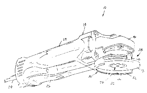
Fig. 1 is a perspective view of a power tool
equipped with a guard arrangement embodying the
invention.
Fig. 2 is an enlarged front elevational view of
the power tool illustrated in Fig. 1.
Fig. 3 is a front view of the power tool similar
to Fig. 2 but with the guard member and the tool
attachment removed from the power tool.
Fig. 4 is an enlarged side elevational view of the
front portion of the power tool illustrated in Fig. 1
and shown with the guard member in section and the tool
attachment removed.
Fig. 5 is a bottom plan view of the front portion
of the power tool illustrated in Fig. 4.
Fig. 6 is a view of the power tool similar to Fig.
5 but with the guard member also removed.
Fig. 7 is a view of the power tool similar to Fig.
5 but with the guard member shown in a mounting
position.
Fig. 8 is a perspective view of the guard member.
Before one embodiment of the invention is
explained in detail, it is to be understood that the
invention is not limited in its application to the
details of construction and the arrangements of
components set forth in the following description or
illustrated in the drawings. The invention is capable
of other embodiments and of being practiced or being
carried out in various ways. Also, it is to be
understood that the phraseology and terminology used
herein is for the purpose of description and should not
be regarded as limiting.

2 1 76~
--6--
DESCRIPTION OF A PREFERRED EMBODIMENT
Illustrated in Fig. 1 is a power tool 10. In the
particular embodiment illustrated in the drawings the
power tool 10 is an angle grinder on which is mounted a
removable work tool 12 such as an abrasive wheel.
The grinder 10 includes a housing 14 having a gear
case 16. The gear case 16 includes a hub portion 18
having (Figs. 3-7) an end face 20. The housing 14 also
includes a motor housing portion 22 mounted on the gear
case 16. A motor (not shown) is mounted in the motor
housing portion 22 and an electric power supply cord 24
extends from the back of the motor housing portion 22
to power the motor. A paddle switch 26 for controlling
power supply to the motor is mounted on the underside
of the motor housing portion 22.
The grinder 10 also includes (Figs. 1 and 2) a
spindle assembly 28 that forms part of a drive train
for driving the work tool 12 when the motor is
activated. The spindle assembly 28 is supported by the
gear case 16 and includes a spindle 30 that extends
outwardly from the end face 20 of the hub portion 18.
The spindle 30 has an axis of rotation 32 and a tool
receiving portion 34 on which the work tool 12 is
mountable. The spindle assembly 28 also includes a nut
36 that can be threaded onto the tool receiving portion
34 to secure the work tool 12 in place.
The grinder 10 also includes a guard arrangement
38 which embodies the invention. The guard arrangement
38 includes a removable guard member 40. As shown in
Fig. 8, the guard member 40 includes a protective guard
portion or hood member 4 2 that ( see Figs . 1 and 2 )
covers a portion of the work tool 12 when the guard
member 40 is mounted on the housing 14. The hood
member 42 is preferably a one-piece unit made of
metallic material and includes an annular plate-like
portion 44. For reasons more fully explained below,
the plate-like portion 44 is provided with a set of
radially-inwardly extending projections 46. In the

2 1 76428
illustrated arrangement that set includes (Figs. 5 and
7) four projections 46 that are unequally
circumferentially spaced apart.
The guard member 40 also includes an annual spacer
member or base 48 that is preferably made of a non-
metallic plastic material and that is secured in
coaxial relation to the plate-like portion 44 by
suitable means such as screws 50. The base 48 includes
(Fig. 8) a second set of four radially-inwardly
extending projections 52 that are spaced axially from
the projections 46. Projections 52 are
circumferentially spaced apart from each other to match
the spacing pattern and align with projections 46.
The guard arrangement 38 also includes means for
securing the guard member 40 on the housing 14 of the
grinder 10. In a preferred embodiment the guard member
40 is securable on the hub portion 18 and includes
means for installing or mounting the guard member 40 on
the hub portion 18. In the particular arrangement
illustrated in the drawings the mounting means includes
the two sets of projections 46 and 52 and corresponding
axially extending grooves 54 formed in the hub portion
18 and extending from the end face 20 thereof. The
grooves 54 are circumferentially spaced to match the
pattern of the projections 46 and 52 so that when the
projections are aligned with the grooves 54 (Fig. 7)
the guide member 40 can slide on and off the hub
portion 18. Since the projections 46 and 52 and the
grooves 54 are non-equidistantly circumferentially
spaced apart the guard member 40 must be positioned in
the predetermined angular position shown in Fig. 7
relative to the hub portion 18 in order for the guard
member 40 to be placed on the hub portion 18. As
explained below, the guard member 40 must also be
placed in that position relative to the hub portion 18
for the guard member 40 to be removed therefrom.

2 1 76428
The means for securing the guard member 40 on the
housing 14 also includes means for holding or
maintaining the guard member 40 on the housing 14 after
it is placed thereon. In the embodiment illustrated in
the drawings the holding means includes the projections
46 and 52 and (Figs. 3 and 4) a pair of annular grooves
56 and 58 formed in the hub portion 18. The annular
grooves 56 and 58 are spaced apart in an axial
direction the same distance as the projections 46 and
52. When the guard member 40 is slid fully onto the
hub portion 18, as shown in Fig. 4, the projections 46
and 52 register with the annular grooves 56 and 58,
respectively. The guard member 40 is then rotated or
shifted relative to the hub portion 18 to slide the
projections 46 and 52 into the annular grooves 56 and
58 so that the projections 46 and 52 become misaligned
(see Fig. 5) with respect to the axially extending
grooves 54. That misalignment secures the guard member
40 on the hub portion 18.
While the use of a single annular groove and
corresponding set of projections for holding the guard
member 40 in place on the grinder 10 can be used, a
pair of annular grooves 56 and 58 and two sets of
projections 46 and 52 provide greater stability for the
guard member 40 and are therefore preferred.
When the projections 46 and 52 are received in the
annular grooves 56 and 58 the guard member 40 is
rotatable relative to the hub portion 18 by 360
degrees. However, in the illustrated arrangement the
guard member 40 has a desired range of acceptable
angular positions. That range is defined by (Figs. 2,
3 and 6) a series of notches or detents 60 formed in
the hub portion 18 above the axially extending grooves
54. To secure or lock the guard member 40 in a
selected one of the angular positions defined by the
detents 60, the guard arrangement 38 is provided with
locking means which in the illustrated arrangement
includes a locking member or spring 62.

21 76428
As shown in Fig. 8, the locking spring 62 is
supported entirely on the guard member 40 so that when
the guard member 40 is removed from the housing 14 the
locking spring 62 is also removed therefrom. The
locking spring 62 includes (Fig. 4 and 8) a plate
section 64 that is fixed in position on the base 48.
The locking spring 62 also includes a locking portion
66 and a manually operable lever arm 68. The locking
portion 66 is engageable with the detents 60 to secure
the guard member 40 in a corresponding angular
position. To change the angular position of the guard
member 40 the lever arm 68 is finger-operable and can
be depressed to withdraw the locking portion 66 from a
detent 60 and thereby permit angular shifting of the
guard member 40.
In operation, the work tool 12 must be removed to
install the guard member 40. To mount the guard member
40 on the housing 14 the projections 46 and 52 are
aligned with the axially extending grooves 54 and the
guard member 40 is then slid onto the hub portion 18
until the projections 46 and 52 register with the
annular grooves 56 and 58, respectively. The guard
member 40 is then angularly shiftable to a desired
angular position, and once the projections 46 and 52
are misaligned with respect to the axially extending
grooves 54 the guard member 40 is held in place on the
hub portion 18. With the guard member 40 installed the
work tool 12 can be mounted on the tool receiving
portion 34 of the spindle 30 and secured thereon with
the nut 36.
The guard member 40 can be shifted with the tool
attachment 12 either removed or in place, and before
operating the grinder 10 the guard member 40 is shifted
to a desired angular position. During shifting it is
desireable to depress the lever arm 68 so that the
locking portion 66 does not interfere with rotational
movement of the guard member 40. When the guard member
40 is shifted to its desired angular position the lever

21 76428
--10--
arm 68 is released to permit the locking portion 66 to
engage the corresponding one of the detents 60 to
thereby lock the guard member 40 in that position. The
angular position of the guard member 40 can be changed
by simply depressing the lever arm 68, repositioning
the guard member 40, and then releasing the lever arm
68 to permit the locking portion 66 to engage the
appropriate detent 60.
To remove the guard member 40 the tool attachment
12 is removed and the guard member 40 is rotated from
its operative range to realign the projections 46 and
52 (Fig. 7) with the axially extending grooves 54. The
guard member 40 is then slid off of the hub portion 18.
While in the illustrated arrangement the power
tool is a grinder 10, it will be understood by one
skilled in the art that a guard arrangement embodying
the invention could be incorporated into a variety of
power tools including both portable hand-held tools and
other tools.
Advantageously, the guard arrangement 38 provides
convenient systems for installing the guard member 40,
adjusting the position of the guard member 40, and
securing the guard member in place. The guard
arrangement 38 combines those features in a compact
design which incorporates a position locking member
into the removable guard member 40 so that structure
associated with the guard arrangement 38 is
substantially unexposed if it is desirable to operate
the power tool without the guard member 40.
Various features of the invention are set forth in
the following claims.

Representative Drawing
A single figure which represents the drawing illustrating the invention.
Administrative Status

2024-08-01:As part of the Next Generation Patents (NGP) transition, the Canadian Patents Database (CPD) now contains a more detailed Event History, which replicates the Event Log of our new back-office solution.

Please note that "Inactive:" events refers to events no longer in use in our new back-office solution.

For a clearer understanding of the status of the application/patent presented on this page, the site Disclaimer , as well as the definitions for Patent , Event History , Maintenance Fee  and Payment History  should be consulted.

Event History

Description Date
Inactive: IPC from MCD 2006-03-12
Application Not Reinstated by Deadline 2004-03-19
Inactive: Dead - No reply to s.30(2) Rules requisition 2004-03-19
Inactive: Abandoned - No reply to s.30(2) Rules requisition 2003-03-19
Inactive: S.30(2) Rules - Examiner requisition 2002-09-19
Letter Sent 1999-07-05
Inactive: Status info is complete as of Log entry date 1999-07-05
Inactive: Application prosecuted on TS as of Log entry date 1999-07-05
Request for Examination Requirements Determined Compliant 1999-06-11
All Requirements for Examination Determined Compliant 1999-06-11
Application Published (Open to Public Inspection) 1996-12-29

Abandonment History

There is no abandonment history.

Maintenance Fee

The last payment was received on 2003-04-22

Note : If the full payment has not been received on or before the date indicated, a further fee may be required which may be one of the following

  • the reinstatement fee;
  • the late payment fee; or
  • additional fee to reverse deemed expiry.

Patent fees are adjusted on the 1st of January every year. The amounts above are the current amounts if received by December 31 of the current year.
Please refer to the CIPO Patent Fees web page to see all current fee amounts.

Fee History

Fee Type Anniversary Year Due Date Paid Date
MF (application, 2nd anniv.) - standard 02 1998-05-13 1998-04-09
MF (application, 3rd anniv.) - standard 03 1999-05-13 1999-03-18
Request for examination - standard 1999-06-11
MF (application, 4th anniv.) - standard 04 2000-05-15 2000-04-18
MF (application, 5th anniv.) - standard 05 2001-05-14 2001-03-26
MF (application, 6th anniv.) - standard 06 2002-05-13 2002-03-28
MF (application, 7th anniv.) - standard 07 2003-05-13 2003-04-22
Owners on Record

Note: Records showing the ownership history in alphabetical order.

Current Owners on Record
MILWAUKEE ELECTRIC TOOL CORPORATION
Past Owners on Record
CHUNGKIN YEE
Past Owners that do not appear in the "Owners on Record" listing will appear in other documentation within the application.
Documents

To view selected files, please enter reCAPTCHA code :


To view images, click a link in the Document Description column (Temporarily unavailable). To download the documents, select one or more checkboxes in the first column and then click the "Download Selected in PDF format (Zip Archive)" or the "Download Selected as Single PDF" button.

List of published and non-published patent-specific documents on the CPD .

If you have any difficulty accessing content, you can call the Client Service Centre at 1-866-997-1936 or send them an e-mail at CIPO Client Service Centre.

({010=All Documents, 020=As Filed, 030=As Open to Public Inspection, 040=At Issuance, 050=Examination, 060=Incoming Correspondence, 070=Miscellaneous, 080=Outgoing Correspondence, 090=Payment})


Document
Description 
Date
(yyyy-mm-dd) 
Number of pages   Size of Image (KB) 
Representative drawing 1998-03-31 1 14
Representative drawing 2002-09-04 1 13
Abstract 1996-08-20 1 24
Description 1996-08-20 10 446
Claims 1996-08-20 7 253
Drawings 1996-08-20 6 100
Reminder of maintenance fee due 1998-01-20 1 111
Acknowledgement of Request for Examination 1999-07-04 1 179
Courtesy - Abandonment Letter (R30(2)) 2003-05-27 1 167