Language selection

Search

Patent 2176938 Summary

Third-party information liability

Some of the information on this Web page has been provided by external sources. The Government of Canada is not responsible for the accuracy, reliability or currency of the information supplied by external sources. Users wishing to rely upon this information should consult directly with the source of the information. Content provided by external sources is not subject to official languages, privacy and accessibility requirements.

Claims and Abstract availability

Any discrepancies in the text and image of the Claims and Abstract are due to differing posting times. Text of the Claims and Abstract are posted:

  • At the time the application is open to public inspection;
  • At the time of issue of the patent (grant).
(12) Patent: (11) CA 2176938
(54) English Title: DEVICE FOR ADMIXING A PROCESSING AGENT TO A PULP SUSPENSION
(54) French Title: DISPOSITIF SERVANT A AJOUTER UN AGENT DE TRAITEMENT A UNE SUSPENSION DE PATE
Status: Expired and beyond the Period of Reversal
Bibliographic Data
(51) International Patent Classification (IPC):
  • D21B 01/34 (2006.01)
  • D21D 05/28 (2006.01)
(72) Inventors :
  • FORSLUND, KJELL (Sweden)
(73) Owners :
  • VALMET FIBERTECH AKTIEBOLAG
  • SUNDS DEFIBRATOR INDUSTRIES AB
(71) Applicants :
  • VALMET FIBERTECH AKTIEBOLAG (Sweden)
  • SUNDS DEFIBRATOR INDUSTRIES AB (Sweden)
(74) Agent: SMART & BIGGAR LP
(74) Associate agent:
(45) Issued: 2004-07-20
(86) PCT Filing Date: 1994-10-27
(87) Open to Public Inspection: 1995-06-29
Examination requested: 2001-08-14
Availability of licence: N/A
Dedicated to the Public: N/A
(25) Language of filing: English

Patent Cooperation Treaty (PCT): Yes
(86) PCT Filing Number: PCT/SE1994/001009
(87) International Publication Number: SE1994001009
(85) National Entry: 1996-05-17

(30) Application Priority Data:
Application No. Country/Territory Date
9304240-6 (Sweden) 1993-12-21

Abstracts

English Abstract


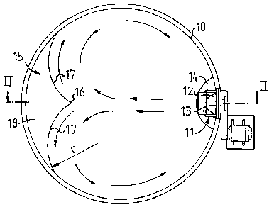
A device for admixing a processing agent to a pulp suspension. The device comprises a cylindric lower portion (10) of a vessel with
an agitator (11) fitted into the wall of said vessel portion, which agitator is intended to bring about a pulp flow across the vessel portion (10).
Means are provided (13) for the supply of the processing agent to the pulp flow. A flow divider (15) is located in the vessel portion (10)
diametrically opposite the agitator (11). Said flow divider (15) comprises a substantially vertical front distribution edge (16) and are-shaped
surfaces (17) extending from the distribution edge (16) one in each direction, which surfaces are substantially vertical and join the wall of
the vessel portion (10).


French Abstract

Un dispositif servant à ajouter un agent de traitement à une suspension de pâte comprend une partie inférieure cylindrique (10) d'un réservoir équipé d'un agitateur (11) fixé dans la paroi dudit réservoir. L'agitateur a pour fonction de faire circuler un flux de pâte à travers la partie (10) du réservoir. Une installation (13) est prévue pour assurer l'alimentation du flux de pâte en agent de traitement. Un diviseur de débit (15) est logé de façon diamétralement opposée à l'agitateur, dans la partie (10) du réservoir. Le diviseur de débit (15) comprend une arête de distribution frontale quasiment verticale (16) ainsi que des surfaces cintrées (17) s'étendant chacune dans une direction, à partir de l'arête de distribution (16). Les surfaces cintrées sont pratiquement verticales et reliées à la paroi de la partie (10) du réservoir.

Claims

Note: Claims are shown in the official language in which they were submitted.


4
CLAIMS:
1. A mixing device for mixing a processing agent with
a suspension comprising a mixing vessel having an inner
surface and including a lower cylindrical portion having a
diameter, an agitator mounted with respect to said inner
surface of said mixing vessel for creating a flow of said
suspension across said mixing vessel, processing agent
supply means for supplying said processing agent to said
flow of said suspension across said mixing vessel, and a
flow divider mounted with respect to said inner surface of
said mixing vessel at a location substantially opposite to
the location of said agitator, said flow divider comprising
a substantially vertical front distribution edge spaced from
said inner surface of said mixing vessel and a pair of
arcuate front surfaces extending from said front
distribution edge to said inner surface of said mixing
vessel on opposite sides of said front distribution edge,
said pair of arcuate front surfaces including an upper
surface defining an inclined plane with respect to said
inner surface of said mixing vessel.
2. The mixing device of claim 1 wherein said pair of
arcuate front surfaces are substantially vertical.
3. The mixing device of claim 1 wherein said
suspension comprises a pulp suspension.
4. The mixing device of claim 1 wherein said pair of
arcuate front surfaces extend to said inner surface of said
mixing vessel substantially tangentially.
5. The mixing device of claim 1 wherein said front
distribution edge is directly opposite said agitator.

5
6. The mixing device of claim 1 wherein said front
distribution edge is located on a diameter of said mixing
vessel, and said pair of arcuate front surfaces comprise
cylindrical surfaces having a predetermined radius.
7. The mixing device of claim 6 wherein said
predetermined radius is between about 20 and 25% of said
diameter of said mixing vessel.
8. The mixing device of claim 1 wherein said front
distribution edge has a height, said height being between
about 10 and 20% of said diameter of said mixing vessel.
9. The mixing device of claim 8 wherein said upper
surface of said pair of arcuate front surfaces has a maximum
height, said maximum height being between about 40 and 60%
of said diameter of said mixing vessel.
10. The mixing device of claim 1 wherein said inner
surface of said mixing vessel includes a bottom surface,
said bottom surface being substantially horizontal whereby
said agitator creates a flow of said suspension across said
mixing vessel to said flow divider which is substantially
unobstructed therebetween.

Description

Note: Descriptions are shown in the official language in which they were submitted.


CA 02176938 2004-03-09
28229-70
1
Device for admixing a processing agent to a pulp suspension
This invention relates to a device for admixing a processing agent
to a pulp suspension in a vessel. The processing agent can consist
of liquids and chemicals, substantially in fluid state, for dilution
or other types of processing.
A persistently uniform and proportional admixture of the processing
agent to the pulp is of decisive importance for achieving an accept-
able result at all types of pulp processing.
In known arrangements the processing agent is admixed in the lower
portion of a pulp vessel. The pulp concentration in the pulp vessel
normally is 10-20%, which must be lowered to about 2,5-8% for mak-
ing it possible to pump the pulp suspension out from the vessel. When
the pulp vessel is used as bleaching tower, it is necessary to supply
dilution through a number of nozzles in a restricted lower portion
of the tower. The bottom zone of the tower there is restricted by
a cylindric cone for guiding the processing agent in a circular way.
A high pulp concentration, for example 12%, in the vessel randers
it problematic to achieve a uniform admixture. In order to reduce
the problem, the size of the vessel has been reduced. Such an arr-
angement even requires much energy, due to an incomplete admixture
technique and to an unsuitable configuration of the bottom.
According to the present invention, the aforesaid problems are
eliminated, in that the processing agent is supplied and distributed
centrally and the flow is improved. An improved mixing result is
achieved, and at the same time the energy consumption is lowered
to a minimum. The characterizing features of the invention are
apparent from the attached claims.

CA 02176938 2004-03-09
28229-70
la
Thus, in a broad aspect, the invention provides a
mixing device for mixing a processing agent with a
suspension comprising a mixing vessel having an inner
surface and including a lower cylindrical portion having a
diameter, an agitator mounted with respect to said inner
surface of said mixing vessel for creating a flow of said
suspension across said mixing vessel, processing agent
supply means for supplying said processing agent to said
flow of said suspension across said mixing vessel, and a
flow divider mounted with respect to said inner surface of
said mixing vessel at a location substantially opposite to
the location of said agitator, said flow divider comprising
a substantially vertical front distribution edge spaced from
said inner surface of said mixing vessel and a pair of
arcuate front surfaces extending from said front
distribution edge to said inner surface of said mixing
vessel on opposite sides of said front distribution edge,
said pair of arcuate front surfaces including an upper
surface defining an inclined plane with respect to said
inner surface of said mixing vessel.
The invention is described in greater detail in
the following, with reference to the accompanying Figures
illustrating an embodiment of the invention.

WO 95/I7243 217 6 9 3 8 PCTBE94101009
2
Fig. 1 shows the lower portion of the processing vessel,
Fig. 2 is a section according to II-II in Fig. 1,
Figs. 3 and 4 show in a schematic manner different alternatives
of the embodiment according to Figs. 1 and 2.
Y
The mixing vessel according to Fig.1 comprises a cylindric lower
portion 10. An agitator 11 is fitted into the wall of the lower
portion of the vessel. The agitator 11 comprises a propeller 12,
which is intended to bring about a pulp flow across the vessel
portion 10 simultaneously as a processing agent is supplied to the
pulp flow. According to the embodiment shown, the processing agent
is supplied through a pipe 13 located above the suction side of the
agitator 11, and an inclined screen 14 is located in the vessel
above the pipe 13. Said screen 14 is intended to distribute the in-
going processing agent on the suction side of the agitator 11 and
at the same time to prevent air to be sucked in from the surface
of the pulp suspension in the vessel. There is risk of air being
sucked in when the level in the vessel approaches the level of
the agitator.
As an alternative, the propeller agitator can be designed in a
different way, for example as shown in patent application SE
No 9202011-4.
Diametrically opposite the agitator- 11, the lower portion 10 of
the vessel is formed with a flow divider 15. A substantially vertic-
al distribution edge 16 on the front of this flow divider 15
is located on the central line of the agitator 11 at a distance
from the wall of the vessel portion 10. Two arc-shaped substant-
ially vertical surfaces 17 extend, one in each direction, from
the distribution edge 16 outward to the-vessel wall which these
surfaces 17 joih substantially tangentially. The surfaces 17 are
symmetrical as regards the distribution edge 16 and are defined
upwardly by an inclined plane 18 forming an angle v with the
vessel wall.

WO 95117243 . 2 l 7 6 9 3 8 p~.~E94/01009
3
The arc-shaped surfaces 17 preferably are cylindric with a radius
_r which is 20-25~ of the diameter D ~ the vessel portion 10. The
~ center axis of each of the arc-shaped surfaces 17 and the distrib-
ution edge 16 should be located in the opposed half of the vessel
portion 10 in relation to the agitator 11, but the distance between
said center axis and, respectively, distribution edge and the
imaginary plane dividing the vessel portion 10 into two halves
should be smaller than 20~ of the diameter D.
The height _h of the distribution edge 16 should be 10-20~ of the
diameter D, counted from the vessel bottom. The highest point
where the inclined plane 18 joins the wail of the vessel portion
should be located at a height H above the vessel bottore, where
H lies in the interval 40-60~ of the diameter D. The angle _v
determined by the difference between the heights h and H should
be about 45°.
Due to the design of the lower portion 10 of the vessel provided
with a flow divider 15, the throw length of the agitator 11 is
shortened and at the same time the pulp flow is divided into two
partial flows of equal size. These partial flows flow back along
the vessel wall and further to the suction side of the agitator
11 where simultaneously the inclined plane 18 produces a certain
upward deflection. The pulp flow guided in this manner yields.a
very effective mixing and requires less energy supply than mixing
arrangements heretofore used. __
The invention, of course, is not restricted to the embodiments
shown, but can be varied within the scope of the invention idea.

Representative Drawing
A single figure which represents the drawing illustrating the invention.
Administrative Status

2024-08-01:As part of the Next Generation Patents (NGP) transition, the Canadian Patents Database (CPD) now contains a more detailed Event History, which replicates the Event Log of our new back-office solution.

Please note that "Inactive:" events refers to events no longer in use in our new back-office solution.

For a clearer understanding of the status of the application/patent presented on this page, the site Disclaimer , as well as the definitions for Patent , Event History , Maintenance Fee  and Payment History  should be consulted.

Event History

Description Date
Inactive: IPC expired 2022-01-01
Time Limit for Reversal Expired 2010-10-27
Letter Sent 2009-10-27
Inactive: IPC from MCD 2006-03-12
Grant by Issuance 2004-07-20
Inactive: Cover page published 2004-07-19
Pre-grant 2004-04-29
Inactive: Final fee received 2004-04-29
Letter Sent 2004-04-14
Notice of Allowance is Issued 2004-04-14
Inactive: Approved for allowance (AFA) 2004-04-05
Amendment Received - Voluntary Amendment 2004-03-09
Inactive: S.30(2) Rules - Examiner requisition 2003-10-06
Inactive: Application prosecuted on TS as of Log entry date 2001-09-12
Letter Sent 2001-09-12
Inactive: Status info is complete as of Log entry date 2001-09-12
Request for Examination Requirements Determined Compliant 2001-08-14
All Requirements for Examination Determined Compliant 2001-08-14
Inactive: Multiple transfers 2000-08-21
Application Published (Open to Public Inspection) 1995-06-29

Abandonment History

There is no abandonment history.

Maintenance Fee

The last payment was received on 2003-10-02

Note : If the full payment has not been received on or before the date indicated, a further fee may be required which may be one of the following

  • the reinstatement fee;
  • the late payment fee; or
  • additional fee to reverse deemed expiry.

Patent fees are adjusted on the 1st of January every year. The amounts above are the current amounts if received by December 31 of the current year.
Please refer to the CIPO Patent Fees web page to see all current fee amounts.

Owners on Record

Note: Records showing the ownership history in alphabetical order.

Current Owners on Record
VALMET FIBERTECH AKTIEBOLAG
SUNDS DEFIBRATOR INDUSTRIES AB
Past Owners on Record
KJELL FORSLUND
Past Owners that do not appear in the "Owners on Record" listing will appear in other documentation within the application.
Documents

To view selected files, please enter reCAPTCHA code :


To view images, click a link in the Document Description column. To download the documents, select one or more checkboxes in the first column and then click the "Download Selected in PDF format (Zip Archive)" or the "Download Selected as Single PDF" button.

List of published and non-published patent-specific documents on the CPD .

If you have any difficulty accessing content, you can call the Client Service Centre at 1-866-997-1936 or send them an e-mail at CIPO Client Service Centre.


Document
Description 
Date
(yyyy-mm-dd) 
Number of pages   Size of Image (KB) 
Representative drawing 1997-06-25 1 6
Abstract 1995-06-28 1 44
Description 1995-06-28 3 111
Claims 1995-06-28 2 44
Drawings 1995-06-28 2 24
Claims 2004-03-08 2 69
Description 2004-03-08 4 142
Representative drawing 2004-04-05 1 8
Abstract 2004-05-13 1 44
Description 2004-07-18 4 142
Drawings 2004-07-18 2 24
Abstract 2004-07-18 1 44
Reminder - Request for Examination 2001-06-27 1 118
Acknowledgement of Request for Examination 2001-09-11 1 194
Commissioner's Notice - Application Found Allowable 2004-04-13 1 161
Maintenance Fee Notice 2009-12-07 1 170
Correspondence 2000-09-18 1 19
PCT 1996-05-16 6 305
Correspondence 2004-04-28 1 31
Fees 1996-05-16 1 44