Note: Descriptions are shown in the official language in which they were submitted.
21~058
`-- 1 P-PWU-300/EX
DEVICE FOR CHARGING AN ELECTRIC FURNACE
The invention relates to a device for charging an electric furnace with a
molten metal.
5A large part of the recycling of scrap iron is achieved using electric furnacessuch as arc furnaces. These furnaces make it possible to melt and reuse the scrap
iron treated in this way in order to make new steel products such as girders, etc.
Some of the residual elements contained in the scrap iron, such as copper,
nickel, etc., cannot be separated from the steel and are therefore present in the
10 finished products. The more the scrap iron has been subjected to recycling
operations, the higher will be the concentration of these residual elements. Thelatter are a nuisance in the manufacture of certain products such as steel sheets,
etc.
One way of reducing the concentration of residual elements in the steel
obtained from scrap iron is to add some liquid iron directly to the electric furnace.
This method necessitates the removal of the cover of the electric furnace. It istherefore necessary to interrupt the process of melting the scrap iron, to move the
cover and to pour the liquid iron into the electric furnace over the partially melted
scrap iron. During this operation, large quantities of dust are released into the
20 atmosphere and part of the iron or the partially melted steel is ejected from the
furnace. Furthermore, the impact of the liquid iron risks damaging the cooling
panels lining the inside of the furnace. It is clear that this method is insalubrious,
dangerous and reduces the productivity of the furnace.
The aim of the present invention is to put forward a device avoiding to
25 damage the furnace by projections of cast iron during the introduction of liquid cast
iron and to minimize the loss of heat.
According to the present invention, this aim is achieved by a charging
device intended to supply liquid metal to an electric furnace with a hearth, said
device comprising a balcony extending the furnace hearth laterally, said balcony30 being covered internally with a coating of a refractory material.
2177û~8
-- 2 P-PWU-300/EX
The device is characterised by a cover, equipped with a refractory coating,
located above said balcony, said cover forming in an open position a protection
shield for a part of the furnace (10) adjacent to the said device.
In the charging device according to the invention, the iron is no longer
5 poured directly into the shaft of the electric furnace (e.g. from a ladle), but is
introduced by a projecting lateral balcony communicating with the hearth of the
electric furnace. There is consequently no longer any need to remove the furnacecover and interrupt the process of melting the scrap iron during the introduction of
the molten metal. The productivity of the furnace is increased since the charging
10 with iron is carried out while the plant is running. The working life of the cooling
panels in the furnace shaft is increased since the iron is no longer thrown against
these panels during the charging.
Moreover, emissions of dust into the atmosphere are limited since the liquid
iron comes into contact with the scrap iron below the cover of the electric furnace.
15 Consequently, the dust that is created is sucked away and dealt with by the
furnace filtration system.
In addition, the refining of the molten metal may be initiated by the injection
of oxygen from the beginning of the production cycle.
The inner surface of the said balcony is entirely covered by a refractory
20 material in order to protect the balcony against the heat from the liquid iron.
Preferably, the bottom of the balcony is faced with an impact plate made of a
special refractory in order to prevent its premature wear.
It will also be appreciated that the supply balcony incorporates a cover
fitted with a lining made of a refractory material which minimises heat losses and
25 which forms a protective shield for a part of the furnace adjacent to the said device
when it is open. In this way, the furnace is protected against ejections of liquid iron
during the charging.
Preferably, the lateral supply balcony will be positioned near the tap hole.
This arrangement has the advantage that the door of the furnace can remain
30 closed during the addition of the liquid iron. Standard operations carried out
through the door are not hampered.
21771~58
3 P- PWU- 300/EX
In order to prevent the liquid iron from running directly from the lateral
balcony into the tap hole and thus complicating the operation of pouring in the
ladle, a flow channel may be made in the refractory from the hearth of the lateral
balcony to the centre of the furnace.
If necessary, a raised section or a dam may be positioned between the flow
channel and the tap hole so as to deflect the iron from the tap hole.
The positioning near the tap hole of the balcony used for charging the
furnace with iron and the possibility of pouring a precise amount of iron also allow
part of the liquid metal contained in the ladle to be poured directly into the steel-
casting ladle intended to receive molten steel coming from the furnace with the
aim of slightly altering this steel. In this way, energy is saved and the alloying
elements (C, Mo, Si) are recovered.
According to an advantageous embodiment, a barrier is located between
the balcony and the shaft of the electric furnace which has the effect of creating, in
the lower part of the balcony, a bottom filled with molten metal during the whole of
the time when the iron is being poured into the lateral balcony. In this way, the
ejections of liquid iron during the pouring are limited.
The barrier is preferably detachable. It may then be easily replaced when it
is worn.
Advantageously, the barrier has one or more openings made in the base of
the said barrier in order to allow the said balcony to be emptied after the furnace
has been charged with the iron.
Additional advantages and characteristics will emerge from the detailed
description of advantageous embodiments of the invention given below, solely as
illustrative examples, with reference to the appended drawings, in which:
- Figure 1 is a longitudinal cross-section through an electric furnace
incorporating a charging device for liquid iron.
- Figure 2 shows a plan view of an electric furnace.
- Figure 3 represents a cross-section along the line 111-111 of Figure 2.
- Figure4 represents a longitudinal cross-section through an electric
furnace incorporating a charging device for liquid iron equipped with a barrier.
2 17~58
-- 4 P-PWU-300/EX
- Figure 5 represents a cross-section through the furnace of Figure 4 at the
level of the tap hole.
- Figure 6 represents a cross-section along the line lll-lll of Figure 5.
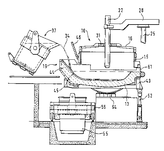
Figure 1 shows an electric furnace 10 comprising a hearth 13 made of a
s refractory material surmounted by a shaft 15 and a cover 16 together with a lateral
balcony 19 or charging spout for supplying liquid iron to the furnace 10.
In order to charge the furnace with scrap iron, the cover 16 is removed and
the scrap iron is then poured into the furnace shaft. When the shaft 15 is filled with
scrap iron, the cover 16 is replaced on the shaft 15 and at least one electrode 22
mounted on a supporting post 25 by means of an arm 28, is introduced into the
furnace 10 through an opening 31 made in the cover 16. The arm 28 may slide on
the supporting post 25 so that it can ascend and descend with the electrode 22.
A hot-metal ladle 37 is positioned near the lateral balcony 19 by means of a
crane or a tilting carriage (not shown). The ladle 37 is inclined and the liquid iron
34 is poured into the lateral balcony 19.
The lateral balcony 19 is fitted with a lining composed of a refractory
material 44 and its bottom is faced with an impact plate 45 made of a special
refractory so as to protect the balcony 19 against wear.
A cover 46 limits the heat loss from the furnace through the balcony 19. The
cover 46, when open during the loading of the liquid iron into the furnace, protects
the furnace against ejections of the liquid iron 34.
The furnace 10 is mounted on a cradle 49 enabling it to be tilted by means
of a hydraulic actuator 52. When the actuator 52 is retracted, the cradle 49 andthe furnace 10 tilt on their tilting seat 54 located below the cradle 49. The furnace
10 iS balanced so that it returns to a horizontal position even if the hydraulic circuit
supplying the actuator 52 breaks down.
When the scrap iron has melted, the liquid steel is poured into a steel-
casting ladle 55 through a tap hole 58. This ladle 55 is mounted on a carriage 56
running on rails and is brought below the tap hole 58.
The slag is removed through a lateral slag-removal door 61 by tilting the
furnace 10 on its seating 54.
2l77n~s
5 P - PWU- 300/EX
Figure 2 shows a plan view of the furnace 10. The position of the lateral
balcony 19 in relation to the tap hole 58 can be seen in this figure. The balcony is
displaced laterally with respect to the tap hole 58 so as to prevent the liquid iron
from being poured directly into the tap hole, but so as to make it flow towards the
s centre of the furnace 10 instead.
Figure 3, a cross-section along the line lll-lll' of Figure 2, shows a dam 65
demarcating a flow channel 68 for the liquid iron.
Figure 4 represents a preferred embodiment in which the lateral balcony 19
is demarcated from the shaft of the furnace 10 by a barrier 40 which temporarilyretains the iron 34. The balcony 19 is filled up to the height of the barrier 40 and
the iron 34 is then thrown over the barrier 40 into the hearth 13. At the base of the
barrier 40, one or more openings 43 are made which allow the balcony 19 to be
emptied at the end of the charging with the iron 34. In order to maintain a pig bed
in the balcony 19, it is sufficient to adjust the flow rate of the iron 34 supplied to
the balcony 19 so that it is greater than the flow rate of the iron passing through
the openings 43 made in the base of the barrier 40.
It can be seen in Figure 5 that the barrier 40 is located in vertical slides 71,allowing it to be easily replaced when it is worn. The barrier 40 has two handles 76
by which it may be removed from the slides.
Figure 6, a cross-section along the line lll-lll' of Figure 5, shows a dam 65
demarcating a flow channel 68 for the liquid iron. The barrier 40 is located in
vertical slides 71, allowing it to be easily replaced when it is worn. The barrier 40
has two handles 76 by which it may be removed from the slides 71.